
Abstract
Complex composite structure design is frequently practiced in today’s aerospace and automotive industries. This study deals with the winding optimization of polymer composite frames having complex 3D geometry using rovings, winding heads, and industrial robots. This problem is addressed mainly from a geometrical perspective using a novel mathematical model and approach. Attention is given to maintaining the required winding angles, avoiding gaps, minimizing roving overlaps during winding, and ensuring the homogeneity of the windings process. Determination of the optimal number of rovings used and their width during the winding process is solved first for the case of a straight frame, where the central axis of the wound roving forms a straight helix on the frame surface. The winding technology for curved parts of the frame is more complicated. In practice, the curved section of the frame often forms geometrically part of a ring torus. The central axis of the wound roving then forms a toroidal helix on the torus. Optimization procedures are also solved for this type of frame. The verification of the derived theoretical conclusions was done using practical examples is a part of the research.
Keywords
Introduction
Today, composite materials are increasingly used in developing and fabricating many products. They gradually replace conventional materials such as wood, steel, iron, and metal alloys.1,2 Its advantages include lightness, aggressive environment resistance, maintenance-free, tensile, flexural, and compressive strength.2,3 Recently, polymer composite frame applications have expanded. They are mainly used as reinforcements for aircraft wings and fuselages, landing gears, cabins, and doors of cars. Composite frames are also used to construct safety cab frames for off-road vehicles and agricultural machinery (e.g. tractors and harvesters), boats (hull reinforcements, masts), and sporting goods, especially bicycles.1,4–6 Figure 1 shows examples of composite frames. They can be open (a) or closed (b), (c) and are often spatially constructed.

Frame shapes: (a) open composite frame of complicated shape, (b) closed frame with test winding of one roving, and (c) closed composite frame.
Figure 2 describes each step of the composite frame development process, while the individual steps are explained below in more detail.

Schematic diagram of the composite frame development process.
Steps 1 and 2
Before starting the development of a composite frame, it is necessary to determine the shape and dimensions of the frame. Composite frames are often shaped only in 2D space. Determining the correct winding procedure is usually easier in such cases. In general, curved parts of frames shaped in 2D and 3D are the most difficult to wind. It is also necessary to define the requirements for the physical and mechanical properties of the future composite to ensure the composite frame’s tensile, flexural, torsional, and compressive strength. Aggressive environment resistance with minimal maintenance is often essential to the composite requirements. A critical environmental aspect is the need for longer lifespans for composite frames and their recycling.
Step 3
The material composition and production technology are designed based on the specified requirements for the composite frame. The material composition includes:
the type and properties of reinforcement (e.g. carbon, glass, basalt, aramid roving) and polymer matrix (thermosets, thermoplastic),
number and orientation of layers,
reinforcement preparation technology.
Three-dimensional or closed shapes require using a lightweight core, which has no significant effect on the final weight of the composite and its mechanical properties. Software modeling tools (e.g. Ansys, Abaqus) significantly assist in determining the components of composite and its mechanical properties.
Step 4
This step focuses on the issue of proper fiber winding on a composite frame from a geometric perspective and is the main focus of the article.
Step 5
The frame dry rovings reinforcement is then impregnated with resin and cured. Resin Transfer Molding (RTM) or vacuum infusion technologies are often used, depending on the resin type. The core (often from polyurethane foam) remains part of the finished composite.
Step 6
Followed by a comparison of the determined properties of the composite structure model (step 3) and the physical/measured values obtained by loading the composite component.
Steps 7 and 8
If the results of the practical tests of the composite prototype are in agreement, the technology for manufacturing the composite frame, including material composite composition, can be accepted. Otherwise, changes in previous Steps need to be made in the proposal, for example, in Step 3 when modeling the composite or material composition/composite structure in Step 2.
Roving is a fiber unit consisting of continual, unidirectional oriented filaments, usually without twists. Its cross-section has a lenticular shape.
The current research on mechanics of composite materials and structures mainly engaged on the issue of mechanical design at material and structural aspects, material characterizations, 7 determination of mechanical behavior of composite structures at elastic to damage, and failure stages while considering structural response of composite subjected to various loads, 8 invention of high-performance materials with improve functionality for smart application and technology, 9 engineering of materials for improving structural features within mechanical, thermal or even electrical features, 10 etc. Within the mechanical-manufacturing aspects, the development of bio-based and biodegradable composites (lessen the environmental effect by traditional synthetic materials),11,12 structure with tailored properties at micro-to-meso level13,14, 3D/4D printing within additive manufacturing techniques,15,16 etc. Experimental mechanics, assisted computational and numerical techniques have been the most wrought methods accompanied to provide comprehensive insight for multidisciplinary study of composite and push the boundaries to create innovation and design based on complex industrial challenges.17–19 Although a lot of researches accomplished in these aspects, however there are plenty of aspects missing in the loop of manufacturing of complex composite structures including; defect formation at different material-levels for higher integration through compacting and layups, 20 guaranteeing uniform resin flow, and wetting to dense fibers, 21 stable curing process and thermal control for of optimum structural solidification,22,23 scalability of the structure considering the fabrication techniques, as well as incorporation of automation and robotics and quality control in the manufacturing processes.24,25 Emphasis in quality production of complex composite structures for aerospace applications was a the main basis in emerge of robotics and automation involvement in manufacturing of high-quality and high-performance structure pursued in research and development sectors of todays advanced industries.26,27 In this regard, robot winding is proven to be an effective method for quality production of curved composite frame, and recent researches has focused on optimization of winding processes. However, the problem of winding quality (winding angles, gaps reduction, or roving overlaps) is given much less attention in current research states. To solve this issue, the correct geometrical winding is essential to ensure the desired properties of the composite frame. For example, compliance with the prescribed angles of fiber layer orientation onto the frame is necessary to provide the composite’s resistance to mechanical stresses.28–35
The most common manufacturing processes for composite frames are braiding technology and filament winding. Two oppositely oriented layers from longitudinal textiles interlaced to crossing points characterize the braiding technology. The braided structure’s benefit is the high adhesion of the fiber layer to the surface of the core or frame and the exact copy of the shape. Changes in cross-sectional shape or size are usually easy to solve by changing the feed rate. The core-feeding rate and trajectory shape are realized by using a robot.36–38
In a commonly used procedure for filament winding technology, the frame core is rotated around its central axis. At the same time, the fibers are fed by a device attached to the robotic arm and moving parallel to the axis of the core. The angle of the filament winding depends on the speed of rotation of the frame core around the axis and the speed of movement of the filament feeder. The fibers are impregnated with resin before winding. Filament winding techniques are discussed, for example, in article, 39 and the advantages and disadvantages of using the winding technology are discussed in article. 40 Publication 41 examines the conditions for maintaining the required winding angle.
The braiding technology and fiber winding procedures mentioned above are not applicable to the closed frame shape. The basis of the equipment for the production of braided structures is a ring with two rail lines for the opposing movement of the fiber carriers. Interference with the ring in terms of opening and closing it would be very complicated. For this reason, braiding machine manufacturers do not even offer a closed-core version of the braiding machine.
This paper focuses on a different winding technology of filament fibers on open- and closed-frame core types. Winding technology applies under certain conditions to frames with different cross-sectional shapes, such as circles, ellipses, triangles, or rectangles. The problem of winding rovings on a non-load-bearing frame of circular cross-section is solved in this article.
The winding head and industrial robot are used in the winding process. The frame is attached to the end of the robot’s working arm (robot-end-effector), and, based on the suitable trajectory of the robot-end-effector, the frame gradually passes through the rotating rings of the winding head at a defined speed – a unidirectional fiber layers formed on the frame from coils located on the circumference of the rotating rings of the winding head (Figures 3(a), (b) and 4(a)). The setting of the size of the winding angle between the fiber layer and the frame axis is based on the assumption that the speed of the frame passage is constant and, at the same time, the variable angular velocity of the rotating ring (the robot’s external axis controls the angular velocity of the rotating ring). The winding of two fiber rovings onto the frame as the frame passes through the winding head with two rotating rings is shown in Figure 3(b). A detail of the winding head is shown in Figure 3(c).

(a) Preparation of winding 2 layers of rovings on the frame attached to the robot-end-effector. (b) An example of winding only two carbon rovings on the frame is one at +45° and the other at −45° by two rotated ring of winding head. (c) Winding head with three rotating rings and spools.

(a) Three rotating rings of winding head with glass rovings, (b) winding a straight frame with carbon rovings, and (c) combined winding with carbon and glass rovings.
The rotating rings of the winding head are openable to allow winding of the closed frame core. Fiber rovings are wound dry only, wet winding cannot be used. The fibers are impregnated with resin after the winding process. To ensure the requested winding angle, it is also important, the central axis of the frame must be perpendicular to the plane of the rotating ring as the frame passes through the winding head. The rotate rings of winding head are composed of coils with fiber rovings (Figures 3(c), 4(a) and (b)). When passing the frame through a winding head with three winding rotating rings, the perpendicular position is approximated so that the individual winding angles are as close as possible to the desired value (deviation between the frame axis and the plane of the winding ring to be as close to 90° as possible). The problem of determining the optimized robot trajectory and ensuring the correct angle of roving winding for individual layers is described and solved in detail in the literature.1,42 Figure 4(b) shows the winding of the straight frame by carbon rovings and 4(c) combined winding with carbon and glass rovings.
The winding of a frame with two parts with different radii of cross-section is conditioned by a continuous transition between the parts (a truncated cone). The winding angle of fibers depends on the speed of passage of the frame through the winding head, the angular speed of rotation of the winding head ring and the frame radius. The speed of frame through the winding head is constant. To maintain the same winding angle on both parts of the frame, it is necessary to continuously change the angular speed of the rotating ring of the winding head (angular speed is controlled by the external axis of the robot). This issue is dealt with in detail in article. 4
Material and methods
Achieving the required winding angle and roving windings without gaps and minimal overlaps is an important prerequisite for producing a quality composite frame. It is easier to meet these conditions when winding a straight frame with a circular cross-section. However, winding the curved parts of the frame is more difficult. The tendency to form gaps on the outer surface and large overlaps on the inner surface of frame arises when the curved part of the frame is wound. Also, the winding angle of the roving is greater on the outer surface than on the inner surface of the curved part of the frame.
The following two notes are important from the point of view of practical application of the presented results of this paper.
As mentioned in Note 1, roving is a unit of filaments with lenticular cross-section. To simplify the mathematical model of winding the roving on the frame, we will further assume that the roving has a rectangular cross-section. In the mathematical model, only the width of the roving will be significant for the further derived procedures. The height of the roving is not solved in the model. These simplifications of the roving presentation do not affect the solution of the problems of the correct winding angle, gap formation, and overlap between two adjacent wound rovings. We examine only the geometric aspects of winding.
At the same time, we assume that when winding the roving onto the frame, the roving adheres to the frame along its entire length.
The values of the roving width and the number of rovings used in winding the fiber layer are limited in the practical winding. The maximum number of rovings used is limited by the possible number of bobbins that can be attached to the rotating ring of the winding head. The width of the roving used is also limited by the offered range of roving manufacturers. However, knowledge the value of the overlap (gap) of two adjacent wound rovings is useful in selecting the appropriate roving width and the number of roving used.
Winding a straight frame
The central axis of the roving (see Figures 5 and 6(b)) forms a straight helix when the roving is wound onto a straight frame with a circular cross-section. A right-hand helix is formed when the winding angle is positive (denoted by +). Conversely, a left-handed helix is formed at a negative winding angle (denoted by -). The winding of one roving at an angle +

Display of two wound adjacent rovings (with marked central axes

(a) Characteristic triangle of helix
The parametric equation of right-handed helix

where

It can be seen that
Composite and textile specialists often define

(a) One turn of helix
In this article, the angle of the roving winding will be referred to as
Distance

It can be seen from relation (3) that the size of the
We assume that the roving coils are evenly spaced around the circumference of the rotating ring of the winding head and the number of used coils is

Optimum
In the following,
Optimum
The current corresponding overlap

The designation
The appropriate use of relation (4) can be used to express the required value of one of the parameters while knowing the remaining parameters. The procedures for determining the optimal number
The
If
If
If
Winding a curved frame
Winding rovings on the curved frame is more difficult than the straight part. The same winding angle cannot be achieved over the entire surface of the curved part of the frame. Generally, the winding angle is greater on the outer curved part of the frame surface than on the inner part. If the bending of the frame is realized with a small radius and a large angle of curvature, then it is technically difficult to realize the winding of the rovings and to ensure an acceptable deviation of the required winding angle. As a last resort, it is necessary not to wind the frame and to design a different geometry for the composite frame. The curve of the frame part can be realized in 2D or 3D. Winding a 3D curved frame section is generally more complicated than a 2D curve.
Winding a torus-shaped frame section
In practice, a curved section of a frame often creates a geometric part of a ring torus that is a rotating surface in 3D. However, the ring torus curvature is only implemented in 2D. It is formed by rotating a circle

(a) Description of the ring torus – used to define the rotation surface geometrically. (b) Two turns (
The ring torus can be expressed parametrically in 3D right-handed Euclidean space in the form (see Ref., 45 p. 65)


The major radius R denotes the distance of the point K from the central axis o (see Figure 8(a)). Point K is the center of the rotating circle k with minor radius r. Angles
The aspect ratio

The parameter
The parametric expression of a right-handed toroidal helix (see Figure 8(b)) can be expressed in the form (see Ref. 46 )
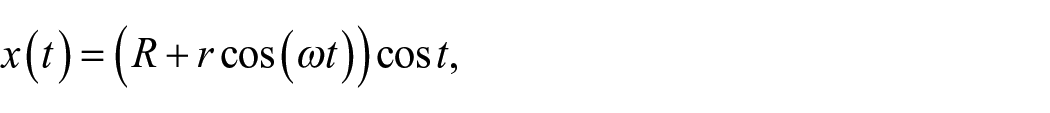
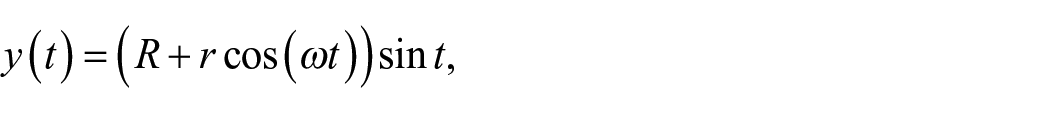

The parameters


(a) Floor plan of ring torus;
The central axis

From relations (10) and (11) it follows
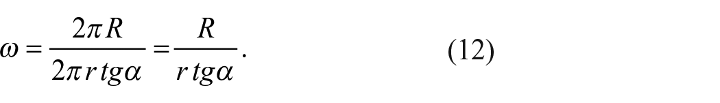
The relation (12) defines the
The required
The arc length part
Let us assign the following values to
In article,
47
it is shown in detail that the
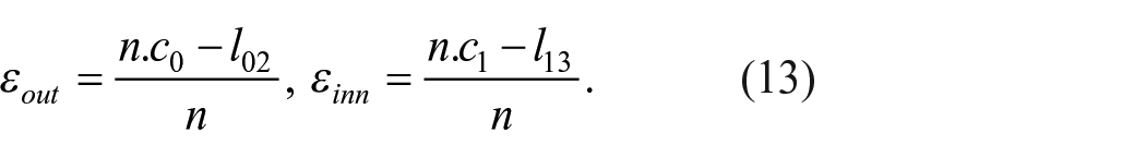
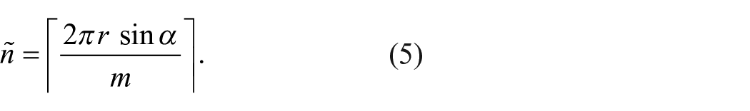
For a given number of used rovings
The
If
If
If
For the given ring torus, toroidal helix parameters, and fixed

For optimal
Similarly, for the given roving width

It is then convenient to calculate overlaps
Based on the derived relations in paragraphs 2.1. and 2.2. the following calculations can be performed for a frame with a straight section and a section created by part of the ring torus. Specified parameters are the following:
Straight section of the frame
Entered: number of
The
2. Determining
3. Determination of
Torus-shaped frame section
1/ Entered:
The
Determining
The
The optimized winding of the rovings on the frame is based on the following principle 49 :
(A) the winding of the frame must not contain a gap,
(B) overlaps of adjacent rovings should be minimal.
Compliance with condition (A) has a higher priority than condition (B).
Based on the above principles, it is suitable to select the appropriate width
Result and discussion
This section focuses on practical examples of using the derived relations in Chapter 2. Attention will be focused on determining the optimal width of the wound rovings, the optimal number of rovings used during winding, and the possible gaps (Figure 10) and overlapping rovings resulting from winding adjacent rovings. 49 The vertical cross-section of all frames referred to in this chapter is circular. The calculation will be carried out successively for a straight frame, a ring torus frame, and a frame composed of two straight arms connected by a quarter-torus part.

Carbon fiber reinforced layers; (a) Homogenous fiber distribution. (b) Layer with gaps (marked by arrows).
An enlarged image of the roving winding on the frame is shown in Figure 10. Subfigure (a) contains a homogeneous winding, while subfigure (b) contains gaps.
The width of the roving primarily depends on the number of used filaments. The most frequently used rovings for winding technology are 24K (24,000 fibers, 9–10[mm] width) and roving 12K (12,000 fibers, 5–6[mm] wide). Roving filaments of 6K (6000 fibers) or 3K (3000 fibers) are arranged in strands and are more suitable for braiding technology.
Figures 11 to 15 are photographs of real windings. In accordance with Notes 2 and 3, the winding was done with green and blue tapes (to color distinguish adjacent tapes) with a rectangular cross-section. Therefore, when using color tapes, the following is indicated as “roving/tape.” The conclusions drawn from the tests and concerning the winding angles, gaps and overlaps of adjacent wound strips are the same as for the rovings with lenticular cross-section.

(a) Winding a layer of eight rovings/tapes on a straight frame (corresponding to the following input values of Table 1: radius of frame

(a) Winding a layer of rovings/tapes on a straight frame (corresponding to the following input values of Table 2: radius of frame

(a) Winding a layer of rovings/tapes on a straight frame (corresponding to the following input values of Table 2: radius of frame

(a) Winding a layer of rovings/tapes on a toroid-shaped frame (corresponding to the following row input values of Table 4: major radius of torus

Example 1 – straight frame
As mentioned, when winding a frame with a circular cross-section, the rovings can be wound at the desired
Width
It is defined
It is fixed
The winding of a fixed number
Calculation of the optimal m roving width at zero overlap of adjacent wound rovings (when

Table 2 contains calculations of the optimal
Calculation of the optimal

Figures 12 and 13 show the winding of rovings/tapes on a straight frame corresponding to the fourth and fifth rows of Table 2.
Example 2 – closed frame – ring torus
The winding of rovings on the curved frame of the ring torus part is solved in this example. For simplicity, the entire ring torus is considered in the example. Let the values
The
Specified
Specified
Table 3 contains the calculation of the optimal
Calculation of the optimal m roving with zero overlap at the external circle

Determination of the optimal number
Determination of optimal number

Figure 14 shows the winding of rovings/tape on a ring torus frame corresponding to the fifth row of Table 4.
Example 3 – curved composite frame
The winding of a composite frame composed of two arms connected by a quarter torus is solved in this example. The frame will be wound at an angle
Determination of optimal number

All three parts of the frame in Table 5 are wound with the same rovings for the specified winding layer. The optimal number
The zero overlaps of adjacent rovings are usually considered using the relations in Chapter 2 (especially relations (4) and (13)). In practice, it is possible to consider the roving width m-1 [mm] instead of m [mm] and thus require an overlap of 1 [mm] instead of zero overlap.
The verification/validation of the correct winding of the rovings in the examples in this chapter can be done as follows. The correctness of the winding angle
Conclusion
The fabrication technology of a specific type of polymer composite frame by winding of fibers is based on the experience of specialists in composite materials and the outputs of the software modeling tools used. The mathematical modeling of the loading of the composite frame determines the geometric shape of the composite, the number of wound layers formed by the fiber reinforcement, and their material composition. The usual materials based on fibers are carbon, glass, and aramid rovings, or their combination. When combining materials, rovings made from recycled materials are also increasingly used. The outputs of modeling also include the required winding angles of the individual winding layers depending on the load on the composite frame.
However, some output requirements may be difficult to meet in the practical process of fabrication of a composite frame. Compliance with the required winding angles can be difficult with more complicated frame geometry. Similarly, achieving windings without gaps and large overlaps of adjacent rovings is difficult, especially for curved frame parts. If the curved frame section forms part of the ring torus and the aspect ratio of the corresponding torus is large, the winding is complicated.
The theoretical outputs of the paper can be the basis for the initial design of composite reinforcement (material and type of roving) for layer winding. With a fixed number of rovings (determined by the number of coils on the rotating ring of the winding head), the optimum width of the fiber roving can be determined. Similarly, for a given number of rovings used in winding the fiber layer, the optimum width of the rovings used can be calculated. For a desired winding angle, a specific roving width, and a number of rovings, the mathematical relationships presented in this article can be used to determine exactly whether a gap or overlap will form when two adjacent rovings are wound and calculate its size. Calculations can be performed for frames containing straight sections and sections forming a ring torus part. The calculation procedure allows for avoiding the trial-and-error method, and based on the technological, design, and material inputs, a qualitatively homogeneous fiber reinforcement/layer for the future composite part can be obtained.
Footnotes
Declaration of conflicting interests
The author(s) declared no potential conflicts of interest with respect to the research, authorship, and/or publication of this article.
Funding
The author(s) disclosed receipt of the following financial support for the research, authorship, and/or publication of this article: This article was supported by the project “Modular platform for autonomous chassis of specialized electric vehicles for freight and equipment transportation,” Reg. No. CZ.02.1.01/0.0/0.0/16_025/0007293, Technical University of Liberec (TUL). Also, the authors appreciate the support of Chair of Composite Materials and Technical Mechanics, Faculty of Mechanical Engineering, Universität der Bundeswehr München (UniBW) through the project “Development of Concept and Materials for a Space-adapted Hydrogen Tank for Efficient Integration in Aircraft,” under the guidance of German Aerospace Center (DLR), which is financed by the “Bundesministeriums für Wirtschaft und Klimaschutz” – registration number 20E2204C. The financial support by Universität der Bundeswehr München for Open Access publication is also acknowledged.