
Abstract
Various types of additive manufacturing (AM) methods (also called 3D printing), and materials have been increasingly studied in the field of additive manufacturing of flexible structures such as fabrics, and flexible electronics. Polymer-based AM processes allow the flexibility, rapid, and low-cost fabrication of complex geometries depending on the types of materials used. The purpose of this review article is to summarize the major AM methods, materials, and their emerging applications to additively manufacture the flexible structures. In the AM methods section, Fused Deposition Modeling (FDM), and Selective Laser Sintering (SLS) are reviewed for fabrics, and Direct Ink Writing (DIW) for electronics. In the Materials section, the manufacturing methods, chemical structures, properties, advantages, and limitations of some of the widely used materials in three-dimensional (3D) printing of polymers are reviewed. Third, the applications of these methods and materials for fabrics, and electronics are covered. Finally, the associated opportunities and challenges in 3D printing process of flexible structures are described. The future research should be related to the exploration of combinations and development of innovative materials, printing process parameters, detail study on improving the properties, and hybrid 3D printing process.
Introduction
The international standard ISO/ASTM 52900 defines additive manufacturing (AM) as a “process of joining materials to make parts from three-dimensional (3D) model data, usually layer upon layer”.
1
AM methods are classified into seven categories: material extrusion, material jetting, binder jetting, sheet lamination, vat photopolymerization, powder bed fusion, and directed energy deposition.
1
These methods are further classified into sub-categories depending on the type of materials used and the process of material deposition. The materials may be in the form of powder, filaments, liquid, hydrogels or ink, and sheets.
2
In this method of manufacturing, materials are added layer upon layer forming a 3D solid object. A computer-aided-design (CAD) model is developed and sliced into several layers by using a slicing software. The generated model is saved as ‘g-code’ which is finally used by the 3D printers to produce the solid object. The schematic diagram showing the working principle of AM processes using unit material is shown in Figure 1. Schematic diagram of working principle of additive manufacturing process (Modified after ref. [8]).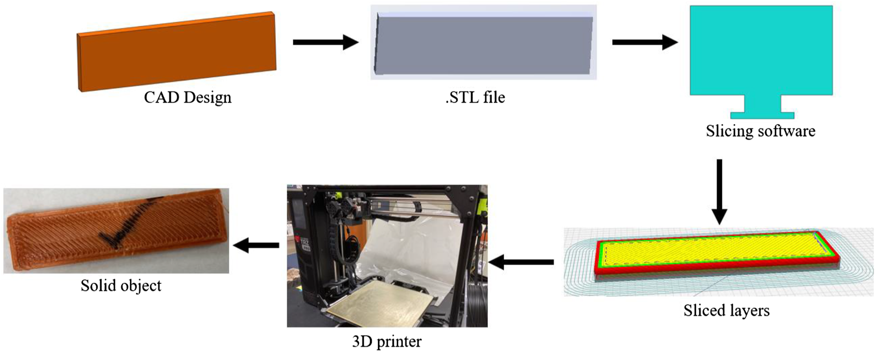
The conventional manufacturing methods such as subtractive machining, casting, forging, and powder metallurgy2,3 take longer time and produce waste. As a result, the cost of fabrication and final product becomes higher whereas AM methods fabricate the parts in a minimal time with little or no wastes.2,4,5 Another aspect is the diverse forms of material availability, which is accelerating its applications in many industries and becoming an integral part of modern product development.4,6 AM methods are mostly used in automotive, aerospace, textiles, pharmaceuticals, medical, tissue engineering, flexible electronics, and sensors. This has increased the competition in the world economy. 7
In recent years, AM methods have attracted attention to fabricate flexible structures such as fabrics and flexible electronics. The main conventional methods of fabric production are weaving, knitting, braiding, tufting and nonwoven manufacturing. 9 Among all these methods, weaving is the most common method, in which warp and weft yarns are interlaced in a defined pattern. A particular fabric manufacturing method is used according to the required fabric design. All of the traditional fabric manufacturing processes consume a lot of time and generate wastes. This is one of the reasons that has attracted the attention of the AM researchers. Similarly, the research on flexible and wearable electronics is fascinating. 3D printing has made it possible to integrate functional electrical/electronic components into 3D printed products, such as sensors, and circuits. The expansion of 3D printing has opened the way for exciting new applications, and opportunities. It has been possible to 3D print stretchable, flexible, and bio-compatible electronic devices which can be adjusted over the irregularly shaped mounting surfaces. In summary, AM has offered great potential and unique capabilities to fabricate parts with multiple functionalities.10–13
This review paper is organized into different sections. In the Additive Manufacturing (3D Printing) Methods section, the working principles and schematic diagrams, advantages, limitations, prospective applications, and summary of the three methods that are the most widely used for 3D printing of flexible structures are described. In the Materials section, the production, chemical compositions and structures, properties, advantages, and limitations of the materials are presented. The Applications section is divided into two parts. The first part covers the application of 3D printing methods to produce flexible fabric structures, whereas the second part includes the 3D printing methods to produce flexible electronic structures. The associated challenges and future opportunities are discussed as well.
Additive manufacturing (3D printing) methods
With the advancements of AM technology, its applications have been widely explored in various fields. Different methods are exploited by the researchers, manufacturers, and innovators. Some of the methods that are used in 3D printing of flexible structures such as fabrics, sensors, and electronics are briefly discussed in this section. The methods reviewed in this paper are highlighted in Figure 2. FDM and SLS methods are reviewed for 3D printing of fabrics, and DIW for 3D printing of flexible electronic components Summary of different additive manufacturing methods.
Fused deposition modeling
Fused deposition modeling (FDM) method works on the principle of material extrusion as shown in Figure 3. In this method, a thermoplastic polymer is melted and then extruded through a nozzle on a build platform. The movement of the nozzle depends on the program (g-code) generated by the slicing software for a specific design. The melted polymer is deposited layer by layer and produces the three-dimensional (3D) object. For structures having hanging parts, a water or chemical dissolvable support material is used. Although the AM process produces near-net-shape products, sometimes, it may require post-processing such as support removal, cleaning, and finishing. The post-processing usually improves the properties and aesthetic of the products. Few examples of materials which are commonly used in this technique are poly(lactic) acid (PLA), acrylonitrile butadiene styrene (ABS), thermoplastic polyurethane (TPU), polypropylene, nylon, polycarbonate, polyether ether ketone (PEEK), ULTEM, glass and metals.14,15 Schematic of fused deposition modeling (FDM) method employed to 3D print a cup with support materials.
The main advantages of this method are processability of a wide variety of materials, low maintenance costs, no toxic chemicals involved, rapid production, overall tolerance of 0.1 mm, and easy material change. The main disadvantages are surface roughness, relatively slow process, restricted dimensions, appearance of voids and lower mechanical properties. 16 Some of the approaches to overcome these disadvantages are optimization of 3D printing process parameters and using polymer composite filaments.
Process parameters include layer thickness, raster angle, print orientation, print temperature, infill pattern and density, and others. Durgun and Ertan 16 found that raster angle and orientation affected the surface roughness, mechanical properties, and production costs. In particular, the build orientation exhibited significant effect on surface roughness and mechanical properties of the parts rather than the raster angle. Poor surface quality caused by stair-stepping effect is generally seen in layer manufacturing processes. Several studies show that a smaller layer thickness can bring lower surface roughness but this can increase the production time.17,18 Chacón et al. 19 investigated the effects of build orientation, layer thickness and feed rate on the strength of 3D printed parts. They found that vertical print orientation showed the lowest mechanical properties whereas on-edge and flat orientations the highest. They also observed increase in mechanical properties with increasing layer thickness and decrease with increasing feed rate for upright orientation whereas the layer thickness and feed rate play insignificant role for on-edge and flat orientations.
Several researchers investigated the effect of heat treatment on mechanical properties of 3D printed parts. This method could increase the bonding between the layers and rasters. Avila et al. 20 worked on 3D printing of parts using different materials such as PC, PMMA, and PEEK and investigated the effect of heat treatment at 90% of glass-transition temperature on their mechanical properties. They found an improvement in tensile strength of about 10 MPa for PC, 20 MPa for PMMA and a slight change for PEEK. Yang et al. 21 studied various thermal processing conditions in 3D printing of PEEK materials and found that different degrees of crystallinity and mechanical properties can be found.
Kaynak and Varsavas 22 examined the mechanical performance of neat PLA, glass fiber (GF)-reinforced PLA, and TPU-blended PLA composites using injection molding and 3D printing methods. They used twin-screw extruders and manufactured composite filaments for 3D printing using 10 wt% of TPU and 15 wt% of GF in PLA matrix. Using the filaments obtained, they 3D printed dog-bone specimens and compared their performance with the dog-bone samples obtained from injection molding. They did not find significant differences in their strength obtained from tensile and flexural tests. However, they noticed that the elastic modulus values of 3D printed specimens were slightly higher than that of injection molded specimens due to the stiffening action of the slightly textured structure formed during 3D-printing.
Direct ink writing
Direct ink writing (DIW) is a 3D printing method based on the principle of material extrusion as shown in Figure 4(a); it is also known as Robocasting. As its name suggests, the material used in this method is in the “ink” form, which is highly viscous liquid, and has the ability to retain its shape after deposition. Although it operates on a similar principle as FDM, it has a major difference that it does not depend on drying or solidification of deposited material to retain the shape when the ink exits the nozzle. A different variety of materials or a combination of materials can be used ranging from ceramics, plastics, and food to living cells. Hence it is an extremely versatile technology. Post-processing such as drying, heating or sintering may be required to harden the printed part and improve its mechanical properties.15,23,24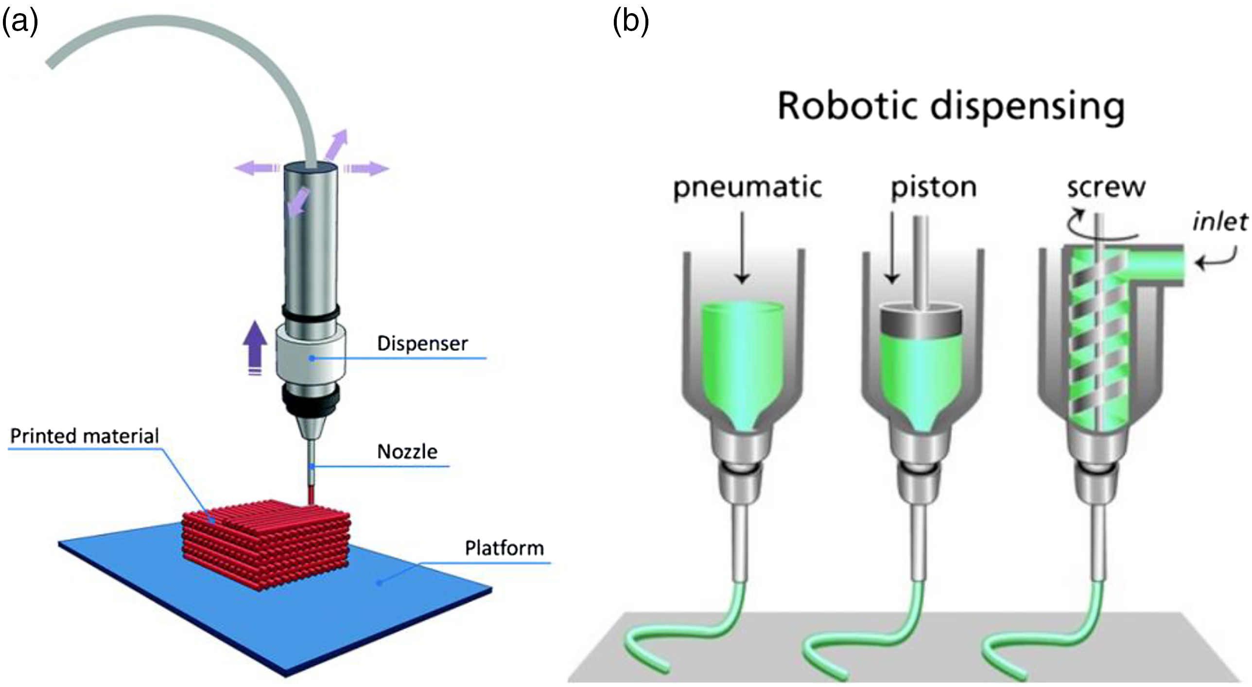
This printing method follows three steps: 3D design, generation of a path file for nozzle and extrusion of ink. After the completion of 3D model in a CAD software, the 2D layer-by-layer or 3D movement path profile for nozzle is generated and exported to the printer. The nozzle moves in a 2D path of each layer generated by the slicing software and deposits the ink layer-by-layer and subsequently builds the 3D object. Alternatively, a 3D object can be printed directly by the movement of nozzle in three dimensions which does not involve a layer-by-layer approach. This method demands specific material strategies to hold the printed structure after deposition. The strategies are: (i) to deploy the intrinsic properties of ink such as the facile oxidation and solidification of liquid metal filaments in air, which can help maintain the 3D structures, and (ii) to fabricate 3D object within a supportive matrix.13,25,26
Depending on the type of material, viscosity and density of ink, and particle size within, the type of dispenser is selected to push the ink through the nozzle. Some common dispensers available are pneumatic, piston, and screw as shown in Figure 4(b). Piston based dispensers provide more direct control over the flow of hydrogel from the nozzle than in the pneumatic dispensers due to the delay of the compressed gas volume. Screw systems provide more spatial control and are useful for the applications requiring ink of higher viscosities to be deposited through the nozzle. However, this method of dispensing can cause a huge pressure drop at the nozzle which can damage the embedded cells. Hence, the design of screw has to be revised in order to make the printing of biomaterials possible. 24
The polymers used for DIW often have limited mechanical properties and experience fatigue under repeated stress, which causes limitations in their applications. This limitation can be addressed by improving the hydrogel used. Gong et al.27,28 introduced the concept of modifying the hydrogel used for fabrication by inducing a double network (DN) structure for various combinations of hydrophilic polymers. The DN hydrogels contained 60–90% water and exhibited a fracture strength of a few to several tens of megapascals and high wear resistance due to extremely low friction coefficients of the gels. Yang et al.
29
demonstrated a two-step method to fabricate a DIW object using DN hydrogels as shown in Figure 5. In the first step, they prepared a 3D printable gel by mixing N,N′-methylenebis (acrylamide) (MBAA), Irgacure 2959, Laponite RDS, sodium 2-acrylamido-2-methylpropanesulfonate (AMPS) and water in specific concentrations. This ink was used to 3D print an object and then cure it with UV light. In the second step, they mixed acrylamide, MBAA, Irgacure 2959, and water and cured the gel prepared. After that, the gel prepared in the first step was soaked in the gel prepared in the second step, and the fully soaked gel was cured again. With various ratio of polyacrylamide to cross-linker, the compressive strength and elastic modulus can be increased to 61.9 MPa and 0.44 MPa, respectively. Similarly, the maximum values of compressive and tensile strength can be obtained up to 93.5 MPa and 1.417 MPa, respectively. 3D printing procedures of DN hydrogels: (a) DIW printing of AMPS network, (b) Curing to get PAMPS network under UV light, (c) Soaking of PAMPS network into acrylamide solution, and (d) Curing of PAMPS/polyacrylamide network.
29
(Reprinted with permission from ref. [29]. Copyright 2017 American Chemical Society.)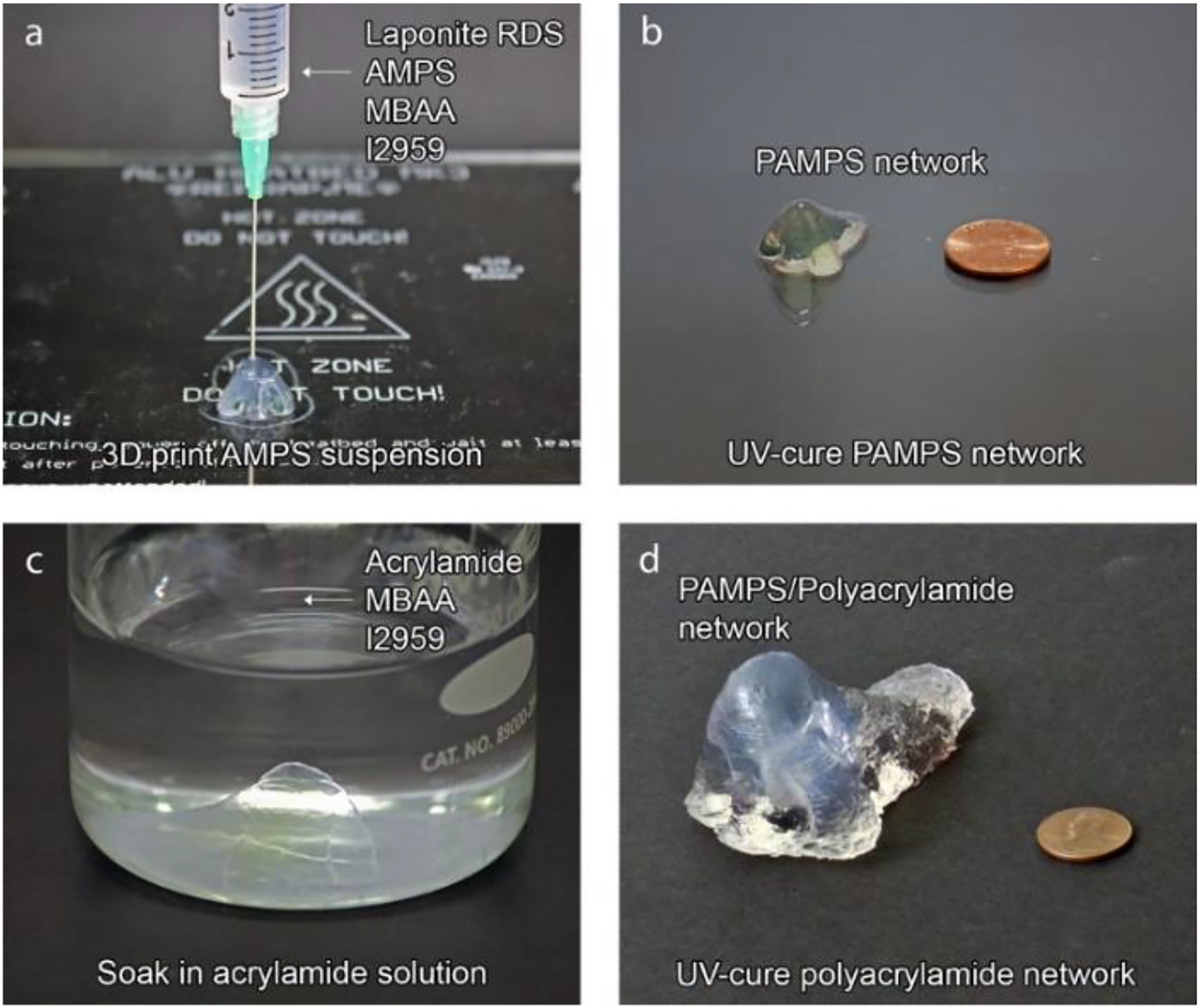
The ink formulation and printing parameters such as ink exiting speed, nozzle size, dispenser moving speed, temperature, and external environment directly influence the final product.
Selective laser sintering
Selective laser sintering (SLS) is a widely used powder bed fusion (PBF) AM technique which uses powder form of materials. In this method, a complex 3D parts can be generated by the fusion of powder material on top of each layer in an enclosed chamber using the thermal energy supplied by a focused laser beam. Following the CAD model, the cross section of each layer is scanned by using a beam deflection system (Galvano mirrors) and then the successive powder layers are deposited having a thickness in the range of 20–150 μm, and is monitored by a powder deposition system.30,31
Figure 6 shows the schematic diagram of a SLS-AM set-up. The SLS-AM system contains laser, mirror scanner, roller, feed container, build cylinder and 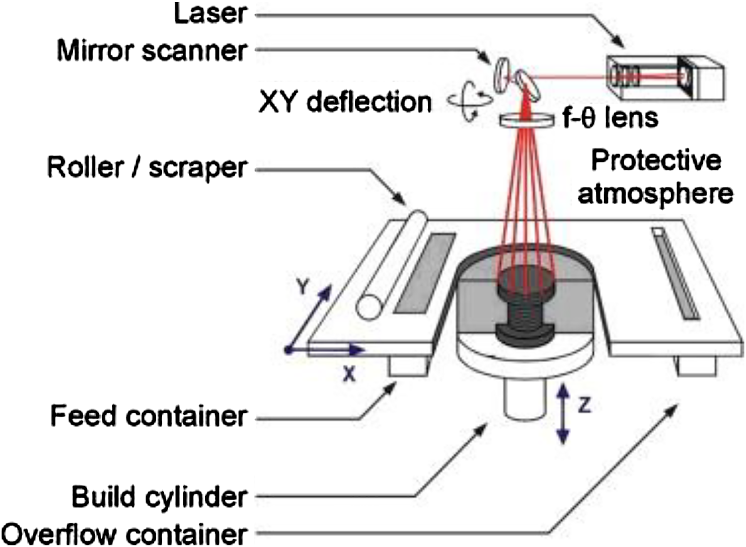
The products manufactured by this method have high dimensional accuracy, which depends on several parameters such as accuracy of the STL model converted from CAD model, cutting into layers, machine resolution, beam offset, layer thickness, material shrinkage, laser beam speed, laser power, temperature of working platform, and hatch distance. The properties of the manufactured products such as surface quality, mechanical properties, dimensional accuracy, and manufacture time can be adjusted based on the printing parameters. Improved mechanical properties can be obtained by improving the sintering between each layer and is dependent on the laser beam density.
33
There must be adequate supply of laser power to get a high-quality product with better sintering between the layers (Figure 7(a)). If the supplied laser power is not sufficient, the powder will not fuse together and in case of higher energy, the products deform, and high dimensional inaccuracy is seen (Figure 7(b)). Hence, the energy density is quite important to consider while working with the SLS method.
Equation (1) represents the equation of energy density required in the SLS method to print a product. It is defined as the amount of energy input per unit area.31,33,34

The powder can be fused together following different binding mechanisms.30,35,36 (a) (b) (c) (d)
Some of the advantages of this method are as follows
37
(i) It is one of the faster forms of 3D printing. (ii) Support structures are not required since the parts are supported by the material powder. (iii) Multiple components can be nested within the powder bed to speed up the production. (iv) The resolution can be achieved to around 0.1 mm. (v) By adjusting the laser power either less or high, different types of material powders such as polymers, metals, ceramics, and glass can be successfully sintered. (vi) Various polymers have been laser sintered to manufacture the products such as TPU, polystyrene (PS), polyester block amide (PEBA), PEEK, and blends of polyamide (nylon), including glass-reinforced grades.
SLS has the following shortcomings
37
(i) Due to the high cost of laser, the machine can be expensive. (ii) Limited availability of different types of thermoplastic powder materials to make the parts. (iii) The manufactured products may have porous surface finish which requires post-processing.
Summary of different 3D printing methods.

Materials
Researchers have explored various additive manufacturing (3D printing) methods. Depending on the method used, the required materials are selected. In this section, an overview of the manufacturing, chemical composition, structure, properties, advantages, and limitations of some of the widely used materials is presented. The materials reviewed in this paper are highlighted in Figure 8. Materials commonly used for different additive manufacturing methods.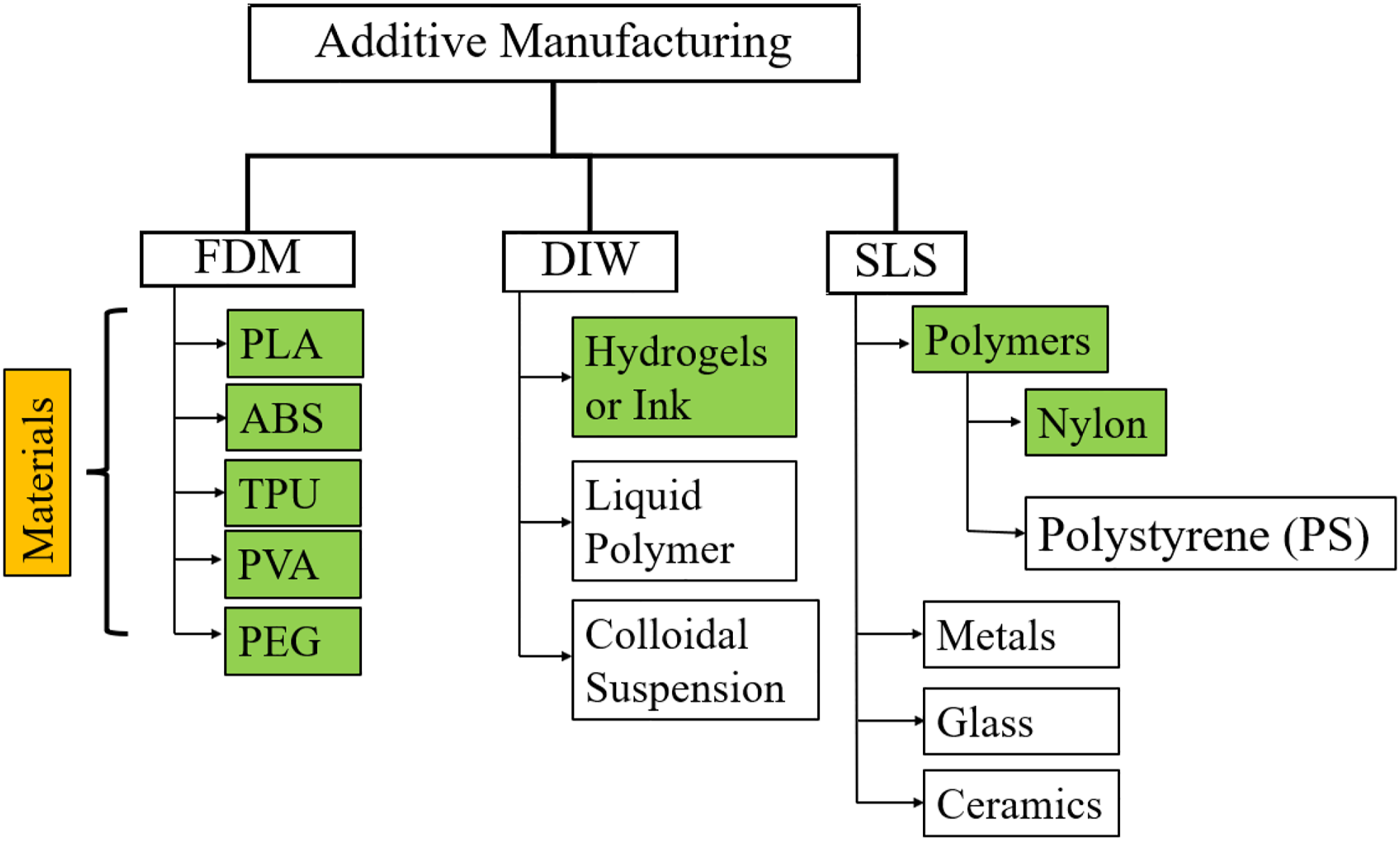
Poly(lactic) acid
Poly(lactic) acid (PLA) is a biodegradable and renewable thermoplastic polymer that is derived from starch obtained from renewable resources such as corn, wheat, rice, and sugarcane.38,39 It has been extensively used in pharmaceutical and biomedical applications, 40 electrochemical energy conversion and storage, 41 packaging and tissue engineering, 42 fabric and fashion industries.14,43–45
Poly(lactic) acid is manufactured by processing and polymerization of lactic acid monomers which exist in two optically active configurations: L (+) and D (−) isomers as shown in Figure 9.46–48 The weight percentages of these isomers directly influences the crystallinity, mechanical properties and degradation characteristics of PLA.
49
If the content of D isomers is less than 2% in the L-D blends, then a highly crystalline PLA can be obtained whereas if it is higher than 20%, a highly amorphous PLA can be produced.47,50 Hence, these lactides are mixed in an appropriate proportion to produce either semi-crystalline PLLA (poly-L-lactic acid) or amorphous PDLA (poly-D-lactic acid) by a ring opening polymerization process. Chemical structure of L and D isomers of lactic acid (a) and high molecular weight PLA formed by ring opening polymerization (b).
47

The lower glass transition temperature (
Figure 10 shows the Differential Scanning Calorimetry (DSC) curve of a 3D printed PLA material exhibiting the first heating cycle, cooling cycle and second heating cycle for exothermic process in an upward direction. The spectra determines important features of semi-crystalline thermoplastic PLA, such as glass transition temperature DSC curve of a 3D printed PLA showing the first heating cycle, cooling cycle and second heating cycle.
Acrylonitrile butadiene styrene
Acrylonitrile butadiene styrene (ABS) is a popular thermoplastic material in 3D printing which is formed by a systematic polymerization of monomers of 15–35% acrylonitrile (A), 5–30% butadiene (B) and 40–60% styrene (S).
67
The chemical structures of these monomers are shown in Figure 11.
68
Two different phases of ABS terpolymer exist: a continuous phase of styrene-acrylonitrile (SAN) and a dispersed phase of polybutadiene as shown in Figure 12.
69
Monomer units constituting the ABS filament.
68
Chemical structure of ABS: SAN phase of ABS (a), Butadiene rubber phase of ABS (b).
69


ABS is low cost and is used to fabricate lightweight, rigid and molded products.
70
It has good dimensional stability, impact strength, abrasion resistance, low coefficient of thermal expansion and can withstand many chemical reagents.
69
In addition, it is easy to shape but tough to break, as it melts and becomes pliable when heated at 220°C; then, it sets quickly which makes it suitable for 3D printing.
14
The matrix composition, molecular mass, type of rubber, rubber particle size, grafted rubber structure, additive content, volume ratio of rubber to SAN phase determines the properties of ABS. For example, the optimized impact strength can be achieved by controlling the rubber particle size, its distribution and micro-structure. It is hydrophobic and shows an absorption of up to 1.5% of water upon storage in aqueous media due to the presence of residual emulsifier and the polarity of the nitrile side groups.
69
It has a elongation at break in the range of 3–20% and flexural strength up to 48–110 MPa.8,71 It has the following limitations: (a) It does not attach satisfactorily to cold print beds. This results in the distorted products. Hence, it is suggested to keep the bed heated to at least 120°C.
14
(b) Fumes are produced when this filament is melted during extrusion in the nozzle, which is not safe to breathe. That’s why the printer should be kept in a well-ventilated area. (c) It gets fractured by UV radiation if it is used for a long time in the sun.
Thermoplastic polyurethane
Thermoplastic polyurethane (TPU) is a biocompatible, biodegradable and linear segmented block copolymer,72,73 which is synthesized by the reaction of polyols with aliphatic or aromatic diisocyanates. The polyols may be ether-, ester-, and carbonate-based diols with average molecular weight in the range of 1000–3000 g/mol. These polyols form the soft segments of the material whereas the diisocyanates such as diphenylmethane-4.4-diisocyanate (MDI) make the hard segments of TPU by addition of a chain extender such as butanediol. The soft segment interconnects two hard segments and the hard segments are bonded together with the presence of hydrogen bonds and form physical crosslinks.74–76 The chemical structure of the materials showing the hard segments and soft segments are shown in Figure 13. Its properties vary from being a high-performance elastomer to tough thermoplastic polymer.77,78 It gets its rigidity and hardness from HS domains whereas the flexibility and elastomeric behavior is gained from SS domains.
79
It is used for high tensile strength, abrasion resistance, tear resistance, low temperature flexibility and high versatility in chemical structures.
74
It can be used in several applications such as textile, footwear industry, tubing, biomaterials, and adhesives.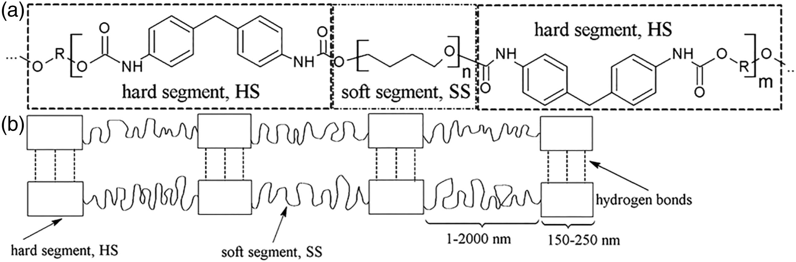
Thermoplastic polyurethane’s easy printability has made it a good candidate to be explored for 3D printing. It provides high flexibility, and strength to the final products. Like most of elastomers, it is melt-processable, recyclable, and elastic. It can be processed by compression, blow, and injection molding and extrusion, which is the basis for fused deposition modeling (FDM) method of 3D printing. 80 It possesses the elasticity of vulcanized rubber as well as the processability of thermoplastics and it can be as soft as rubber or as hard as rigid plastic; thus, TPU bridges the gap between rubber and plastic. 81 TPU suffers from the following limitations:
Poly(vinyl) alcohol
Polyvinyl alcohols (PVA) are non-toxic, water-soluble, bio-degradable, bio-compatible, semi-crystalline, and synthetic polymers which are prepared by polymerizing vinyl acetate following the hydrolysis or partial hydrolysis methods.84,85 Therefore, it can be classified into two groups; fully hydrolyzed PVA (FH-PVA) (1–2 mol% acetate groups) and partially hydrolyzed (PH-PVA) (10–15 mol% acetate groups).
86
The chemical structures of PH-PVA and FH-PVA are shown in Figure 14.
87
FH-PVA has the higher chemical stability, water resistance, and excellent physical and mechanical properties, which have led to its wide use, especially in the textile industry.88,89 PH-PVA is used in packaging for bleaches, bath salts, insecticides, and disinfectants.
86
The properties of PVA are highly dependent on the degree of hydrolysis under acidic or alkaline conditions and the length of vinyl acetate polymer. These properties are molecular weight, solubility, flexibility, strength, and adhesiveness. It is an odorless, tasteless, translucent, white or cream-colored granular powder.
90
Chemical structure of PVA: partially hydrolyzed (a), and fully hydrolyzed (b).
87

The thermoplastic PVA has a glass transition temperature of (a) (b) (c) (d) It does not have cell-adhesive property.
99
Poly(ethylene) glycol
Poly(ethylene) glycol (PEG) is also known as polyethylene oxide (PEO), polyoxyethylene (POE), and polyoxirane.
100
It is a linear or branched, neutral polyether, available in a variety of molecular weights (MWs) from 200 to tens of thousands, and soluble in water, toluene, methylene chloride, and most organic solvents. It is insoluble in ethyl ether, hexane, and ethylene glycol. PEGs having MW less than 1000 are viscous, colorless liquids, water soluble and hygroscopic at room temperature. The higher molecular weight PEGs are waxy white solids. PEG-2000 has a solubility of about 60% in water at 20°C. Its melting point is dependent on its molecular weight and exhibits a plateau at about 67°C.101,102 It is biocompatible,103,104 yields non-immunogenicity, non-antigenicity, protein rejection, and non-toxic. That’s why it has gained popularity among the researchers. The chemical structure is shown in Figure 15. It is most popular in pharmaceutical industries, tissue engineering
105
and medicals. PEG-based wound healing especially in diabetic wounds causes skin cells to grow faster and accelerates the healing.
106
Chemical structure of PEG.
Mechanical, thermal, and chemical properties of materials used in FDM.

Note: ρ: Density; σ: Tensile strength; E: Tensile modulus; ∈: Tensile elongation;
Hydrogels (Ink) for DIW
The printable ink for DIW can be fabricated by mixing fillers, binders, additives, and solvents as shown in Figure 16(a).
25
Valentine et al.
116
prepared two types of ink: insulating ink and conductive ink. For insulating ink, they mixed TPU (Elastollan soft 35A) in cosolvent prepared from 1:4 ratio by volume (v/v) of N,N-dimethylformamide (DMF) and tetrahydrofuran (THF). For conductive ink, they mixed TPU (Elastollan Soft 35A) in DMF and then silver flakes, and APS 2–5 μm (Inframat Advanced Materials) were added. Lastly, the inks were centrifuged to remove the air bubble and made ready for 3D printing. They 3D printed flexible and wearable sensors using DIW method. Images showing (a) Ink formulation and rheology for DIW 3D printing
25
(Reprinted with permission from ref. [25]. Copyright 2019 American Chemical Society.), (b) Ink formulated by using copper nanowires, HDA and water
117
(Reprinted with permission from ref. [117]. Copyright 2015 American Chemical Society.), and (c) Image showing the steps of preparing the additive free ink using holey graphene and water.
119
(Reproduced with permission from ref. [119]. Copyright Wiley-VCH GmbH.)
Jason et al.
117
immersed a bottle containing water in an oil bath heated at 100°C. When the water started boiling, hexadecylamine (HDA) and copper chloride
Wang et al. 118 prepared electrode layer ink by dissolving TPU (Elastollan 35A, BASF) in DMF at 1:1.5 ratio of TPU:DMF. Then, silver microflakes (≈5 μm) were added into the solution and mixed well using planetary mixer. They also prepared sensing layer ink by adding NaCl crystals as the sacrificial template. For this, the grain size of NaCl crystals was reduced to <100 μm, and then mixed with carbon black and TPU (dissolved in twice its weight of DMF). This solution was mixed thoroughly, and a porous and conductive ink was obtained.
Lacey et al. 119 produced additive-free and aqueous carbon-based ink by oxidizing holey graphene (hG), which is a highly porous carbon nanomaterial. They obtained holey graphene oxide (hGO), which is nano porous and hydrophilic in nature. Then hGO was mixed with water at high concentration of ≈100 mm/mL, and hence a printable ink with shear thinning behavior was produced as shown in Figure 16(c). The produced ink was used to 3D print a complex structure, stacked mesh structure.
The composition of inks determines the mechanical properties, resolution, and conductivity of the printed electronics. The inks must possess two important characteristics: shear thinning behavior and viscoelasticity.120,121 These characteristics of inks allow them to extrude smoothly from the dispenser, rapid curing, fusion with previously deposited layers and to maintain a fixed shape of object after printing due to its higher storage modulus and yield strength. 122 In addition, the rheology of inks can be optimized by adding nanomaterials as fillers to improve their electrochemical, conductivity and mechanical properties.
The flow of inks is observed when the applied shear stress (τ) is greater than yield point 
The inks having lower viscosity extrudes easily from the nozzle but have to be cured rapidly to retain the final shape. TPU ink having low viscosity, around 
Nylon powders for SLS
Nylon is a widely used thermoplastic material because of its light weight, excellent mechanical properties, superior flexibility, low moisture absorption, chemical resistant and good dimensional stability.
123
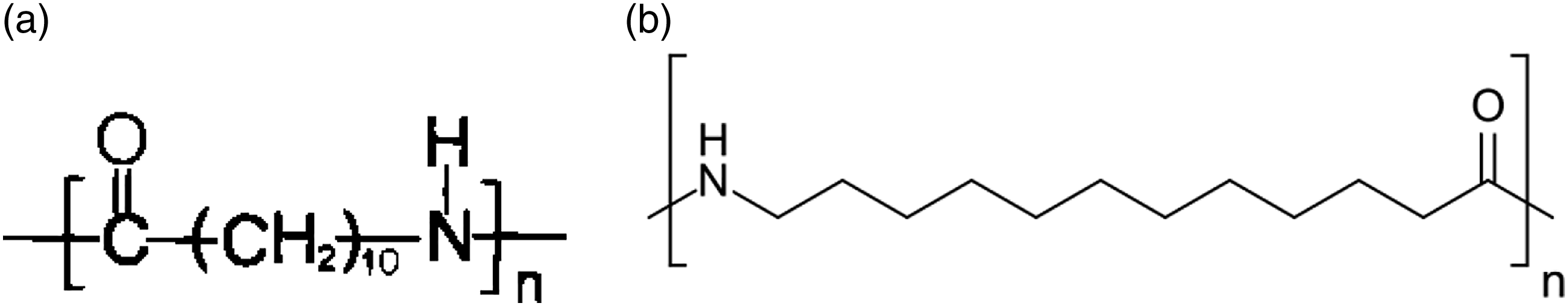
Many forms of nylon are available in market such as Nylon 6, Nylon 11, Nylon 12, Nylon 46, and Nylon 6,6. The semi-crystalline forms of nylon such as Nylon 11 and 12 (Figure 18) are easy to sinter using the SLS method. Chemical structures of Nylon: Nylon 11 (a) and Nylon 12 (b).
124
Nylon 12 can be produced through two routes. These routes are explained briefly.
First route
In this process, the polycondensation of ω-aminolauric acid, a bifunctional monomer with one amine and one carboxylic acid group takes place as follows
124

Second route
In this process, a ring – opening polymerization of laurolactan at 260–300°C takes place, which is carried out by cationic or anionic initiators. The cationic initiators are used commercially since the products formed by it are less stable and oxidized relatively faster than that of anionic initiators. Ring – opening polymerization is widely used method for commercial production as shown in equation (4).
124

The melting temperature of nylon 11 and 12 is 170–180°C. Nylon 12 is used in various industries including as films for packaging materials in the food industry, pharmaceutical and medical fields, sintered powder for coating metals, textile industry and many others.
Higher mechanical properties can be achieved from nylon 11 and 12 than their amorphous forms.
125
This is one of the reasons for being widely used by the researchers with the SLS process. However, shrinkage during crystallization can be an obstacle in production of accurate parts. It provides sufficient time to recrystallize and achieve better products by the proper fusion of newer layers with the older ones.
125
Similarly, molecular weight is important aspect to consider while sintering of polymer. It affects the melting viscosity and hence melt flow index (MFI). Higher MFI is related to lower melting viscosity and lower molecular weight of polymer.
126
The relationship between molecular weight and melting viscosity can be given as
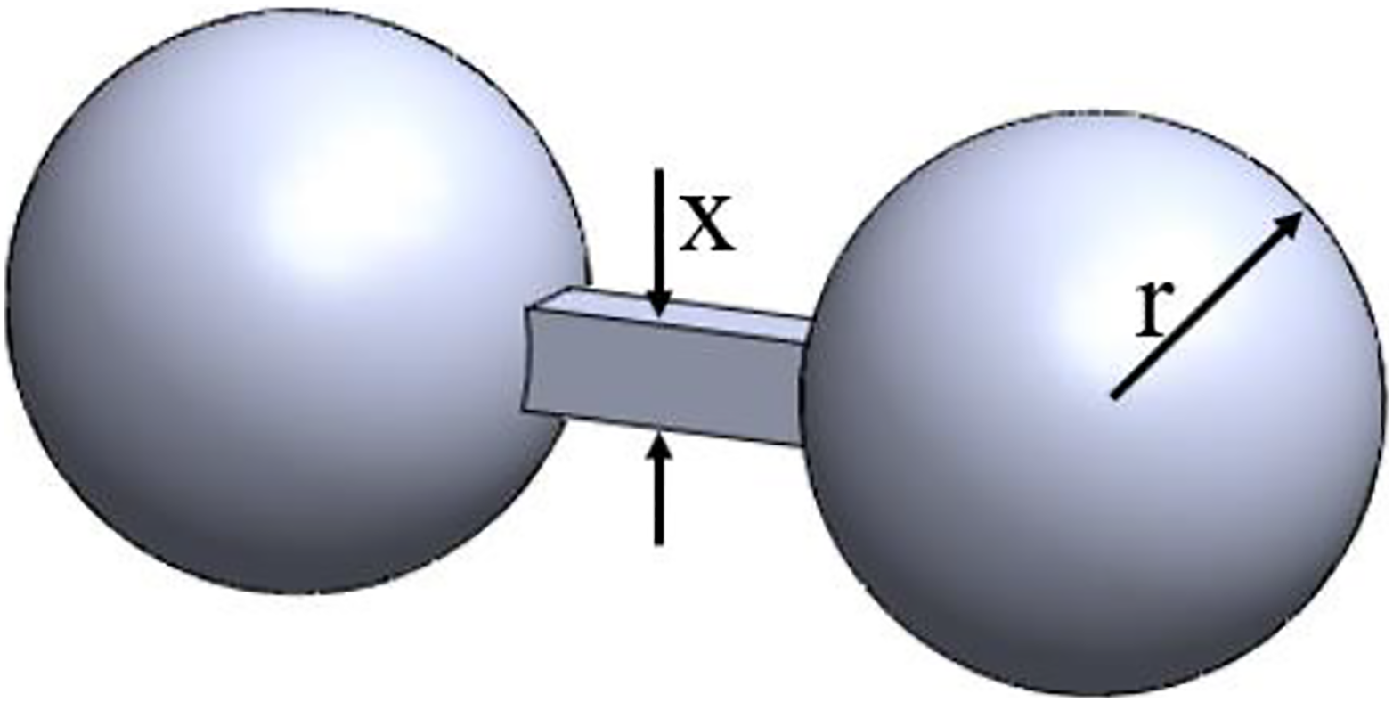
Similarly, for a better SLS process and product quality, Frenkel proposed a model for predicting melting viscosity. This model considers the sintering rate of two adjacent materials and is given by equation (6) and Figure 19.
126
Frenkel sintering model (Modified after ref. [126]).
Applications
In this section, a review of additive manufacturing of fabrics and flexible electronics is presented.
Additive manufacturing of fabrics
Use of different additive manufacturing (3D printing) methods is in its infancy; they have been extensively used in textile and fabrics industries. The most widely used materials are PLA, ABS, TPU, Nylon, etc. The desired traits of printable materials for textile applications are printability, flexibility, biocompatibility, good mechanical, and structural properties. In this section, the application of different 3D printing methods along with the suitable materials for 3D printing of fabrics is presented.
Fused deposition modeling
Fused deposition modeling is the dominating 3D printing technology in fashion, and textile industries. Several researchers worked on design and 3D printing of fabrics by using FDM method. Some of this research is reviewed briefly in this section.
Different designs of fabric structures have been 3D printed using FDM method. Figure 20 shows the design of lattice structures, CAD models and 3D printed fabric structures for plain and twill weave designs. Figure 20(a) shows the design of plain weave fabrics with the spacing between two yarns denoted by Y mm, gap of h mm and diameter of 3 mm. The CAD model and 3D printed structure based on the design when Y = 5 mm and h = 0 mm are shown in Figure 20(b) and (c), respectively. Similarly, the CAD model and 3D printed structure based on the design when Y = 10 mm and h = 0.5 mm are shown in Figure 20(d) and (e), respectively.
14
3D printed fabric structures using FDM. (a) Design of lattice structure of plain weave fabric, (b) CAD model of plain weave fabric when h = 0 in (a), (c) 3D printed plain weave fabric structure when h = 0 mm, (d) CAD model of plain weave fabric when h = 0.5 mm in (a), (e) 3D printed plain weave fabric structure and a yarn when h = 0.5 mm, (f) Design of lattice structure of twill weave fabric, (g) CAD model of twill weave fabric, (h) Top view of 3D printed twill fabric structure and a separated yarn, and (i) front view of 3D printed twill fabric structure.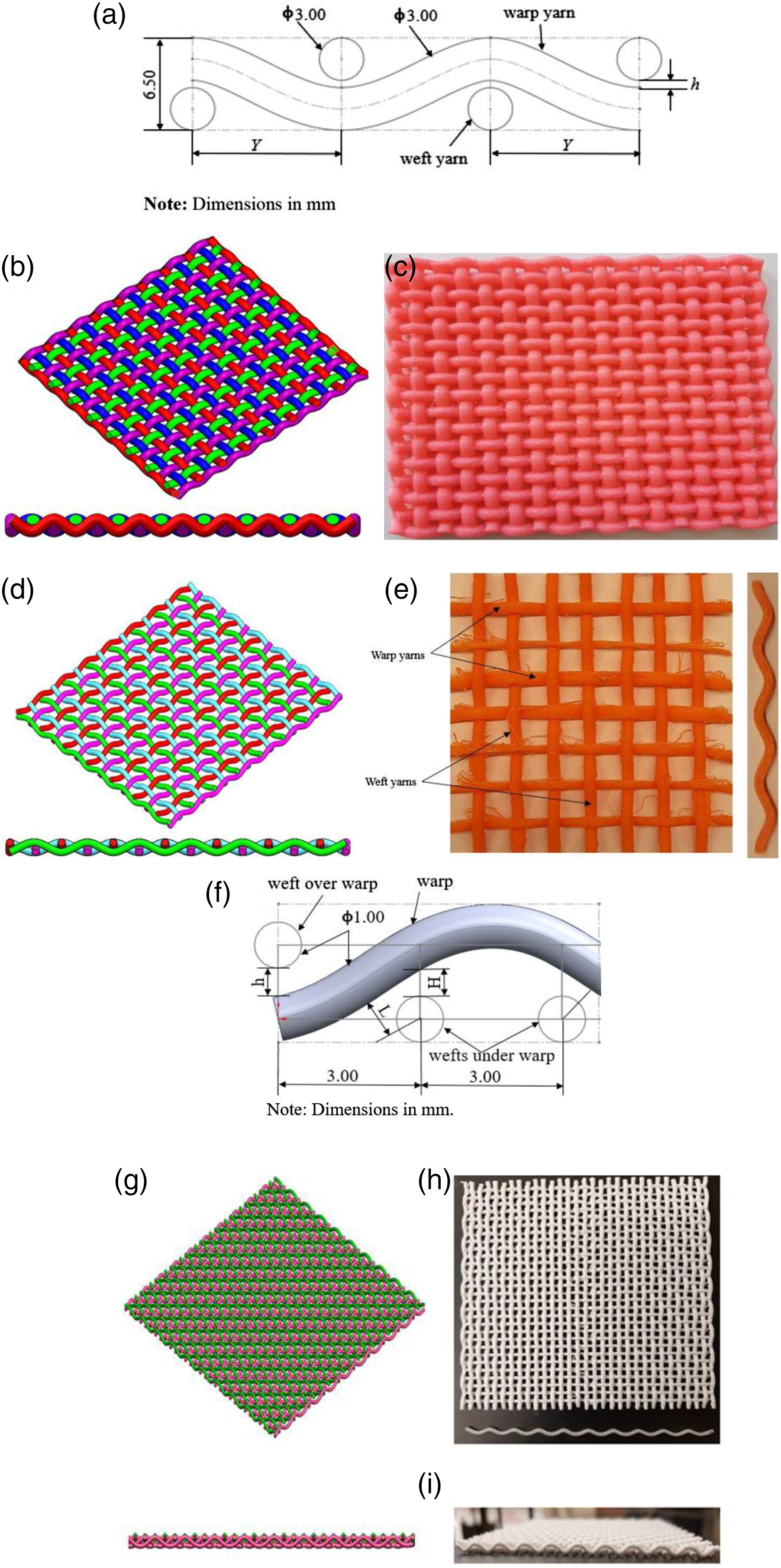
The design of twill weave fabric is shown in Figure 20(f).14,43 The spacing between two yarns is 3 mm and the gaps at the cross-over points are given by H, h, and L. The values were set to H = 0.59 mm, h = 0.65 mm, and L = 0.90 mm. The yarns of 3D printed twill weave fabric were not sticking with each other and easily separated out manually. The CAD model and 3D printed twill structures are shown in Figure 20(g)–(i), respectively. The mechanical tests were performed for twill fabrics. The uniaxial tensile tests of yarns and fabrics showed that the mean tensile stresses at maximum load were 29 MPa and 18 MPa for warp and weft yarns, respectively. The stiffnesses were 415 MPa and 628 MPa for warp and weft yarns, respectively. Similarly, the mean tensile stresses were 32 MPa and 10 MPa for twill fabrics in warp and weft directions respectively. The stiffnesses were 609 MPa and 532 MPa for twill fabric in warp and weft directions, respectively. The flexural tests showed that the flexural strength for twill fabric was lower than the fabric tensile strength; hence, this twill structure could easily fail under bending force than under tensile load.
Weft knitted fabric was designed as shown in Figure 21(a)–(c). Based on the CAD model designed in Solidworks®, the fabric structure has been 3D printed with higher flexibility as shown in Figure 21(d). The yarns are not sticking with each other. The fabric structure was 3D printed as a single piece having flexibility and without any defects on the surface. (a–c) Design of weft knitted fabric structure, and (d) 3D printed weft knitted fabric structure with magnified view.
Melnikova et al.
107
used FDM printer X400 and different types of materials such as PLA, soft PLA, and BendLay. They printed weft knitted structures as shown in Figure 22. Knitted structure was printed using BendLay and with support material. It was realized that support structure was hard to remove, which destroyed the model as shown in Figure 22(a). Hence, they concluded that it was not possible to print a fine model by FDM. However, using soft PLA and without support material, they could obtain the structure having separated loops and exhibiting similar properties to knitted fabrics as shown in Figure 22(b). The surface roughness and fine fibers between loops could be easily observed on a macroscopic level. Weft knitted fabric structure 3D printed by using FDM method: (a) BendLay with support materials, and (b) Soft PLA without support materials.
107
(Copyright 2014 IOP Publishing Ltd).
Spahiu et al.
127
designed a 3D model of fabric as shown in Figure 23(a), in which the shape of structure is an arrowhead with negative Poisson’s ratio having dimensions of 130 mm × 130 mm. A structure having negative Poisson’s ratio is called auxetic structure. They used the material, FilaFlex manufactured by Recreus with shore hardness A82 to fabricate the lattice structures. They printed several lattice structures and then using a Dikale 07A 3D Pen, all the parts were joined with each other in a definite pattern. Finally, a complete 3D printed dress was obtained as shown in Figure 23(b). However, they concluded that more research is needed to achieve the properties of textile materials to replace the traditional way of garment manufacturing. FDM 3D printed fabric structure: (a) 3D modeled lattice structure for fabric, and (b) A complete 3D printed dress over a mannequin.
127
(Copyright 2020 Journal of Engineered Fibers and Fabrics.)
Kim et al.
128
3D printed unit cell of fabric structures using TPU as main building material as shown in Figure 24(a). Their fabric design was inspired by the spider web and used triangles of different sizes and shapes. They designed the final silhouette of the to-be-3D-printed clothing using the software, Rhinoceros and then modelled the fabric structure by using another software, Grasshopper as shown in Figure 24(b). After 3D printing of the unit cells, they assembled them together producing the final 3D printed cloth. They used different connection methods to join the triangles such as sewing, and copper wire. A complete 3D printed dress wrapped over the traditionally manufactured dress is shown in Figure 24(c). (a) 3D printed unit cell of fabric, (b) Design of to-be-3D-printed clothing, and (c) A complete 3D printed dress over a traditionally manufactured dress.
128
(Copyright 2019 Fashion and Textiles).
Uysal and Stubbs
129
used a combination of different materials, PLA and LAY-FOMM 40, to 3D print textile – like structures using the 3D printer X400 such as gloves as shown in Figure 25. LAY-FOMM 40 is made of rubber-elastomeric polymer and PVA component. After rinsing in water, PVA disappears, and the remaining part becomes soft, flexible, and micro-porous. It is harmless and food-safe.
130
First, they printed the sewing patterns (Figure 25A) in which the surfaces were printed partially with polygons (Figure 25B and C) and then the patterns were sewn together to obtain the final 3D form of glove (Figure 25D). The authors suggested two future studies regarding joining the printed patterns: ultrasound technique and 3D printed connections to join the patterns to avoid extra needs of tools.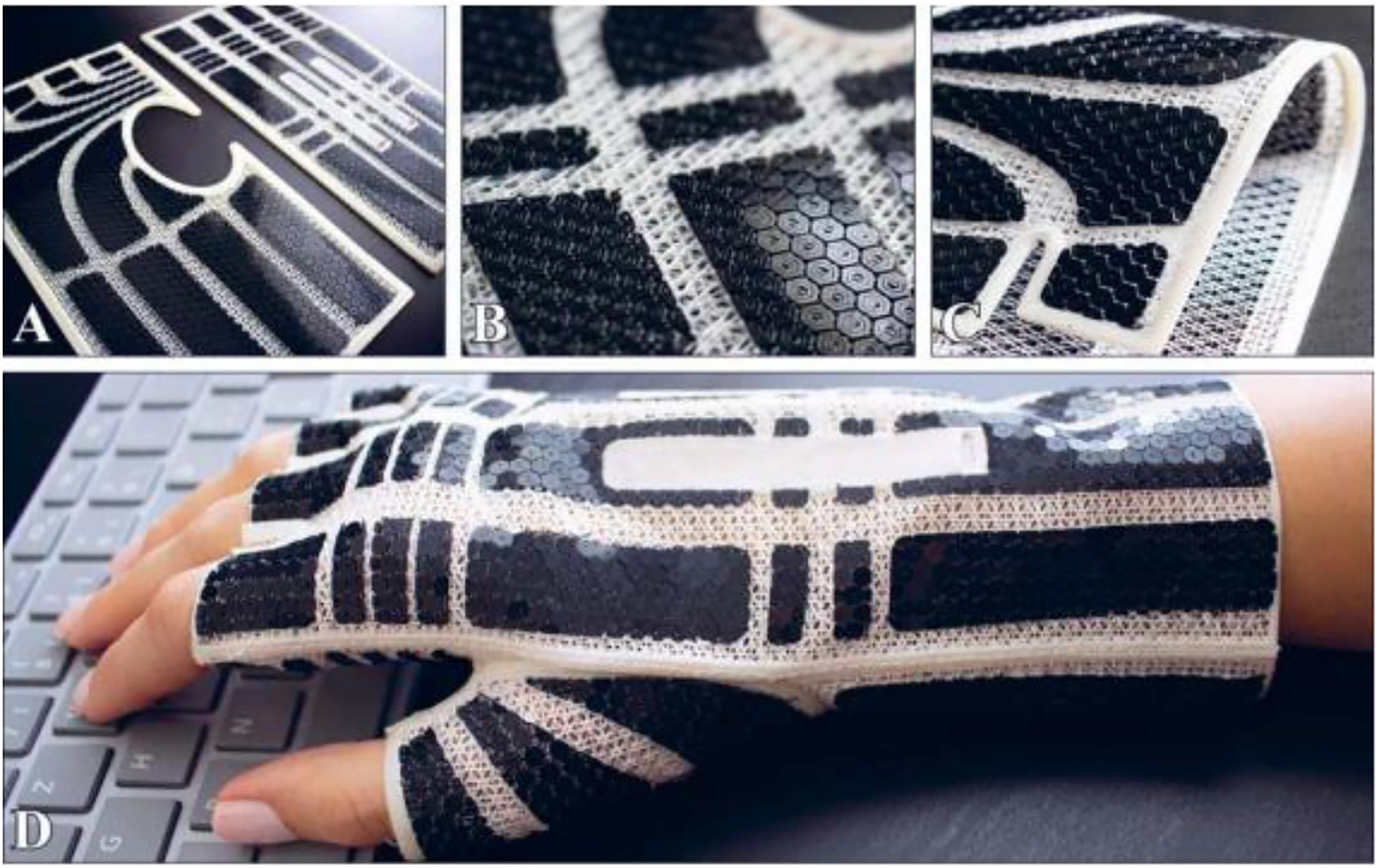
Selective laser sintering
A fashion design company named, Nervous System, 3D printed different fabrics structures following kinematics methods with SLS using Nylon powder as shown in Figure 26. Examples of 3D printed structures include skirt, blouse, belts, jewellery, and many more. The kinematics bodice they produced was composed of 1320 hinged pieces, and was 3D printed in a single folded piece. To adjust the size of bodice into the printer, the fabric was printed in a flattened form which was produced by Kinematics folding software. The 3D printed bodice was wearable straight out of the printer since no pieces were manually assembled and no fasteners were used.
131

Beecroft 3D printed textile-based tubular structures using SLS method.
123
The material employed was nylon powder to produce flexible weft knitted structures. For 3D printing, a CAD model is required which was developed by using Rhino CAD software. The printed samples were manually compressed and stretched without any deformations in the knit, and the compressed and extended lengths were determined (Figures 27(a) and (b)). This tube has a compression and extension range of 95 mm, which is 52.80% of its length. Moreover, the samples were manually stretched over the conical structure repeatedly to determine the stretch and recovery properties of the tube (Figure 27(c)). It was observed that the loop structure recovered its shape but had slight deformations. In addition, each tube was bended and folded manually to see the overall flexibility and the structure recovered to its original shape (Figure 27(d)). Weft knitted textile-based structures.
123
(Copyright 2019 International Journal of Fashion Design, Technology and Education).
Additive manufacturing of flexible electronics
Several research works on 3D printing of flexible electronics have been performed. Some relevant works along with the associated additive manufacturing method are reviewed in this section.
Direct ink writing
Valentine et al.
116
developed a hybrid 3D printing method to fabricate flexible and wearable electronics using insulating matrix and conductive electrode inks. They used thermoplastic polyurethane (TPU) elastomers which acted as insulating matrix. To make it conductive, silver flakes with dimensions of ≈2 μm were added to TPU matrix. These inks can be used to print in a specific layout and then both the active and passive electrical components are merged to obtain the final electric circuit. To combine, vacuum nozzle can be employed to pick up the components from one location and place at another. The conducive traces were printed to make electrical connection between the components. The whole process is shown in Figure 28. They observed a strong bonding between TPU and AgTPU inks, and as a result, delamination, and cracking during or after printing were not seen. This observation solved a common problem of delamination during printing. Schematic diagrams showing (a) DIW 3D printing using an insulating ink, (b) DIW 3D printing using conductive ink, (c) 3D printed wearable and flexible sensor, (d) Pick-and-place of components using vacuum nozzle, (e) Direct ink writing of AgTPU traces, and (f) A functional LED device worn on a finger.
116
(Reproduced with permission from ref. [116]. Copyright Wiley-VCH GmbH.)
The conductivity of a composite conductive ink with respective to power-law theory for a percolating network is given by
Boley et al.
132
used direct ink writing method to fabricate novel stretchable strain gauges. They employed Gallium-Indium alloys such as eutectic Ga-In (EGaIn) (75% Ga, 25% In) as the ink and extruded over two silicon – based substrates: glass and Polydimethyl-siloxane (PDMS) mixed in 10:1 weight ratio. The printing setup is shown in Figure 29(a)–(c). The ratio of the velocity of the EGaIn exiting the needle to the stage velocity, v* can be expressed by Direct ink writing of stretchable electronics: (a) DIW equipment, (b) schematic of DIW process, (c) Detailed cross-sectional view of deposited ink, (d) 3D printed stretchable strain gauge using DIW method. Scale bar is 5 mm in length, (e) Comparison of performance characterization of DIW 3D printed strain gauges at 50% and 100% strain loops repeated for five cycles, and (f) Strain gauges stretched at different strains.
132
. (Reproduced with permission from ref. [132]. Copyright Wiley-VCH GmbH.)

Challenges and opportunities
Additive manufacturing methods allow to produce complex structures depending on the CAD model. The structures may be a topology of an internal architecture of a part or the whole geometry. With high degree of design and fabrication freedom comes the associated challenges and opportunities for the researchers and innovators.3,133 The challenges include representation, optimization, material selection, material development and 3D printing of complicated geometries.
Since the research field related to additive manufacturing of fabrics is new, it carries a lot of challenges to overcome to make an impact on human lives. (a) The fabric structures have complex architecture, which needs a good design knowledge in CAD software. An experienced design engineer needs to be involved. (b) The lattice structure may contain gaps between the yarns and have weaving curves. This makes the rapid prototyping of such structures a challenging task. Many printing parameters such as printing orientation, temperature, speed, infill density, and layer thickness need to be studied. (c) The materials available are PLA, TPU, ABS or other thermoplastics. The resulting fabrics using these materials do not possess the required fabric properties such as flexibility and strength. Hence, novel material development and its adoption to the additive manufacturing should be pursued. (d) Most of the 3D printers are designed to fabricate parts of limited size. This brings a challenge to produce fabrics of larger size. Moreover, it is a challenging task to connect or join or stitch all the smaller parts. Therefore, research on stitching of parts is important.
All these challenges, on the other hand, bring opportunities for the innovators and scientists. The additive manufacturing of flexible structures is interesting and revolutionary. It can be used to produce support structures for fabrics along with the fabrics manufactured by traditional methods.
Some of the challenges and opportunities associated with the 3D printing of electronics are as follows: (a) To maintain the same conductivity of the 3D printed electronics is still challenging. The reason is the poor conductivity of ink which is caused by low curing temperature because of the limitation of substrate material such as cardboard, polymers. In addition, the available material types and their processing to 3D print electronic objects is also one of the major difficulties. Hence, it is recommended to explore different materials to provide adequate functionality and manufacturability for the product. Moreover, a hybrid 3D printing process should also be studied. A hybrid process combining FDM and direct ink writing shows higher applied potential, and more flexibility.
10
For example, a shoe insole was 3D printed by using multi-materials, which had embedded pressure and temperature sensor, and mounted with wireless communications chip for data transmission (Figure 30). The multi-layer sensors along with the insulating layers and sensing elements have been printed using hybrid printing method. This has made possible with the combination of ink jet, aerosol jet and extrusion print heads.
10
Along with all these challenges, the innovative eyes can see the opportunities. For example, one can combine 3D printed electronic elements such as sensors in the completely 3D printed fabrics. (b) One of the major challenges is to maintain the resolution of printed electronics, which directly affects their performances. An electronic component with higher resolution works better than that with lower resolution. This hinders the wider adoption of additive manufacturing technologies in electronics [134] [135] [136]. (a) 3D printed shoe insole with embedded pressure and temperature sensors with wireless communications chip for data transmission, and (b) Data generated from the chip embedded in the 3D printed shoe insole.
10
(Copyright 2018 Opto-Electronic Advances.)

Conclusions
In this paper, several AM methods, and materials are reviewed, which have found applications for fabrication of flexible structures such as fabrics and electronics. AM is transforming the manufacturing industries providing the capability to fabricate objects ranging from simple to complex geometries. It has been adopted in almost every industry for fabricating prototypes or for research work. A group of researchers have started working on 3D printing of fabrics. Based on the design requirements, different types of fabrics have been investigated for a wide variety of materials available. The designs of fabrics studied are plain and twill weave, knitted, or some other innovative designs. The additive manufacturing methods explored are fused deposition modeling (FDM), and Selective Laser Sintering (SLS), which have been discussed in this article. The most common materials used are PLA, ABS, TPU and nylon. However, a detail study on the mechanical properties of printed fabrics is still not seen in the literature. Moreover, the literature also lacks studies on printing process parameters. This creates a future research direction on 3D printing of fabrics.
In the second part, the fabrication of electronics is discussed. There are many methods for 3D printing of electronics, but in this review the material extrusion based direct ink writing (DIW) method is discussed. This method uses the hydrogel or ink form of materials and extrudes through the nozzle based on the CAD model. The printable ink for DIW can be fabricated by mixing fillers, binders, additives, and solvents. It is useful for a wide variety of materials such as ceramics, plastics, food and living cells. Hence, it is an extremely versatile technology. Post-processing such as drying, heating, or sintering may be required to harden the printed part and improve its mechanical properties. It fabricates flexible and wearable electronics using the insulating matrix and conductive electrode inks. However, the poor conductivity, limitations of material types available, and resolution of 3D printed electronics are some of the difficulties. A future work can be on increasing the conductivity, explore different combinations of materials and/or develop innovative materials, and increasing the resolution of 3D printed electronics.
Footnotes
Acknowledgements
This work has been supported by the Department of Mechanical Engineering at Auburn University, which is appreciated.
Declaration of conflicting interests
The author(s) declared no potential conflicts of interest with respect to the research, authorship, and/or publication of this article.
Funding
The author(s) received no financial support for the research, authorship, and/or publication of this article.