
Abstract
Natural fiber reinforced composites are becoming popular in various industrial and commercial applications as structural components. Unlike conventional materials, machining of fiber composites is critical due to its heterogeneous structure. Hence, it is necessary to understand the machining behaviour of fiber reinforced composites. Hybrid composites reinforced with banana fiber and fly ash filler in polyester matrix were fabricated and then evaluated for drilling performance. Drilling experiments were performed using the Taguchi L27 orthogonal array. The influence of feed rate (A), cutting speed (B) and filler content (C) on thrust force, surface roughness, and delamination factor entry and exit were using Taguchi and Analysis of variance (ANOVA) techniques. The results revealed that (i) Minimum thrust for attained at filler content (A) 1 vol %, speed (B) 3000 r/min, and feed (C) 100 mm/min, (ii) Minimum surface roughness at filler content A (3 vol %), speed B (2000 r/min), and feed rate C (100 mm/min) and (iii) Minimum peel up and push out delamination at filler content (A) as, 5vol %, speed (B) 2000 r/min, and feed (C) 100 mm/min. This study provides machining insights on agro-industrial waste based polymer composites for structural applications.
Keywords
Introduction
Development of eco-friendly materials is a challenge for material scientists due to their non-compromising characteristics of strength and durability along with weightlessness, economic viability and the facilitation of global sustainability. Interest in the usage of renewable resources ensured a wide range of applications in the polymer composite sector which is dominated by synthetic materials.1–4 Machining is identified as the most suitable method to fabricate polymer composites with holes and slots without affecting reinforcements which facilitate complex geometry requirements. 5 The heterogeneous nature of fiber composites strongly influences machining performance compared to conventional materials. Machining procedures of fiber composites are complicated and differ from conventional materials due to the evolution of fiber crack, delamination, fiber exposure, and matrix flow. 6 Drilling is an important manufacturing process required for assemblage through component fastening. Hence, it is unavoidable and necessary to investigate such materials. 7 Bio-fiber composites exhibit different characteristics while drilling due to their anisotropic and heterogeneous nature. Fiber pull-outs, delamination, and chipping are important drilling mechanisms due to elevated drilling forces and prevailing temperatures. Interfacial adhesion between the hydrophobic and the hydrophilic nature of the matrix/fiber also influences drilling quality. 8 Bio-fibers, namely banana, coir, linseed, hemp, jute, kenaf, luffa, pineapple, sisal, sugarcane bagasse, etc., are available abundantly from renewable resources. Bio-fiber advantages include low density, low cost, reduced health risks, reduced tool wear, and being biodegradable compared to conventionally available reinforcement materials.9–12 Natural fiber composites have applications in the automotive, aerospace, door decor, flooring, roofing, sporting equipment, packaging industries and construction sectors, and in architectural components.13–15 Hybrid composites are composed of two or more reinforcements in a neat single resin. Reinforcements can be of fiber to fiber, filler to filler, or fiber to filler. Hybrid composites with natural fiber reinforcement and industrial waste offer two important advantages. The first is the conversion of industrial waste into useful products and the second the evolution of enhanced mechanical properties through utilization of agro-waste reinforcements.16,17 Delamination and fiber pullout mechanism of drilling influences composites performance. Hence, it is necessary to study the drilling characteristics of composites to improve overall performance. Composites enhanced material performance and improved mechanical properties are possible by adding fillers of low cost. 18 Delamination is the most critical failure mechanism while machining can be minimized by adding fillers and choosing optimum machining parameters. 19 Among various agro wastes, banana accounts for about 27.55 million tonnes/year of surplus residue generation in India using leaves and pseudostems. 20 Fly ash is the major solid industrial waste produced in India and accounts for about 226.13 million tons. These agro and industrial solid wastes can be effectively utilized as reinforcements in polymers to develop new and sustainable low-cost composites. 21
Sadayan et al. 22 evaluated the torque and thrust force on sisal fiber reinforced vinyl ester composites with coconut shell filler. Results revealed that a predrilled hole of 0.4 mm or above reduced thrust force drastically. It was also observed that increased fiber volume and feed increased thrust force. Parthipan et al. 23 investigated the drilling characteristics on kenaf fiber (50 vol %) reinforced epoxy composites with the effect of silane treated silicon oxide nanoparticles (0.5, 1, 2 vol %). Composites with 2 vol% of silicon oxide provided better dimensional stability. Sumesh et al. 24 analysed the machinability of pineapple/flax fiber reinforced epoxy hybrid composites with incorporation of cellulose micro filler. Results revealed that better machinability was attained at 2 and 3 wt% of cellulose micro filler addition on hybrid composites. Vikas et al. 25 evaluated drilling forces on glass fiber/epoxy composites filled with agro wastes (coconut coir, rice husk and wheat husk) using neural network modelling. It identified that axial thrust and torque increased with an increase in feed for all speeds for twist/parabolic drill bits. Arun Premnath 26 performed drilling on carbon fiber epoxy composites with nano silica particles. Response surface methodology based drilling study identified that increased feed rate and weight percentage of nano silica increased thrust force and delamination factor. Optimum thrust force of 38.67 N, pull and push delamination 1.070 & 1.188 were obtained with a combination of low feed, low speed and low wt% of nano silica respectively.
Sandhyarani et al. 27 examined the influence of coupling agent, fiber type and direction, spindle speed, feed rate, drill material and diameter on compression moulded jute fiber reinforced polypropylene composites. The results revealed that minimum thrust force and delamination was observed in the specimens without coupling agent and transversely oriented 40% fiber content with the drilling parameters of low feed rate, high spindle speed and 4 mm Co-HSS drill. Lilly et al. 28 investigated the effect of machining process parameters such as speed (1000, 2000 & 3000 r/min), feed rate (15, 20 & 25 mm/min) and drill diameter (4, 6 & 8 mm) on thrust force during drilling of pineapple fiber reinforced epoxy composites. From the results, it was observed that Increase in feed rate and decrease in spindle speed results in increased thrust force. Experimental results were optimized using genetic algorithm, the results stated that minimum thrust force attained at feed 15 mm/min, speed 2993 r/min and 4 mm drill diameter. Rajaraman et al. 29 studied the effect of process parameters on drilling of kenaf and banana fiber reinforced epoxy composites. The results stated that delamination of the composites was critically controlled by feed rate. Minimum delamination attained at feed rate of 150 mm/min and speed of 3000 r/min. Jani et al. 30 analysed the machinability of hemp/kevlar (64:40 wt %) fiber composites hybridized with palm and coconut-shell filler materials. The investigation concluded that addition of fillers resulted in enhanced surface quality without fiber pullouts and delamination. This justified the fact that excellent engineering products can be manufactured using filler addition. Fly ash particles augmented by carbon fiber reinforced epoxy composites were experimentally investigated for drilling operations. 31 Control parameters which included fly ash content (5 & 10 wt %), spindle speed (1000, 2000 & 3000 r/min), feed rate (50, 100 & 150 mm/min), and drill diameter (6, 8 & 10 mm) were optimized using grey relation analysis. The investigation revealed that minimum thrust force, delamination, and surface roughness were achieved with 10wt% of fly ash, spindle speed of 3000 r/min, drill diameter of 8 mm, and a feed rate of 50 mm/min. The investigation concluded that fly ash particles contributed to enhanced machinability. Pailoor et al. 32 investigated the drilling on jute fiber-reinforced polypropylene composites manufactured using in-line compression molding. Fiber direction (longitudinal & transverse), coupling agent (with & without), fiber content (20, 30 & 40 wt %), fiber type (chopped & continuous), spindle speed (600, 1260 & 270 r/min), feed rate (0.1, 0.2 & 0.3 mm/rev), drill diameter (2, 3 & 4 mm), and drill material (HSS & Co-HSS) were the different influencing parameters and levels used in this study. The analysis was done using the grey relation method. The outcomes indicated that minimum thrust force and delamination were obtained at a low feed rate, high spindle speed, 4 mm Co-HSS drill usage, 40 wt% continuous fiber content, absence of coupling agent, and in a transverse direction.
It is evident from the existing literature, that there is a quest of proposing a hybrid polymer composite with fillers for enhancing the machining performance. The influence of process parameters on hybrid composites needs to be explored. In this work, the drilling effect of filler reinforced natural fiber composites on delamination, thrust force and surface roughness is explored in detail. The present investigation is oriented toward the drilling of banana fiber reinforced polyester composites filled with fly ash particles. The addition of agro residues and industrial wastes on polymer composites lead to overall cost reduction, improved performance, and helps to generate revenue for rural people. This investigation hopefully open the door for researchers, academicians, and industrialists to explore the fundamentals of drilling natural fiber polymer composites reinforced with fillers.
Experimental details
Materials and Methods
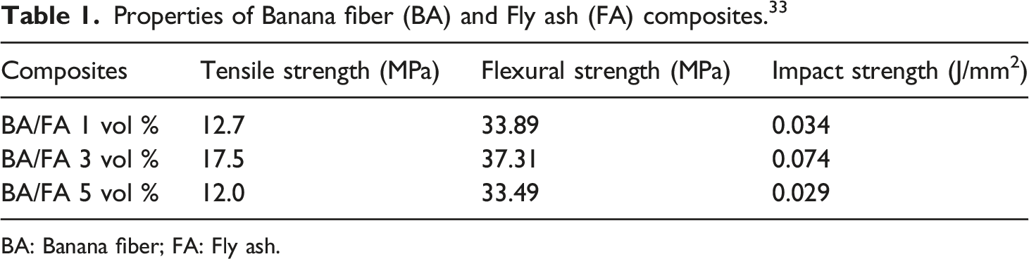
Banana fibers for use as reinforcement material were purchased from local sources in Gopichettipalayam, of Erode district in Tamil Nadu. Fly ash particles were obtained from Minelco International, Mylapore. Unsaturated polyester with catalyst was supplied by Sakthi fabric, Chennai. Hand layup technique was used to fabricate banana fiber polyester composites with fly ash filler. Unidirectional oriented 30 vol % banana fibers was used to fabricate three different composite materials by varying the volume percentage of fly ash as 1, 3 & 5%. Fly ash was mixed with the polyester matrix and then stirred for uniform distribution. Coupling agents like methyl ethyl ketone peroxide (MEKP) and cobalt octate each 1% as recommended by the supplier were added to the mixture and stirred again to attain a homogeneous state. The laminations of composites were fabricated by placing banana fibers in a sheet metal mould with 250 * 150 * 10 mm dimensions. The matrix mixture was poured over the layers of banana fibers and air bubbles removed with help of a roller. The molud was subjected to 25 kg on top in a closed condition for 24 h curing under room temperature. Fabrication of hybrid banana fiber composites is shown in Figure 1. Properties of fabricated composites are listed in Table 1. Fabrication of Banana fiber/fly ash composites. Properties of Banana fiber (BA) and Fly ash (FA) composites.
33
BA: Banana fiber; FA: Fly ash.
Drilling
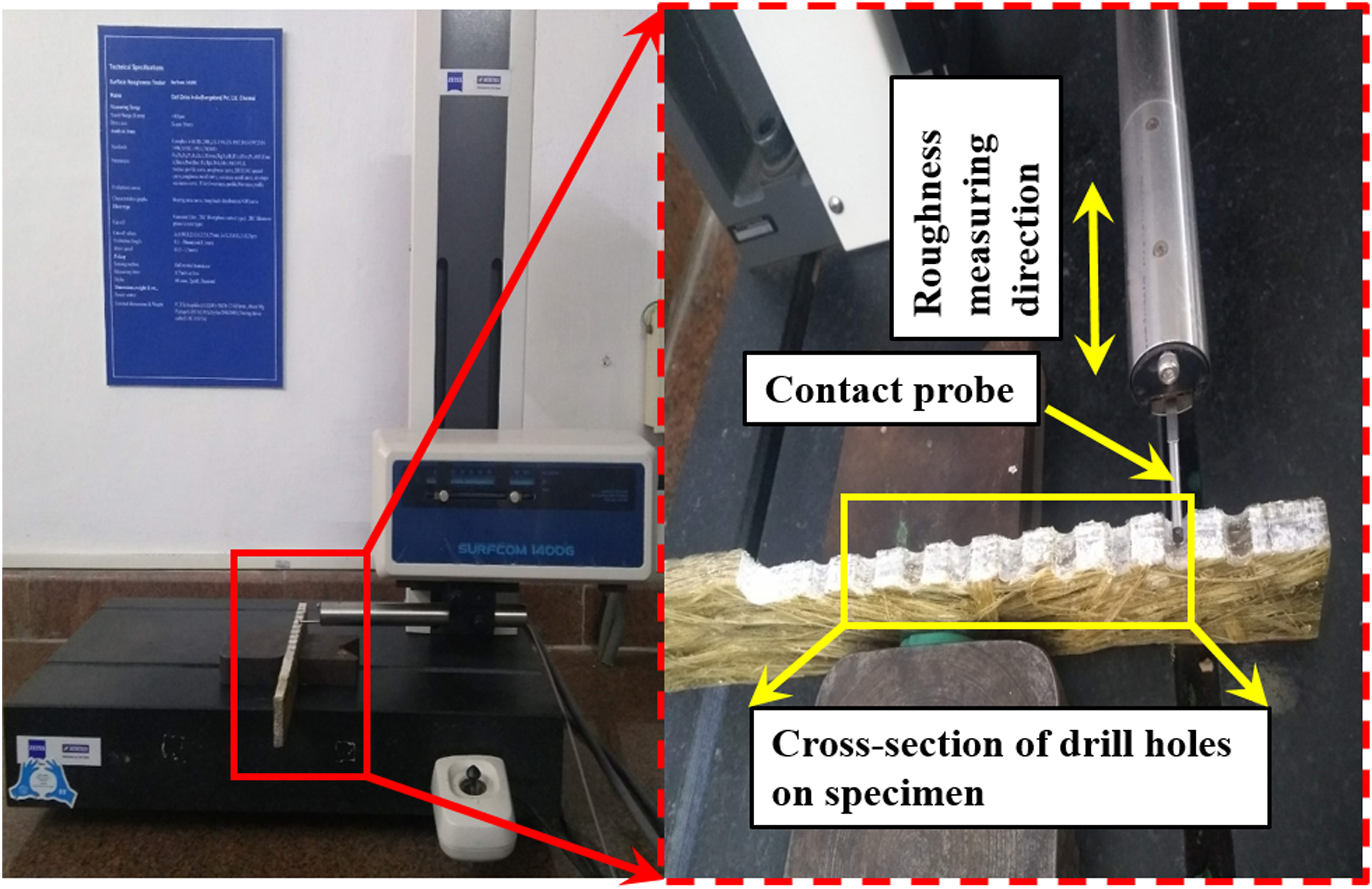
The specimens for drilling operation were prepared with 250 * 50 * 10 mm dimensions and subjected to drilling using a drilling machine (Specifications: three Axis VMC, Model- BMV 35 T12, CNC controller – Siemens- Sinumerik 828C Basic, spindle power of 3.7 kW and maximum drill speed of 8000 r/min) with a 6 mm HSS drill bit, a multi-component Dynamometer (9257, 10 kN) of KISTLER make. A top plate with 100 × 170 mm dimensions was used to record thrust force. The delamination factor and surface roughness were procured with the help of an OLM Vision Measuring System (OLM 3020) with magnification ranging between ×30 – 180X and a Surfcom 1400G (Carl Zeiss) having a measured length of 4 mm under speeds of 300 mm/s. The details are illustrated in Figures 2 and 3. Experimental Setup. Measurement of Surface Roughness.
Experimental plan

Process parameters and levels of the drilling study.

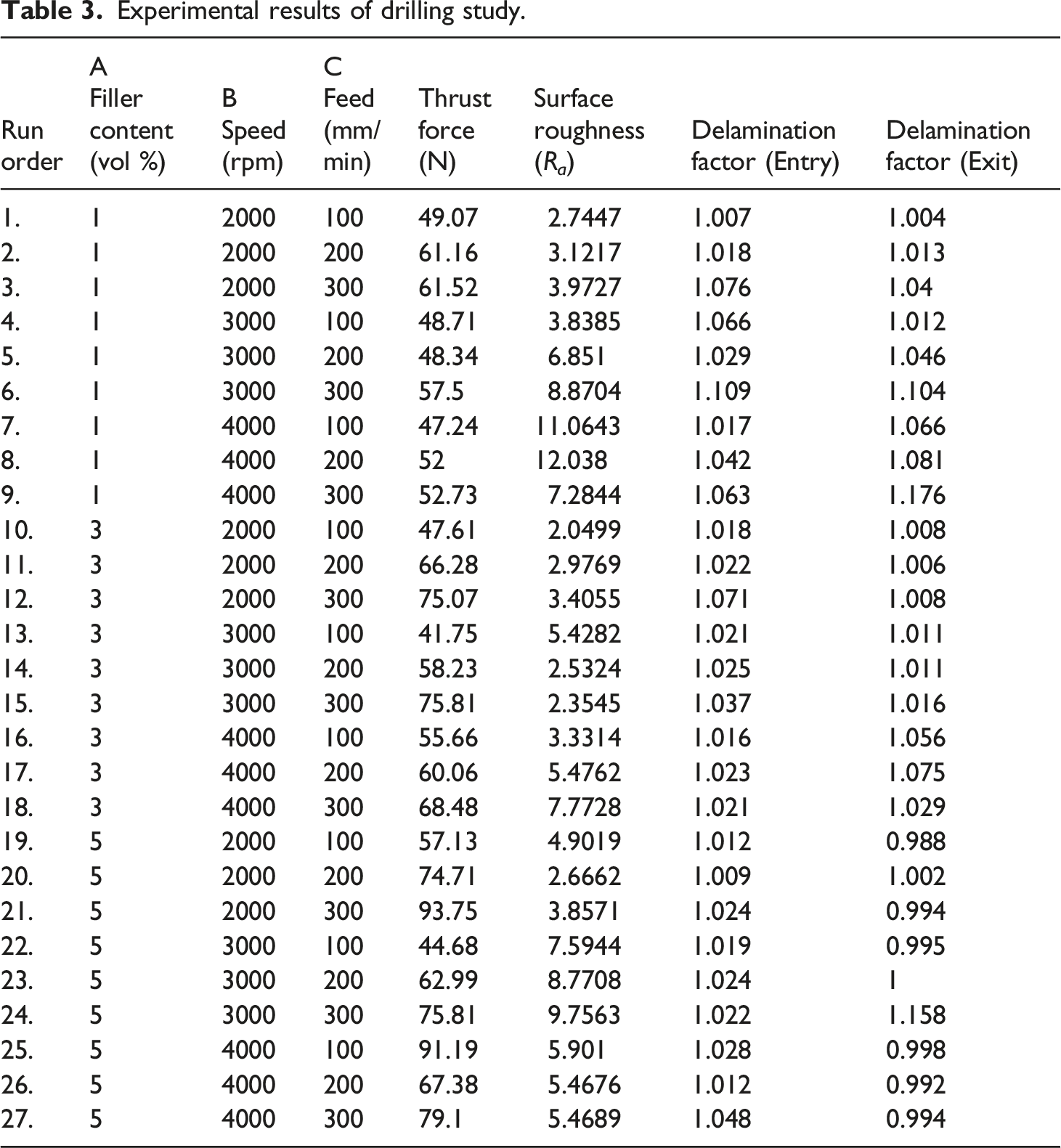
Experimental results of drilling study.
Response table for SN ratios.

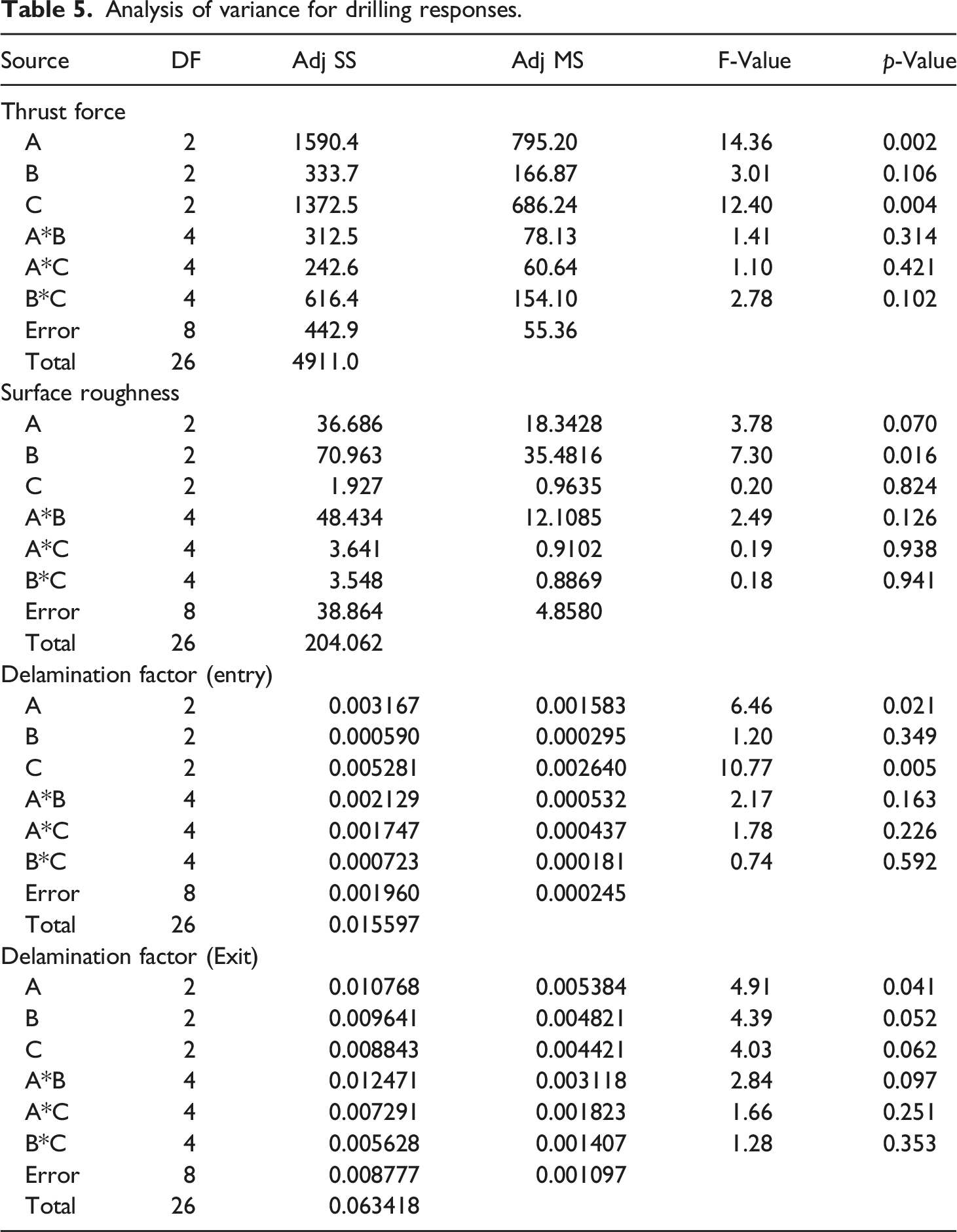
ANOVA provides the significance of each factor for all responses, it contains F-value, p-value and percentage of contribution. If F value is larger, then significance is higher.
The contribution of each factor to responses was calculated from equation (2) as follows:
Results and Discussion
Thrust force
Thrust force is an important response obtained during the machining of composite materials reinforced with fibers. The recorded thrust force for the present investigation is listed in Table 3. The study of the mechanism and generation of thrust force are necessary as they directly influence the quality of the drilled hole during the drilling of fiber-reinforced polymer composites. Thrust force is directly proportional to the resistance to feed and bending. An increase in feed rate results in enhanced thrust force. The influence of cutting parameters and the reinforcement on the thrust force is shown with corresponding SN ratios in Figure 4(a). On varying filler content, thrust force was maximum at filler content 5 vol%, followed by 3 vol% of filler content. Filler content with 1 vol% generated minimum thrust force. According to the SN ratio plot, increasing filler content and feed rate resulted in increased thrust force. The increment in thrust force was due to the high contact area generated between the cutting drill bit and the work material. Addition of hard fly ash fillers increased the hardness of the material with elevated resistance to the drill bit penetration which resulted in maximum thrust force. The generation of thrust force is related to material removal by the drill tooltip while penetration of the composite is in the form of chips. Addition of fly ash particles acts as solid lubricant additives which were stimulated by the temperature generated through friction between the drill bit and the work material.
31
It was observed that minimum thrust force was obtained under the following condition; factor A (1 vol %), factor B (3000 r/min), and factor C (100 mm/min). A softening effect was induced on the interfacial region through friction between the drill bit and work material due to higher operating speed. This resulted in an augmentation of temperature which lead to lesser force for penetration. Increasing feed rate resulted in increased thrust force due to resistance and elevated shear area.35,36 Drilling on flax fiber-reinforced polymer composites was experimentally investigated by Rezghi Maleki et al.
37
Maximum thrust force obtained was between 100 to 110 N which was higher than the maximum thrust force reported in the present investigation. This showed that the usage of fly ash as a secondary reinforcement in banana fiber composites lead to considerable energy saving with improved machinability. Mean of SN ratios for (a) Thrust force, (b) Surface roughness, (c) Delamination factor (entry) and (d) Delamination (exit).
Surface roughness
Surface roughness was the most promising response to ensure drilled hole quality. The effect of drilling parameters on surface roughness is shown in Figure 4(b) and Table 3. It was also reported that an increase in spindle speed and feed rate increased surface roughness. 38 The non-homogenous nature of the fiber-reinforced polymer composites greatly influenced surface integrity due to the matrix and reinforcement property. 39 From the SN ratio plot it was identified that varying filler content affected surface roughness which did not follow a specific trend like varying speed and feed. This was mainly due to the non-uniform distribution of fiber and filler in the polyester matrix. Minimum surface roughness was observed at the combination of factor A (3 vol %), factor B (2000 r/min), and factor C (100 mm/min). Maximum value of surface roughness was recorded with increased spindle speed. A higher spindle speeds resulted in fiber pullouts, delamination, and matrix surface cracks. These drilled hole damages were responsible for the rough improper surfaces which resulted in enhanced surface roughness. An increase in fly ash reinforcement resulted in a notable increment in surface roughness specially at lower feed rates. Higher loading around fibers contributed to its abrasive nature due to the formation of filler clusters. Poor surface roughness resulted in major problems like heat generation, and misalignment which subsequently increased the cost and production of the material. 40 The surface quality of the drilled hole was affected by parameters including drilling speed, feed rate, material drilled, and tool geometry. A good surface finish can be achieved by drilling at high spindle speeds and low feed rates.41,42 Higher thrust force resulted in rougher drill surfaces due to the fracture of composite lamina, debonding, and matrix cracks. 43
Delamination
Delamination is an important factor that influence the composite structure around the hole during drilling. This critical factor ensures the proper fitting of components during assembling. The present work analyses both the peel up and push out delamination factors for banana fiber reinforced polyester composites. The delamination factor has been extensively applied to investigate the level of damage at the entrance and exit of the drill on the composite material. Delamination factor (F
d
) is the ratio calculated from the maximum diameter (D
max
) of the delamination affected area to the drill diameter (D
0
) as shown in equation (3). 44,45
It can also be used as the ratio of delaminated area to the area of hole. After drilling, the specimens were analyzed for delamination damages around the holes by capturing images through machine vision on both the entry and exit sides. Generally, peel-up delamination occurs when the cutting edge of the drill bit reaches the top surface of the laminate. During drilling, separation of plies occurs through the flute of the drill bit at the top lamina of the laminate under cutting force. Push-out delamination occurs at the bottom of the drilled hole where the drill bit exits. During push-out delamination, the lamina under the drill bit experiences an axial compressive thrust. 46 Under this condition, the upper ply of the laminate pushes away from the adjacent lamina, and the interfacial bond breaks around the hole. Push-out delamination is the most critical factor contributing to service failure compared to peel-up delamination. Maximum delamination damages were identified in composites with 1 vol % fly ash compared to 3 & 5 vol % fly-ash added composites. It is also noted that maximum delamination for both hole entry and exit are recorded at high feed rate 300 mm/min. This can be detailed by the phenomena that using higher feed rate turned to obtain higher thrust force and thus results in larger delamination. 47
Figure 4(c) reveals the minimum peel-up delamination recorded with a combination of factor A (5 vol %), factor B (2000 r/min), and factor C (100 mm/min) respectively. Figure 4(d) shows that the minimum push-out delamination attained at A (5 vol %), B (2000 r/min), and C (100 mm/min) was similar to peel-up delamination. Typical delamination of drilled holes at entry and exit are shown in Figure 5. Sharp edges with few fibrils are identified at entry region of drilled hole and fiber pull outs/uncut fibers are observed at exit region of drilled hole. Typical delamination of drilled holes (a–c) peel-up delamination (entry) and (d–f) push-out delamination (exit).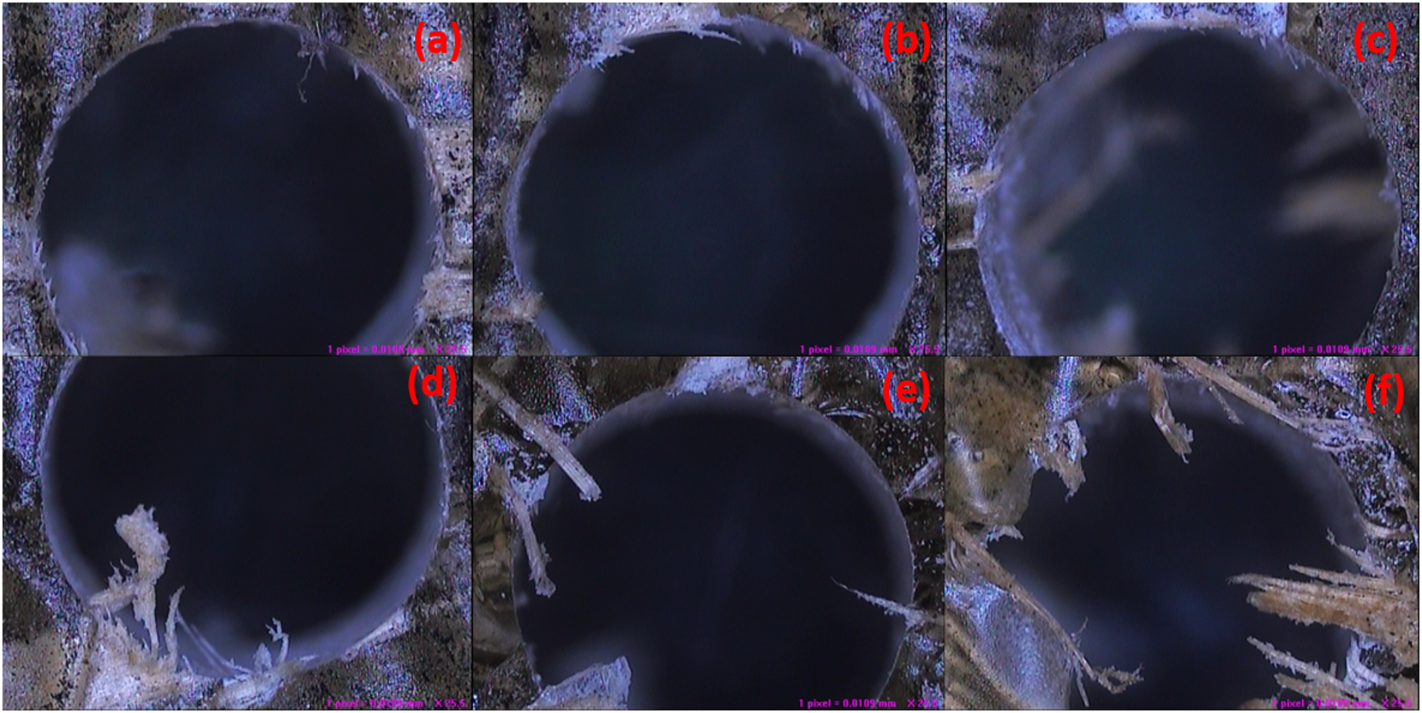
ANOVA analysis
Analysis of variance for drilling responses.
Contribution of process parameters
Figure 6(a) reveals the performance contribution of the control factors for thrust force which was highly influenced by factor A at 35.6% followed by factor C at 30.7% and factor B as 7.5%. The interaction effect of B*C was highly sensitive for thrust force by 13.8% followed by A*B at 7% and A*C at 5.4%. Figure 6(b) reveals the contribution of process parameters to surface roughness which was highly influenced by factor B (spindle speed) about 43% followed by factor A (filler content) of about 22.2%, and factor C (feed) having 1.2%. The combined effect of factors A*B was 29.3% which highly influenced surface roughness followed by factors A*C as 2.2% and factors B*C as 2.1%. Process parameter contribution to delamination entry is shown in Figure 6(c). Factor C with 38.7% was the highest contribution for peel-up delamination followed by factor A with 23.2% and factor B with 4.3%. The combined effect of A*B with 15.6% influenced entry delamination, followed by A*C with 12.8% and B*C with 5.3%. Figure 6(d) reveals the contribution of process parameters to push-out delamination. Factor A with 19.7% contributed to exit delamination, followed by factor B with 17.6% and factor C with 16.2%. The interaction effect of A*B with 22.8%, A*C with 13.3%, and B*C with 10.3% were the respective contributions to push-out delamination. Contribution of process parameters (a) thrust force, (b) surface roughness, (c) delamination entry & (d) delamination exit.
3D plot analysis
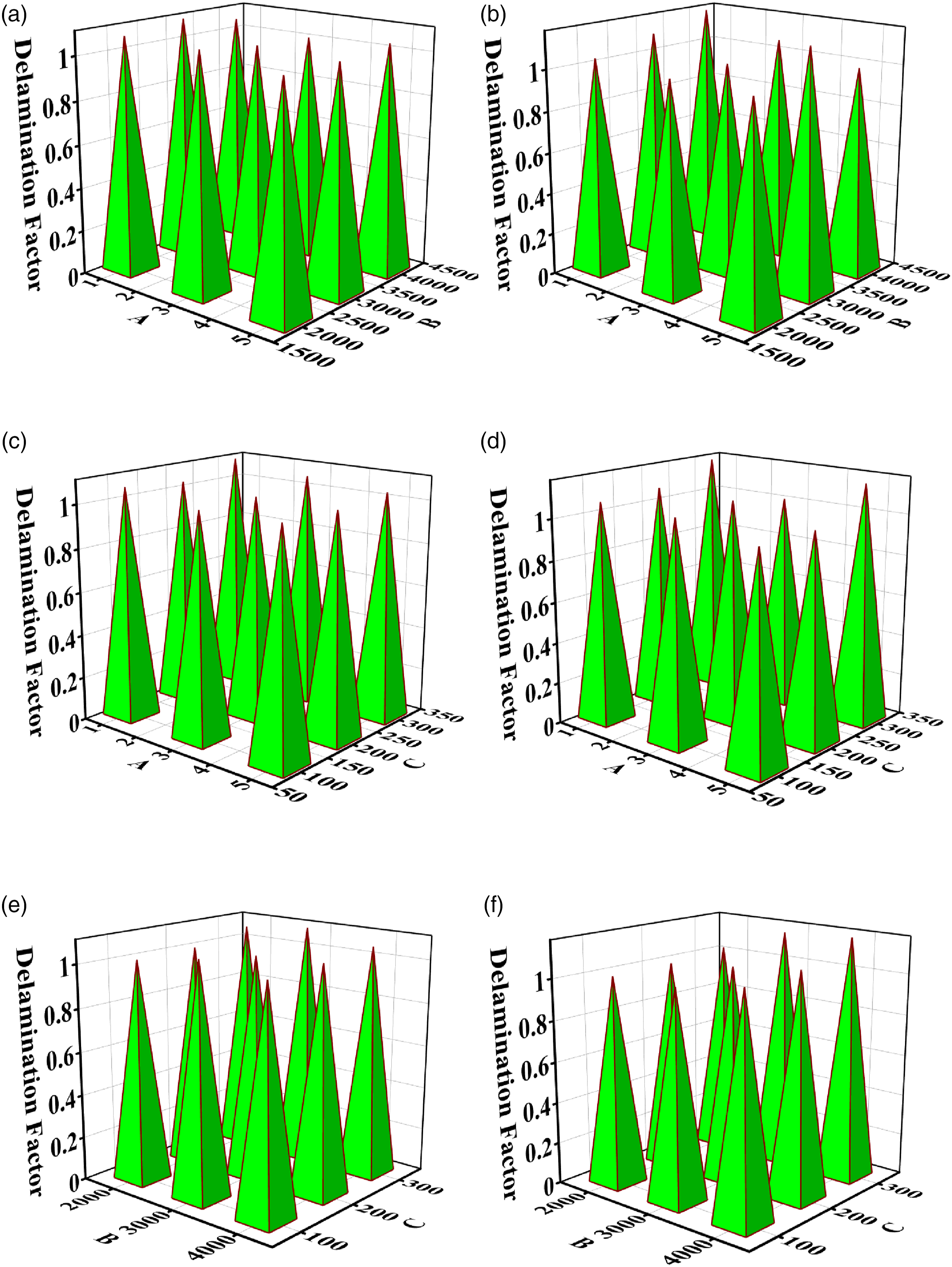
Figures 7 (a)–(f) show the combined effect plots for thrust force and surface roughness respectively. From the plot (Figure 7(a)), it was noticed that minimum thrust force was obtained by the combination of factor A (1 vol %) and factor B (4000 r/min). It also identified that increase in factor A was dominant compared to varying factor B results in high thrust force. Figure 7(b) follows a similar trend as factor A is dominant compared to factor C that affects thrust force while increasing. The interaction effect of factor B and C on thrust force is shown in Figure 7(c) where minimum thrust force was obtained at 3000 r/min and 100 mm/min. The combined effect of factors A and C on surface roughness is shown in Figure 7(d), where minimum surface roughness was achieved at 3 vol% and 200 mm/min. Figure 7(e) shows that minimum surface roughness was attained by a combination of factors A (3 vol %) and B (2000 r/min). The interaction plot for factors B and C is shown in Figure 7(f), where minimum surface roughness was recorded at 2000 r/min and 200 mm/min. In this interaction, factor B was highly dominant compared to factor C in influencing surface roughness. Figures 8 (a)–(f) show the interaction effect plots for delamination entry and delamination exit. During the interaction of factors A & B, minimum delamination occurred at factor A (5 vol %) and factor B (2000 r/min) for both entry and exit shown in Figures 8(a) and (d). Interaction effects of factors A & C (Figures 8(b) and (e)) provided minimum peel up and push-out delamination at A (5 vol %) and B (100 mm/min). The combined effect of factors B and C revealed optimum delamination at 4000 r/min and 100 mm/min for both entry and exit as shown in Figures 8(c) and (f). Similar observations of minimum delamination at lower feed rate and higher cutting speed reported by Gaitonde et al.
49
From the observation, the fact can be explained as the cutting speed increases the cutting edge cycle reduced at that region and elevation of temperature between cutting edge and composite surface soften the matrix phase and thus resulted in reduced damage. Increased damages are identified with increase in feed rate and increased area of cut results in high thrust force. 3D plot analysis (a-c) Thrust force and (d-f) Surface roughness. 3D plot analysis (a-c) delamination factor entry and (d-f) delamination factor exit.
Drilling surface investigation
Drilled hole surface damages occur in addition to the hole exit damages when drilling fiber-reinforced composites. Damages like fiber/matrix debonding, fractured fiber surface, matrix crack, fiber pullouts, rough debris, and debonding may occur due to different orientations by the laminae.50,51 Figures 9(a) and (b) show the different types of damages which occurred during the drilling of banana fiber/fly ash composites with a combination of factor A (1 vol %), factor B (4000 r/min), and factor C (300 mm/min). Feed was the most significant factor that influenced the drilled hole surfaces as per the previous discussion. At high feeds of 300 mm/min, the composites experienced fiber matrix damage due to banana fiber exposure, fiber pull-outs and fractured fibers at the drilled hole. Scanning electron microscope images of damaged holes at (a & b) 1 vol%, 4000 r/min & 300 mm/min. and (c & d) 3 vol%, 2000 r/min & 100 mmm/min.
Fiber matrix debonding, fiber-matrix defects, and uncut fiber pull-outs were observed at mid feed conditions. Matrix crack, fractured pull-outs, and fibrils from the rich matrix region were identified under the following conditions for factor A (3 vol %), factor B (2000 r/min) & factor C (100 mmm/min) as shown in Figures 9(c) and (d). Similar damages were observed by Yallew et al. 52 as the addition of fly ash helped to hold the banana fibers strongly during drilling with dimensional stability.
Exposure of peeled fibers, fiber/matrix debonding and fiber breakage perpendicular to the drill direction were identified under operating conditions with factor A (5 vol%), factor B (2000 r/min) & factor C (100 mm/min)as shown in Figure 10(a) and (b). Drilled hole damages influenced process parameters of the drill bit and drill material, types of matrix used, and heat generated during drilling. Though the material was banana fiber-reinforced composites, liquid coolant was avoided as moisture absorption problem would induce deterioration. However, the increased addition of fly ash resulted in agglomeration which was the reason for weak interfacial bonding, fractured fibers and filler/matrix sediments at pull-outs which were identified with the combination of factor A (5 vol%), factor B (2000 r/min), & factor C (300 mm/min) as shown in Figure 10(c) and (d). During drilling, the drill bit hit the upper ply and penetrated through the lamina resulting in significant heat generation which was transferred to fly ash fillers enabling them to function as solid lubricants. The combined influence of fly ash as a solid lubricant and the heat generated during drilling softened the polyester matrix resulting in minimized thrust force. Drilled hole surface damages can be reduced by the proper dispersion of filler material, providing suitable chemical treatment to natural fibers, and drilling at low feed rates. Scanning electron microscope images of the drilled hole at (a & b) 5 vol%, 2000 r/min & 100 mm/min, and (c & d) 5 vol%, 2000 r/min & 300 mm/min.
Conclusion
The present study was performed to analyse the drilling behaviour of banana fiber/fly ash reinforced polyester hybrid composites on varying filler content, spindle speed and feed rate. Thrust force, surface roughness, delamination entry and exit were evaluated using the Taguchi analysis. From the experimental study, the important outcomes are as follows: • An increase in feed rate increased thrust force. Filler content 1 vol % generated minimum thrust force. ANOVA results stated that the contributions affecting thrust force were shared by filler content (35.6%), feed (30.7%) and speed (7.3%) respectively. • Surface roughness was highly influenced by spindle speed (43%). Filler content 3 vol % revealed minimum surface roughness, while maximum surface roughness was identified at 1 vol %. • Minimum thrust force was observed under the following conditions: filler content (A) 1 vol %, speed (B) 3000 rpm, and feed (C) 100 mm/min. • Minimum surface roughness was recorded at a combination of factor A (3 vol %), factor B (2000 rpm), and factor C (100 mm/min). • Minimum delamination was observed with filler content (A) as, 5vol %, speed (B) 2000 rpm, and feed (C) 100 mm/min, for both peel-up and push-out.
From the outcomes, it can be stated that fly ash based natural fiber composites enhanced machinability performance which could increase opportunities for these composites being utilized in structural applications. This research opens the door to understand the machinability characteristics of filler based natural fiber composites.
Footnotes
Acknowledgements
We acknowledge with thanks to Centre for Composites and Advanced Materials, Machine Shop and Metrology Laboratory, Department of Mechanical Engineering, SRM Institute of Science and Technology, Kattankulathur for providing the research facilities. We acknowledge SRMIST for high resolution scanning electron microscope (HR-SEM) facility.
Declaration of conflicting interests
The author(s) declared no potential conflicts of interest with respect to the research, authorship, and/or publication of this article.
Funding
The author(s) received no financial support for the research, authorship, and/or publication of this article.