
Abstract
Al(OH)3 nanoparticles (ATH NPs) and phosphorylated cellulose nanofibrils (PCNFs) were used as user-friendly and comfortable coating components on flame-retardant fabric to improve its thermophysiological comfort and high-intensive heat protection properties. The effect of the PCNF imprinting and its attachment after the post-printing of a hydrophobic polyacrylate (AP) on the same (back side) or the other (front) side of the fabric, with and without the addition of ATH NPs, was considered, to maintain the front side (facing the wearer) as hydrophilic while keeping the back side (facing the outside) hydrophobic. The amount of coatings applied and their patterning were studied, varied with the ATH NPs’ concentration (1.7, 3.3 and 6.7 wt%) and screen mesh size used (60 and 135), based on the coating’ mass, fabric’s air permeability, thickness and microstructure. The reduced moisture build-up (55%), increased the water vapour (13%) and heat (12%) transfer from the skin, were assessed by applying PCNF under the AP, being more pronounced in the case of using a 135 mesh-sized screen, given the smaller, more densely distributed, thinner and imprinted pattern coatings. These effects were further improved by the addition of nanoporous ATH NPs, which allowed more homogeneous spreading of the moisture and its faster transport. Such a treatment also shifted the fabric’s degradation temperature towards higher values (up to 15°C), retained up to 30% of high-heat flux (21 kW/m2), prolonged the time to ignition by 11 s and reduced the total heat released by up to 60%, thereby providing better protection when exposed to the heat, due to the presence of the phosphorous (PCNF) promoted generation of an Al2O3 char acting as a barrier layer, while also reducing the production of heat and generation of smoke by 75%.
Keywords
Introduction
Thermal-resistant and flame-protective textiles represent a large area of applications, from firefighters, military and space personnel to industrial workers and foundries, whose flame-protective and physiologically comfortable properties depend not only on the fabric construction and fibre types’ combination (from very flammable cellulosic and common synthetic fibres to inherently flame-retardant filaments) but also from the type and concentration of flame retardants (FRs) used as a filament or coating additives by acting complementarily or synergistically. 1 A nanotechnology supported FR-protective coating 2 containing different nanoparticles (NPs), such as graphene, 3 carbon nanotubes, 4 titania 5 and zinc 6 oxides, with up to 10% of loading, applied as single- or multi-layer coatings with thicknesses up to few hundred μm, 7 are, thus, proposed to impart such multifunctional properties without compromising the inherent characteristics of the substrate (such as flexibility, rigidity and stiffness). Such coatings act as thermal insulators, absorbing the heat and oxygen from the atmosphere and blocking their transfer through the textile. In addition, they are entrapping the volatile species produced by the substrate (that can fuel the combustion further) and, hence, protect it with pyrolyse instead of burning. 2
As toxicological and ecological concerns, as well as fabric handling after use, are becoming new issues and challenges of EU Regulations and the forthcoming circular economy strategy, 8 nanosized inorganic minerals like aluminium trihydroxide (Al(OH)3, ATH) have been proposed as alternative environmentally friendly and inexpensive FRs, among others.2,8 ATH NPs decompose endothermically (1300 kJ/g) to Al2O3 in the range of 180–200°C with the elimination of water, 9 which dilutes combustible gases, reduces the burning temperature and prevents the access of oxygen by formation of a protective ceramic or vitreous layer on the surface, thus improving its thermal stability. 10 The effect is increased by decreasing particle sizes, 11 increasing concentration 9 and improved dispersibility, 12 which, however, might influence the fabric’s mechanical properties negatively. 13
However, there are only a few, recently published studies, aimed at modifying the textile substrates with ATH NPs. ATH NPs were applied on cotton fabric through epoxy resin by brush-coating, 14 through vinyl modification by the knife coating method, 15 or being immersed in an ATH/antimony pentoxide (Sb2O5) solution, 16 thus producing a superhydrophobic (contact angle up to 134°), self-cleaning and flame-protective fabric. In addition, the Mg/Al hydroxides were applied as double layered structures 17 and Al2O3 NPs in a multi-layer deposition. 18 The synergistic thermal effects of polyurethane, ATH NPs and triphenyl phosphate have also been shown when applied on a cotton/polyester fabric. 19 Good thermal insulation and flame resistance of polysulfonamide fabrics were obtained by electrostatic assembling of ATH NPs as a thin layer film on their surface, 10 or the sol–gel deposition method. 20 Boehmite (AlO(OH)), another form of ATH NPs, was also used to treat polyester and cotton fabrics, which increased their residues, slowed the degradation rates, suppressed the dripping effect and changed the degradation profile.8,21
Considerable research has also been performed recently on improving the moisture management properties of such textiles, that is, to improve (kinetically and quantitatively) the transfer of body moisture away from the skin to the outer surface of the fabric to evaporate and, thus, together with high thermal transfer and good air permeability, impact on the fabric’s thermophysiological comfort properties.22–25 Due to the low moisture absorbency of most FR synthetic fibres (as aramids and acrylates), the blends with cotton or FR viscose (containing FR phosphorous/sulphur additives) fibres, which possess high sorption properties, are, thus, proposed in the fabric construction to achieve sufficient functionality and moisture comfort. 2
In this work, ATH NPs are used in combination with phosphorylated cellulose nanofibrils (PCNFs) as user-friendly 26 and wear-related comfortable (moisture adsorbing 27 ) coatings on FR-protective fabric, 28 thus, to improve both its thermal and moisture comfort properties after a hydrophobic finishing. To date, the usage of nanocellulose in textile finishing has been demonstrated to improve mechanical29,30 and antibacterial 31 properties, electrical conductivity, 32 dyeing 33 and inkjet printing 34 efficacy and adhesive. 35 To the best of our knowledge, there is only one research available so far where phosphorylated cellulose nanocrystals were used as an FR additive in combination with chitosan to improve the thermal stability of the fabric. 26
For that purpose, PCNF was screen-printed on the fabric’s surface, followed by the printing of a hydrophobic polyacrylate (AP), using different openings of the screen and different printing strategies (i.e. to print PCNF on the same, or other side of the fabric as the AP), with or without different content of ATH NPs. The influence of the coatings’ mass and penetration on the fabric’s thickness, air permeability, water vapour and thermal-resistance (assessed at the skin temperature) was considered, besides the wetting properties, followed by thermogravimetric, flammability and combustion testing, as well as determining its mechanical and abrasion properties. In addition, in order to determine the coating efficacy on high-intensive heat transfer, the samples’ back sides were exposed directly to temperatures between 303 and 565°C, to mimic the environment under real and extreme conditions of use/wearing. 36
Experimental
Materials
Flame-retardant (FR) fabric of 145±1.4 g/m2 mass (ISO 3801), 0.332±0.02 mm thickness (ISO 5084:1996), 36 threads/cm in the warp direction and 51 threads/cm in the weft direction (EN 1049-2) was provided by Tekstina Ltd, Slovenia. The fabric was constructed as two-wefts woven fabrics (1/3 broken twill on the front side and 2/2 zigzag twill on the back side), made from spun yarns (a mixture of meta aramid and FR Lenzing viscose in the same 34/34% ratio) in both weft (which predominates on the back side of the fabric; that is, the face that looks outward while wearing) and warp directions, and viscous filaments (32%), which also appear in the weft direction, and predominate on the front side (i.e. the side that looks towards the wearer).
Water suspended phosphorylated cellulose nanofibrils (PCNFs) of 2–3 μm long and highly branched 10–200 nm wide fibrils with around 0.13 degree of substitution and zeta potential of around −45 mV at pH 10, as determined by conductometric titration, were provided by Xylocel Oy, Finland. All other chemicals used were purchased from Sigma-Aldrich (Germany) and used as received.
Preparation of aluminium trihydroxide nanoparticles
Water based aluminium trihydroxide (ATH; Al(OH)3) NPs were prepared from commercially available 16–21 μm sized Al(OH)3 flakes (Kemipal-W 900, Kemira KTM, Slovenia) by the two-stage grinding process using the grinding balls (Yttria-stabilized zirconia, Yotai Refractories Co. Ltd, Japan) with a diameter of 2 mm. Distilled water, Al(OH)3 flakes and polyethylene glycol (Mw of 400) as a dispersant were weighed into an agate grinding bowl from the Planetary Mill (Pulverisette 5 classic line, FRITSCH GmbH, Germany) in the mass ratio of 1: 1: 0.35, and ground for 60 min at 280 r/min. The grinding balls were then replaced with ones having a diameter of 0.5 mm, and 2-octanol (as an antifoaming agent) was added to grind the particles for another 60 min at 320 r/min. Dynamic Light Scattering (Horiba LB 550, Japan) and Brunauer–Emmett–Teller (BET) (Micrometrics Tristar 3000, Micromeritics, Norcross, GA, USA) analysis indicated that the ATH particles had an average size of 40 nm and specific surface area of 18.9 m2/g, while the pores’ diameter was in the mesopores range (14.9–15.9 nm).
Preparation of phosphorylated cellulose nanofibril-based dispersions and acrylate-based pastes
Both dispersions and pastes were evaluated for rotation viscosity at room temperature using a Haake rotational Viscotester V2 (Thermo Scientific, USA).
The 1.5 wt% PCNF dispersion (viscosity of 45±2 dPas) was used throughout the study. The PCNF dispersions were also prepared with the addition of 1.7 wt%, 3.3 wt% and 6.7 wt% of water pre-dispersed ATH NPs by mixing them for another 15 min with a rotary mixer, resulting in a viscosity of 50±2 dPas, 105±2 dPas and 115±2 dPas, respectively.
The acrylate paste (AP, pH of 8–8.5) consisting of 133.3 g/kg polyacrylate self-crosslinking binder (Tubifast AS 30), 1.67 g/kg ammonium water, 2.5 g/kg polymeric silicone as an antifoam (CHT entschaumer BSN), 20 g/kg melamine resin (Tubigat WAF 20), 18 g/kg ammonium salt of polymeric carboxylic acids as a thickener (Tubivis DRL 600), acrylic acid as a rheology additive (Tubigat R 130); all commercial products of CHT Bezema, Germany. Paste adjusted to the viscosity of 105±5 dPas by the addition of distilled water, was prepared by Tekstina Ltd (Slovenia). The APs of the same viscosities were also prepared with the addition of 1.7 wt%, 3.3 wt% and 6.7 wt% of water pre-dispersed ATH NPs by mixing them for another 15 min with a rotary mixer.
Both PCNF dispersions and AP pastes were designated according to the amount of ATH NPs added, where the number (1, 2 or 3) denotes the addition of ATH NPs (1–1.7 wt%, 2–3.3 wt% and 3–6.7 wt%, respectively).
Screen-printing procedures
The printing was performed on a Zimmer laboratory screen printing machine using a nickel-based rotary screen (SPG Prints B.V. Netherlands, formerly Stork) of different perforations (60 and 135 mesh size, 14 and 22% open area, 161 and 88 μm of holes’ diameter, 100 and 120 μm of screen plate thickness, respectively) and a steel-rod type squeegee of 15 mm in diameter, which pushed the printing dispersion/paste through the screen at a relevant pressure (magnet adjustable to no. 6) and rotating speed (manual setting, stage no. 5 ≈ 6 m/min).
The prints were performed as one or two-layer printings applied in two separate steps, as presented schematically in Scheme 1. In the case of two-layer printing, the PCNF-based dispersion (with/without the addition of ATH NPs) was printed first on the same, technical back side of the fabric (the side that looks outward while wearing) or other side (technical front side, the side that looks towards the wearer), followed by the printing of AP on the back side. In addition, the printing of AP (with/without the addition of ATH) on the back side of the fabric was performed in a one-layer process, acting as the reference. After each printing step, the fabrics were dried at 100°C for 3 min, using a laboratory heated air-circulation unit (Werner Mathis AG, Switzerland), and, finally, cured at a temperature of 170°C for 2 min to fix the AP coating using the same equipment unit. Schematic representation of the experimental procedures.
Fabrics’ washing and drying
The fabrics were laundry washed (1x) according to ISO 6330:2012 in a domestic washing machine (Gorenje SensorCare model W8665K, Slovenia) according to the MIX/Synthetic normal washing programme (at 60°C, and 1000 r/min) using IEC BASE A detergent (without bleaching agents; 66 g/2 kg), and dried at a low temperature (one dot) in a domestic drying machine (Gorenje SensorCare model D82426, Slovenia).
Fabrics’ testing and characterisation
All the fabrics were conditioned for 24 h at standard conditions according to ISO 139:2005 (temperature of 20±2°C and relative humidity of 65±5%) before the testing, or the tests were carried out under Standard conditions.
Scanning electron microscope imaging
Imaging of selected fabric surfaces were performed using a low vacuum (FEI Quanta 200 3D, Thermo Fisher Scientific Inc. USA) and Sirion 400NC (FEI, USA), equipped with an energy-dispersive X-ray spectroscope (EDX, INCA 350 (Oxford Instruments, UK), microscopes to evaluate the print’s structure, homogeneity/distribution, durability and elementary composition.
Mass change
The fabric mass was measured and the mass per unit area (g/m2) was calculated for each sample, and the mass changes (Δm) were assessed by using the following equation:
Thickness
Thickness was determined according to ISO 5084:1996 using a thickness gauge for Textiles and Rubber, Hildebrand, Germany.
Dimensional change
Dimensional change in both weft and warp directions was assessed according to ISO 5077:2007.
Air permeability
Air permeability through the samples was measured at a pressure difference of 100 Pa according to ISO 9237:1995, using a Karl Schroeder KG Air Permeability Tester D-6940, Germany).
Water absorption capacity
The samples (30 × 30 mm) were submerged in milliQ water for 60 s and then placed on a filter paper for 10 s for drainage and weighed. The percentage of water absorption was calculated using the following equation:
Hydrophilicity and absorbency
The fabric’s surface hydrophilicity and absorbency were assessed by measuring the fabric’s contact angle (CA) values (ASTM D5725-99) using a 3 mL drop of milliQ water (surface tension of 70 mN/m) on the Goniometer (OCA 35 model, Dataphysics, Germany), as well as the time of the milliQ drop staying on the fabric’s surface (before soaking into it). All measurements were conducted at room temperature and on both sides of the fabric. The results are given as the mean values of at least four measurements for each sample side.
Thermal and water vapour resistance
Thermal and water vapour resistance were assessed according to ISO 11092:2014 using the measuring instrument KES-F7 Thermo Labo II (Kato Tech Co-Ltd, Japan), where the heat flow was measured through the sample. The dry contact method was used for evaluation of the thermal resistance (which determines the dry heat flux across a given area in response to a steadily applied temperature gradient). The same procedure was used with wet filter paper on the heat plate for evaluating the water vapour resistance (which determines the latent evaporative heat flux across a given area in response to a steadily applied water vapour pressure gradient). Both parameters were calculated from the measured heat flow using the following equations:
High-intensity heat flow transmission
The high-intensity heat flow through the fabric was measured using a heat flow converter (type GTW-10-32-485A, Medtherm Corporation, USA). The fabric’s back side (10 × 10 cm) was exposed to the heat source (a heated conical beam) and the difference between the heat source and the value on the other side of the fabric was measured by a sensor covered with sapphire glass and placed 25 mm away from the heat source. The sensor and sapphire slide were held by calcium silicate plate holders with an area of 1 dm2 and thickness of 12 mm. The conical beam, with a heating coil temperature, was set to around 303°C, 415°C and 565°C, which corresponded to the heat flow of around 5 kW/m2, 10 kW/m2 and 21 kW/m2, respectively.
Thermo-gravimetric analysis and differential scanning calorimetry
TGA/DSC measurements of the fabrics were performed using a DSC1 analyser (Mettler Toledo, Switzerland), under an air atmosphere in a temperature range from 25 to 600°C and the heating rate of 10 °C/min, using a 50 mL/min flow rate.
Flammability testing
The flame-resistance of the front sides of the samples was evaluated according to ISO 15,025 by monitoring the ease of ignition of vertically oriented samples placed in a rectangular frame and exposed for 10 s in contact with a flame situated perpendicular to the sample surface in both warp and weft directions. If samples ignited the ignition time was recorded, and the mean values were determined of the ignition time of three tests.
Combustion testing
A combustion test was conducted using a conical calorimeter (Fire Testing Technology, UK) according to EN ISO 5660-1. Fabric samples (10 × 10 cm) were placed on a calcium silicate plate holder with an area of 1 dm2 and thickness of 12 mm and subjected to an irradiance level of 35 kW/m2, which heats the sample, and pyrolysis gases are emitted and ignited by a spark igniter. The emitted gases are collected in a hood above and transported through a ventilation system. The heat release was measured based on the measured oxygen concentration in the emitted smoke, where the smoke production was measured continually throughout the test with a laser system. An analysis gave the data of the time needed to ignition, the rate of heat released, the total heat released in a certain time period, the rate of smoke produced and the total smoke released in the time period.
Tensile and tear strength properties
Tensile strength and elongation (ISO 13,934-1) and tear strength (ISO 13,937-2) tests were carried out using a Tinius Olsen testing machine, H10KT (Tinius Olsen Ltd, Redhill, United Kingdom) with a 1 kN load cell. Five samples (250±2 mm × 50±1 mm) from both the warp and the weft directions of the preconditioned fabrics were taken randomly from the fabric for tensile testing, and then the maximum breaking force was detected for all samples, and, finally, the average values were calculated, expressed in N. In the case of tear strength testing, samples were first cut from the preconditioned fabric in both warp and weft directions, with dimensions of 200±2 mm × 50±1 mm. Then a longitudinal slit of 100±1 mm was made in the length, beginning from the centre of the width for all samples, and a mark of 25±1 mm from the uncut end of the strip, to indicate the position of the tear at the completion of the test. The average value of five tear peaks was detected electronically, expressed in N. The tear strength testing was performed at a gauge length of 200 mm, a constant rate of extension of 100 mm/min and preloading of 2N.
Abrasion resistance properties
The abrasion resistance of the fabrics’ front sides was evaluated according to ISO 12947-2 using a Martindale M235 Abrasion and Pilling Tester (SDL Atlas Textile Testing Solution, China), with a specimen diameter of 38 mm and a pressure of 12 kPa. The weight before and after specified cycles of abrasion was measured, and the weight loss was calculated and reported as a percentage of the weight before the abrasion (ISO 12947-3). The weight loss and cycles were determined at the tearing of a minimum of two threads, and at the breakdown. At least four measurements were performed for each selected sample to obtain statistically significant results.
Results and discussion
The coatings’ patterning and imprinting
The patterning and structuring of ATH NP-based PCNF dispersions and AP pastes on the fabric surfaces (both front and back sides) using different printing strategies (printed on the back side as one or two layers, or on both sides as one layer), and their imprinting, were studied by SEM imaging. The printing of both PCNF and AP, with or without added ATH NPs, resulted in a homogeneous and equally distributed deposition over the fabric surface, with no difference observed when using different (60 or 135) mesh sizes (except the size and thickness of the patterns). Only the fabrics printed with the 60 mesh screen and the highest ATH loading (in the AP or PCNF) are presented and discussed for that reason. As seen from Figure 1(a), the AP paste is equally distributed on the fabric surface in case of one-layer back-side printing, yarns appear smooth and regular, and some spots of AP are also observed on the unprinted/front side, indicating the possible imprinting of AP into the fabric’s empty structures and penetration through it. Indeed, the addition of ATH NPs did not change the AP patterns’ distribution and homogeneity, and their presence confirmed an efficient crosslinking within the polyacrylate. In addition, some ATH NPs could also be observed on the unprinted/front side of the fabric, reaffirming that some AP+ATH paste had also been pushed through the fabric on the other side. In the case of two-layer back-side printing (where the PCNF was applied as the first layer under the AP paste, Figure 1(b)) yarns look more glued together, but still seen clearly, while the presence of PCNF on the other/unprinted side cannot be visualised. However, the addition of ATH NPs into the PCNF resulted in fully covered yarns/threads, filled voids in between them and a rougher surface at the applied spots. A uniform spotted layering over the fabric surface can also be seen on the unprinted/front side, but with a smoother and in weft-direction covered pattern appearance. This indicates that such a coating has greater adhesion to the aramid/FR Lenzing viscose mixed yarns (predominant in the weft direction), while being very poor on the viscous filaments (appearing in the warp direction) as it looks almost uncovered. It can be also concluded that the efficiency of ATH NPs’ application in case of two-layer (PCNF+3ATH/AP) printing was higher than for the one-layer deposited AP paste containing ATH NPS (AP+3ATH), the crosslinking of which might not have been effective enough, and had, thus, been partly removed during washing. (a) Scanning electron microscope images of fabric printed on the back side as one- (AP, AP+3ATH) or (b) two-layers (PCNF/AP, PCNF+3ATH/AP), (c) or printed on both sides (front and back) as one-layer (PCNF-AP, PCNF+3ATH/AP, PCNF/3ATH+AP) and (d) with inserted EDX analysis (elemental composition) for selected samples taken at different parts. All the printings were performed with a 60 mesh screen size.
In the case of two-sided (back and front) printing (Figure 1(c)), the presence of solely PCNF and AP creates smooth surfaces, while rougher patterns were again obtained by the addition of ATH NPs, regardless of their addition within AP or PCNF. Slight spots of PCNF applied on the front side could also be observed, confirming its co-crosslinking by the AP applied on the back side and penetrating through the fabric. More densely structured patterns visible on the fabric’s front side in the case where ATH NPs were applied within the PCNF, rather than AP, indicate better dispersion and physical interaction between ATH NPs and PCNF than AP. In the latter case (application of ATH NPs within AP on the back side), the presence of ATH NPs was almost not observed (limited to individual points) on the other/front side of the fabric, which also indicates that PCNF limited the penetration of AP or ATH NPs containing AP coatings through the fabric.
Relatively uniform distribution of differently large aggregates of ATH NPs are seen on the SEM images of the printed samples presented in Figure 1(d), additionally confirming their integration and co-crosslinking within the AP (left image) or PCNF (right image), also being confirmed by the elemental compositions (the inserted Table in Figure 1) of patterns containing aluminium.
The effect of coatings on the fabric’s thickness, mass change, dimensional change and air permeability
The thickness, mass and dimensional change and air permeability of untreated and differently printed fabrics have been determined to assess the effect of the printing strategy, ATH NPs’ concentration and screen mesh size used on the printing`s efficacy. As seen from Figure 2(a), the printing of AP increased the thickness of the fabric by about 32% (to 439 μm using a 60 mesh-sized screen), and by about 22% (to 406 μm using a 135 mesh-sized screen), being related to the different AP depositions (14 g/m2 and 11.5 g/m2, respectively). However, surprisingly, the air permeability also increased slightly (by about 8.3%–973 l/m2s1/60 mesh and by about 4.4%–938 l/m2s1/135 mesh). The increased air permeability is related to the changed micropore composition in the form of irregular folds and bends of fibres, due to the elevated temperatures during drying and fixation. The additional effect was also caused by stirring in the washing and drying machine since non-treated fabric also possesses higher air permeability after being washed and dried. It is obvious that the deposition of AP was higher in the case of using a screen with larger (161 μm) holes’ diameters, although a lower (14%) open area and thinner (100 μm) screen plate. The addition of ATH NPs to the AP reduced the air permeability significantly (Figure 2(b)) (up to 45% to 697 l/m2s1/60 mesh and 511 l/m2s1/135 mesh at the highest ATH NPs’ concentration), which was further reduced (up to 48% to 717 l/m2s1/60 mesh and 49 l/m2s1/135 mesh) when PCNF was applied as the first printing layer, or the ATH NPs were applied by PCNF (up to 62% to 461 l/m2s1/60 mesh and 352 l/m2s1/135 mesh). However, the thickness of the fabric and mass change (Figure 2(b)) values were also reducing (by about 12.7%–383 μm/60 mesh and 23.4% to 311 μm/135 mesh) as compared to the sample printed only with the AP, which might indicate both the less effective crosslinking of AP in the presence of ATH NPs and its poorer adhesion with the fabric, thus resulting in partial removal during laundry washing, as already observed from the SEM images presented in Figure 1. This effect was even more pronounced by using a higher concentration of ATH NPs and a 135 mesh-sized screen with smaller (88 μm) holes, but more (22%) open area and a thicker (120 μm) screen plate. The effect of printing on the fabric’s (a) thickness and dimensional change and (b) air permeability and mass change values. The number (1, 2 or 3) before ATH denotes the addition of ATH NPs (1.7 wt%, 3.3 wt%, or 6.7 wt%).
An even more significant effect of air permeability reduction (up to 26.3%/60 mesh and 47.6%/135 mesh), accompanied with a slight increase of mass values (up to 14%, to 12–18 g/m2) and a decrease of thickness close to the non-treated sample (to about 397 μm/60 mesh or 296 μm/135 mesh), was obtained when the PCNF was applied as the first layer under the AP (in the case of two-layer printing), as compared to the AP-treated sample, being even more pronounced when ATH NPs were added to PCNF and using a 60 mesh screen (resulting in about 23 g/m2/60 mesh and 22 g/m2/135 mesh mass change, and up to 52.6%/60 mesh and 62.4%/135 mesh reduction of air permeability). The results indeed indicate that such a coating deposition is dependent primarily on the effectiveness of the AP crosslinking, its adhesion to the fabric and imprinting into it, and, secondarily, on the screen type used. Although the pre-coated PCNF (in the case of PCNF-AP) using 135 mesh size (with a more open area and thicker screen plate) might, thus, be better for the co-crosslinking with the subsequent AP deposition, it affected the AP crosslinking more, and its adhesion with the fabric, probably due to the hydrophilic nature of PCNF acting on the interface, and thus resulting in a lower mass change as compared to the samples printed with 80 mesh size or AP.
In the case of two-sided printing, where the PCNF was pre-printed on the other/front side of the fabric than the AP, the air permeability and mass change were comparable to that obtained by the one-sided two-layer printed sample (PCNF/AP), as it can be confirmed that the AP penetrated through the fabric and co-crosslinked with the PCNF pre-printed on the other side. This finding was further confirmed by the addition of ATH NPs to the PCNF, resulting in the highest mass change (about 24 g/m2) with comparable thickness (about 348 μm), but one of the lowest air permeabilities (reduced from 54% to 442 l/m2s1), due to the good adhesion of AP, its imprinting and crosslinking, which, altogether, resulted in a thicker and more compact coating, covering the surface tighter while filling the fabric`s internal microstructure, as confirmed by the SEM images (Figure 1), independent of the screen type used. On the contrary, mass change was again reduced (to about 18 g/m2) by adding ATH NPs in the AP, resulting in a comparatively lower air permeability (about 339 l/m2s1).
The above conclusions are also supported by the results of the fabric’s dimensional change (Figure 2(a)). While the non-treated sample did not shrink after being washed and dried, all other samples being printed with a 60 mesh-sized screen shrank in between 0.5 and 1.5% in the warp direction only, depending on the printing strategy, which, for samples printed using 135 mesh, was slightly lower and did not exceed 1%. The dimensional change was generally below 0.5% in the weft direction, due to the different prints’ deposition and imprinting, as well as the fabric`s construction. It is obvious that the type of woven structure plays an important role in the efficacy of printing, where the weft-directed threads (made of the blends of hydrophobic meta-aramid/acrylic fibres and FR viscose) are more exposed to the printing than the warp threads (also containing hydrophilic viscose fibres on the front side). Such a structure dictates not only the adhesion of prints to the fibres, but, above all, the AP mass change and its imprinting, which influence the threads’ reinforcement due to their crosslinking with AP and, consequently, the dimensional change of the fabric. This effect was more pronounced in the direction of more open/less dense (36 vs 51 threads/cm) warp-directed threads. The samples printed with pure AP on the back side (AP, PCNF/AP) using 60 mesh (given the highest mass change) thus showed the highest dimensional change (up to 1.5%) in the warp direction, being less pronounced when a 135 mesh size was used.
The effect of coatings on the fabric’s moisture comfort properties (water vapour resistance, surface wetting and water adsorption capacity)
Tests of the water vapour resistance, surface wettability and water absorption capacity of the fabric were performed to access the impact of different printing processes on the moisture management regime.
As seen from Figure 3(a), with the addition of ATH NPs into the AP, the water vapour resistance of the analysed samples declined up to 8.2% (to about 6.75 Pa m2/W in the case of the highest ATH NPs’ content) which was additionally reduced by using a 135 mesh (to about 6.28 Pa m2/W) giving about a 13.9% reduction, being accompanied by a 40–50% lowered water absorption capacity (to about 110%). By applying the PCNF under the AP or on the other side of the fabric in a two-layer printing, both the water vapour resistance and water absorbency were also reduced (up to about 6.5 Pa m2/W and 133%/60 mesh–123%/135 mesh, respectively), resulting in an additional decrease (up to about 6.20 Pa m2/W and 118%/60 mesh–101%/135 mesh) by inserting the highest concentration of ATH NPs, thus showing their synergistic activity. Such an increase of water vapour transmission through the fabric might be associated primarily with the nanoporous structure of ATH NPs, the finer capillaries of which in free-spaces allow more homogeneous spreading of water molecules and a higher flow speed, resulting in better moisture transport,
37
and, in addition, being regulated by the PCNF, resulting in different diffusion through the open spaces between the yarns and along the fibre itself, and their sorption-desorption (wetting) process, as already found in our previous study using microfibrillated cellulose.
28
The effect of printing on the fabric’s (a) water vapour resistance and water absorption capacities, determined on the front/F side, and (b) contact angle (CA) values and time of milliQ water drop staying on the fabric surface, measured on both the front/F and back/B sides. The number (1, 2 or 3) before ATH denotes the addition of ATH NPs (1.7 wt%, 3.3 wt%, or 6.7 wt%).
The wettability of the fabric was, thus, evaluated on both sides of the fabric surfaces by measuring the CA of the milliQ water drop in the moment of contact and the time it stayed. As can be seen from Figure 3(b), both sides of the non-treated fabric are fully hydrophilic; it was not possible to measure the CA values as the milliQ water droplet penetrated the fabric immediately. The printing of AP turned both fabric surfaces into entirely hydrophobic (CA ≥ 136°), confirming that the AP can spread and diffuse easily into the fabric and penetrate through it, thus covering both sides of the fabric, although the water drop penetrated faster on the front/un-printed side (in about 46 s/60 mesh and 27 s/135 mesh) as compared to the back/printed side (in about 161 s/60 mesh and 231 s/135 mesh). The addition of ATH NPs increased the CA value slightly on the back side (up to 139°/60 mesh and 160°/135 mesh), while reducing it on the front side (to about 129°/60 mesh and 121°/135 mesh). The time of the drop’s penetration was reduced on the fabric’s back side (to 51–73 s). The CA values on the front side of the fabric were additionally reduced in the case of two-layer printing using PCNF as the first layer, resulting in a hydrophilic surface (CA of about 107°/60 mesh and 65°/135 mesh), with much faster (a few seconds) drop penetration, being further reduced to about 36° when ATH NPs were added into the PCNF layer, and also accompanied by a slight reduction of CA on the fabric’s back/printed side. For two-sided printing, the hydrophobicity (CA was around 130°) of the fabric’s back side was not affected by the addition of ATH NPs by using different screen types, but it decreased with the printing of PCNF (to about 105°/60 mesh and 83°/135 mesh), and further with the printing of PCNF-ATH (to about 68°/60 mesh and 50°/135 mesh) on the other/front side turned it into hydrophilic.
In general, the thermophysiological comfort properties of the fabric are dependent mainly on fabric chemistry, thickness and porosity. On the contrary, nanocoating covers empty spaces on the fabric’s surface and thus reduces the air entrapped inside the fibres, which increases the thermal conductivity. 38 Both heat and water vapour transmissions are, thus, also correlated with the fabric’s air permeability. ZnO was applied by several authors37,38 where the water vapour resistance of cotton and polyester fabrics was reduced by more than 50%, where the deposition mass change varied between 115 and 238 g/m2, which is much higher than ours (10–25 g/m2) with comparable values of the fabric’s thickness. 38 Further, the water vapour resistance of cotton fabric declined by 37% when TiO2 was applied as a 120 g/m2 deposition that reduced air permeability even up to 87%, 39 being much higher than ours with about 62% reduction. The coating of polyacrylonitrile textiles using 10 wt% of SiO2 also lowered the water vapour resistance by about 85%, and additionally reduced the CA from 141° to almost 0°, meaning that the fabric permitted easy passage of water droplets due to its high affinity to water. 40
Superhydrophobic coatings have hardly been used because the moisture management properties of the fabric can be deteriorated significantly after the modification. In this regard, there have been rare studies41,42 that developed textile coatings which resulted in a material with asymmetric wettability, that is, one side of the fabric surface to be hydrophobic and the opposite surface to be hydrophilic. Kwon 42 fabricated a superhydrophobic lyocell fabric in which the CA exhibited greater than 161°, where the other side was superhydrophilic and able to absorb 117% of moisture. Those results came close to ours, where the fabric back side’s CA was around 121° (the highest 160°), and the front side as low as 36°, while absorbing around 118% of moisture.
The effect of coatings on the fabric’s thermophysiological comfort properties (thermal resistance and warm–cold feeling)
As seen from Figure 4, the warm–cold feeling values increased up to 15% for all the samples being printed with the highest amount of ATH NPs (to about 0.139 W/cm2/60 mesh and 0.156 W/cm2/135 mesh) on the same/back sides of the fabric, as compared to the non-treated one (to about 0.135 W/cm2), or only printed with AP (to about 0.126 W/cm2/60 mesh and 0.1156 W/cm2/135 mesh), while thermal resistance values decreased proportionately (to about 0.0596 m2K/W/60 mesh and 0.0525 m2K/W/135 mesh) towards a cooler feeling (values above 0.14 W/m2) denote the cold feeling sensation and higher heat transfer. On the other hand, samples without ATH NPs absorbed less heat and gave a warmer feeling. A slight lowering of the values of thermal resistance was obtained when the fabric was pre-printed with PCNF, being, however, more influenced when printed with the 135 mesh screen, due to a denser patterning and thicker deposition of components, as already confirmed by SEM imaging (Figure 1), as well as mass change (Figure 2(b)). In the case where the sample was printed with the two-sided process, the warm–cold feeling was further increased (to about 0.165 W/cm2) and thermal resistance lowered additionally (to about 0.0535 m2K/W), thus giving a 37% increase towards a cooler feeling, as compared to the only AP printed sample, independent of the mesh size used or by which printing (PCNF or AP) ATH NPs was applied. The results can be supported by the highest deposition and lowest thickness (Figure 2), influencing the fabric`s microporosity by imprinting into the structure, meaning that the air trapped inside the material is reduced and thermal resistivity lowered.
38
The synergistic effect of PCNF to ATH NPs can be supported by the fact that nanocellulose propagates thermal energy relatively better in combination with inorganic fillers and can lead to an even superior thermal conductivity.
43
The results coincided well with the other studies using nanoparticles, like ZnO and TiO2, where an increased thermal conductivity (20–26%) and absorptivity (17–23%) were obtained for cotton and polyester fabrics.38,39 The effect of fabric printing on thermal resistance and warm–cold feeling, conducted from the fabric’s front/F side (facing the wearer, i.e. being in contact with the skin) at 35±1°C.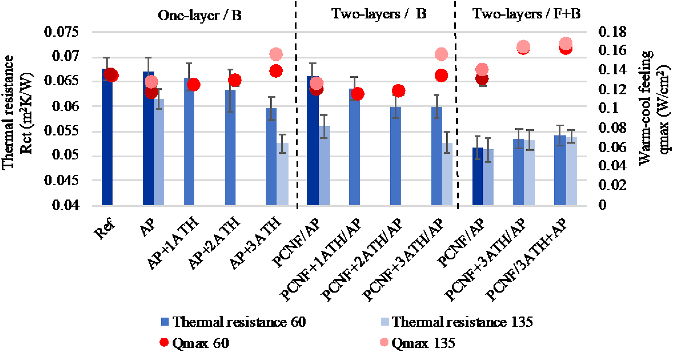
The effect of coatings on the fabric’s thermal properties
High-intensity heat transfer
Since the fabric consisted of meta-aramid, FR viscose and viscose fibres, it was assumed that its degradation behaviour would be in several steps, due to the combination of thermally differently stable fibres, which would also affect the transfer of highly intensive heat. In order to evaluate the thermal protective performance of different coatings, the heat transfer through the fabrics was, thus, considered, by exposing them to three different heat flow fluxes (5, 10 and 21 kW/m2, corresponding to heat of about 303°C, 415°C and 565°C, respectively) for 300 s, thus mimicking different environmental conditions during wearing, and to assess the effect of the coating on this type of protection. The radiation above 20 kW/m2 can cause life threatening burn injuries and a flashover immediately after exposure, while intensities up to 10 kW/m2 cause severe pain and scorching. 36
The effect of exposure duration and intensity of heat flow transmission through differently printed fabrics, exposed on the back side, is presented in Figure 5. The starting peak was a consequence of manual sample setting under the heat source. When the samples were exposed to a heat flow of 5 kW/m2 (303°C, Figure 5(a)), almost no changes between the samples’ curves are observed since all treated fabrics transmitted a heat flow in the range of 75.9%–76.8% (and non-treated about 73.4%), after 300 s of exposure without significant weight loss (0.4–3.4%). On the other hand, a heat flow of 10 kW/m2 (415°C, Figure 5(b)) changed the samples visually, which started to wrinkle and turned dark at the point being closer to the radiation, while weight losses increased to 19–24%, but samples transmitted different amounts of heat flow. The AP printed samples transmitted about 78.2% of the heat flow, which was the same when PCNF was applied as an under-layer, while it was reduced to about 72.3% when PCNF was printed on the other/front side of the fabric, meaning that the PCNF may have blocked approx. 7.6% more heat. Such an effect of PCNF could be the consequence of the free and better available phosphor groups present on CNF, that can trigger and promote the char formation on the fabric’s surface2,44 (Figure 5(d) – inserted SEM images showing a melted and glued coating with a rougher surface structure) which provides the heat barrier. The addition of ATH NPs to the AP lowered the transmitted flow only by about 2.8%, while it decreased by 11.4% and 10% when the ATH NPs were printed together with PCNF in a two-layer and two-sided process, respectively, probably due to a higher deposition expressed by thickness and mass change (Figure 2). None of the samples burned when being exposed to the heat flux of 21 kW/m2 (565°C, Figure 5(c)), but a considerable amount of smoke was observed for all the samples immediately after the exposure, corresponding to the pyrolyse products and combustion gases of some fibres and coating materials.
2
However, although the weight losses for all samples were in the range of 54–59%, all the samples still retained around 30% of the heat flux, showing no significant difference from those obtained at 10 kW/m2. The least heat was transmitted by samples coated on the same (back) side with PCNF-ATH NPs in a two-layered process, giving between 67.4%/60 mesh and 70.1%/135 mesh heat transmission (meaning up to 12% less heat transmitted compared to the AP printed sample, or up to 4.3% compared to the non-treated one), followed by the sample printed in the same way, but both-sided (of about 72.9%), which might be related to the smaller amount of its application at the latter. Approximately 67.4% transmittance means that only 14.1 kW/m2 of starting 21 kW/m2 was transmitted through the fabric to the skin, which would prolong the time before severe or life threatening burns occur. When comparing the results of the first few seconds, it is seen that all treated samples had the lower heat transmission than the non-treated one, meaning that, for about 25 s, the protection was higher by more than 10%. In further exposure, up to 100 s, all the samples transmitted around 74–75% of heat, except the PCNF+3ATH/AP coated sample, which gave significantly lower values for both mesh size screens. However, the sample printed with 135 mesh size showed better protection in the first 75 s, and then reached the constant around 70.1% of transmission, while the samples printed with 60 mesh size gave higher transmission at the beginning, which started to decrease after 50 s until reaching 67.4% at 300 s. The effect of printing on the heat flow transfer through the fabrics exposed with the back/B sides (facing the outside) to heat intensities of (a) 5 kW/m2 (around 303°C), (b) 10 kW/m2 (around 415°C) and (c) 21 kW/m2 (around 565°C), for 300 s at a distance of 2.5 mm with corresponding weight losses, and (d) SEM images of selected samples (AP+3ATH and PCNF+3ATH/AP) after exposure to a heat flow of 21 kW/m2.
It is obvious that synergistic effects between ATH NPs and PCNF are crucial for reducing the heat transfer and prolonging the time needed to reach this value since both PCNF or ATH applied alone gave higher heat flow transmittances (of about 74.9% and 74.2%). This can be related to the fact that some amount of energy was consumed by ATH NPs, which decomposed endothermically while generating an Al2O3 char acting as a barrier layer. 9 The presence of phosphorous promotes the charring 44 (Figure 5(d), SEM images), yield intumescence and inhibits the flame, which reduces the production of heat. 45 In addition, better dispersion of ATH NPs in the anionic and highly hydrophilic PCNF (Figure 1), as well as the higher mass change of fabrics printed (Figure 2(b)), compared to the synthetic acrylate-based paste, can contribute to such results.
Thermal stability
To identify the effect of differently printed fabrics on thermal degradation behaviour and corresponding enthalpy changes, the TGA and DSC measurements were conducted for PCNF+3ATH/AP printed with both (60 and 135) mesh-sized screens, showing the lowest heat transmission, and compared to the non-treated sample. As can be seen from Figure 6(a), the degradation of all samples followed a similar trend, showing three main weight loss stages. The first mass loss (of about 5%) appeared between 40°C and 120°C, attributed to the evaporation of the absorbed water. The 38% weight loss in the range of 230°C–310°C was rapid and corresponded to the degradation of the viscose,45,46 being also observed as the first broad exothermic peak on the DSC thermogram (Figure 6(b)). The following step started at around 375°C and belonged to the melting temperature of the meta-aramid, with the degradation temperature around 500°C,
47
where around 20% weight was lost. From 500°C, the mass loss was rapid, corresponding to the final decomposition of the viscose, FR viscose and meta-aramid, given the sharp exothermic peak, representing about 95% mass loss up to 600°C and leave almost no residue at the final 800°C. For the samples coated with ATH NPs and PCNF, no differences can be observed up to 240°C, but, when the viscose started to degrade, the degradation temperatures were shifted slightly to higher temperatures, showing the biggest difference in the range of 260–290°C, where the non-treated sample lost about 25% of mass at 265°C, the AP treated at 273°C, the PCNF/AP at 276°C and the ATH+PCNF/AP treated at 285°C, almost independent of the mesh size used (±3°C). Such a 15°C shift to a higher temperature was also observed on the DSC thermogram by the main exothermic peaks. Around 15°C higher degradation temperatures were also achieved by the ATH thin films assembled on polysulfonamide fabrics.
10
On the other hand, the degradation temperature of the jute fabric treated with different fractions of phosphorylated nanocellulose and chitosan was lowered by 27°C.
26
The effect of printing on the fabric’s (a) thermogravimetric and (b) differential scanning calorimetry analysis.
Flammability and combustion
The effect of printing on the fabric’s flammability and time to ignition (left) and flammability testing (photos) of two-sided printed fabric (PCNF+3ATH/AP).

Cone calorimetry combustion testing of the above selected samples was also performed at 35 kW/m2 (exposed at the back side) to mimic the first stages of developing fire, corresponding to the critical radiant flux required to ignite many combustible organic materials.
48
As seen from the graphs in Figure 7(a), the heat release rates (HRRs) of the samples printed with PCNF+3ATH NPs were decreased significantly, while the non-treated sample reached the HRR peak at about 46.2 kW/m2 in 15 s. The times for the AP coated samples were prolonged to 30 s and 40 s, and the peaks increased to about 7.5 kW/m2 and 53.6 kW/m2, using 60 and 135 mesh size, respectively. The PCNF/AP printed sample got a significantly lowered HRR, where, in comparison to the reference sample, no main peak was observed, but there was almost constant heat release in the first 40 s at 35 kW/m2. The presence of phosphorous in PCNF helps inhibit the flame and reduces the heat release, due to the reduced rates of heat release and mass loss during exposure.
45
For the PCNF-3ATH pre-printed sample, the heat release in the first 50 s was barely present, meaning that heat was released slowly and more constantly, pointing out the synergistic effects of PCNF and ATH NPs. The time to the peak HRR was significantly longer, 75 s and 110 s, and the peak reduced to about 8.8 kW/m2/60 mesh and 12.1 kW/m2/135 mesh. Additionally, the total heat release (THR, Figure 7(b)) of these two samples (PCNF+3ATH/AP) was also reduced by about 60%/60 mesh and 39%/135 mesh compared to the AP printed references, being comparable to the other studies using AlO(OH).15,21 The smoke production evaluation is also presented in Figures 7(c) and (d). The non-treated sample and PCNF treated one had very rapid smoke release, presented with a sharp thin peak, meaning that most of the smoke was produced and released in the first 25 s or 40 s, respectively. On the other hand, the samples printed with AP or pre-printed with PCNF+3ATH released smoke at slower rates (up to 40 s, or until 80 s/60 mesh and 100 s/135 mesh), before reaching the constant and higher amount of smoke released (up to 66.9 m2/m2/60 mesh and 72.1 m2/m2/135 mesh), meaning twice as high an amount compared to the AP-treated samples (31–35 m2/m2), due to the presence of PCNF. However, the time to ignition (TTI; Table 1) was prolonged from about 10 s for non-treated and 8 s for PCNF treated to about 23 s/60 mesh and 38 s/135 mesh for AP printed samples, and then lowered again to about 10 s/60 mesh and 21 s/135 mesh for samples printed with PCNF/ATH NPs. Anyway, the PCNF+3ATH/AP sample printed with 135 sized mesh still needed about 11 s longer to ignite, compared to the non-treated one, being comparable to the reference study, where only AlO(OH) was used.
15
The effect of printing on the fabric’s cone calorimetry analysis during exposure on the back/B side to 35 kW/m2: (a) heat release rate, (b) total heat release, (c) smoke production rate and (d) total smoke release.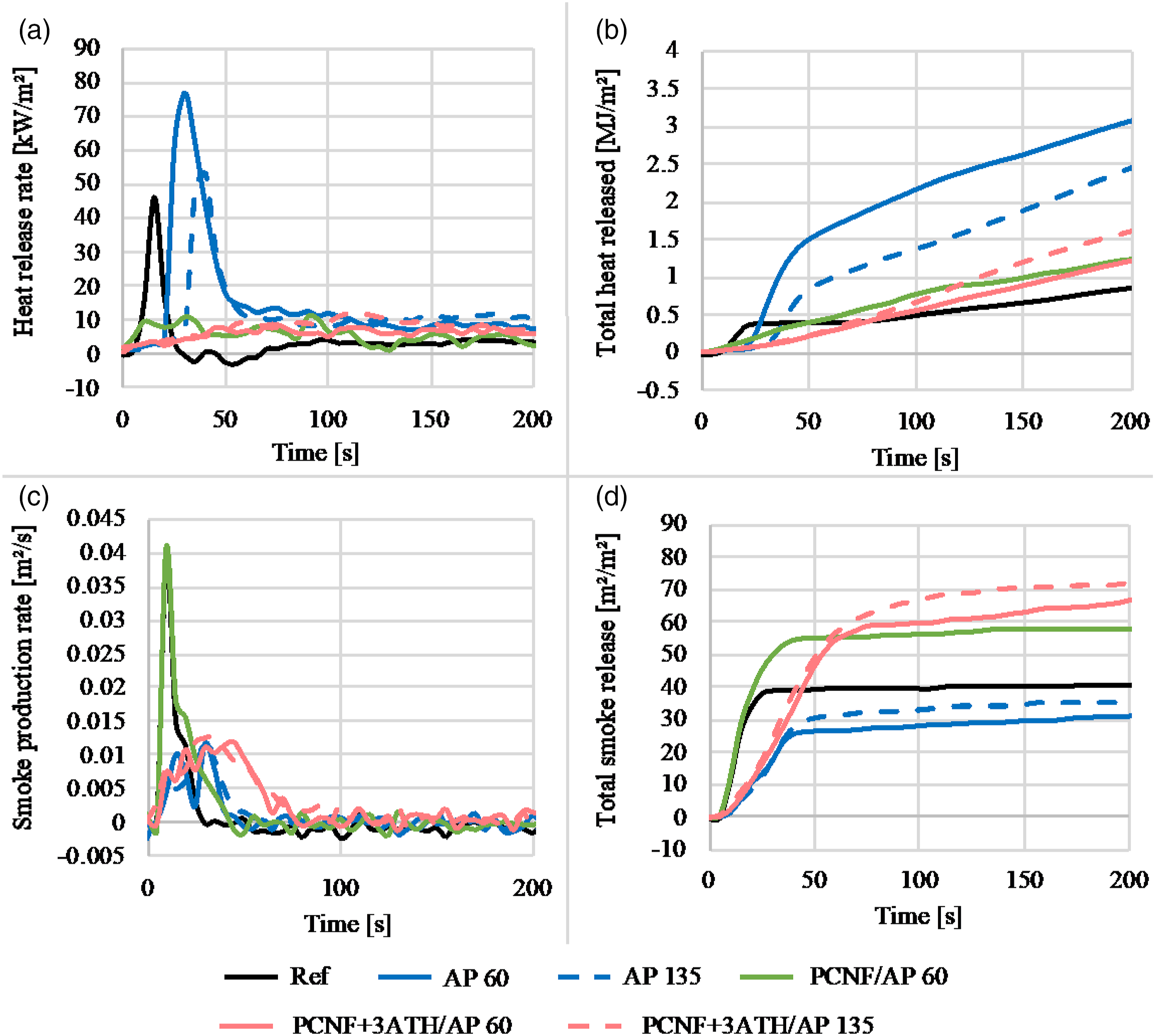
The effect of coatings on the fabric’s tensile and tear strengths and breaking elongation properties
As shown in Figure 8(a) and (b), the reference fabric had higher tensile strength in the warp direction in comparison with the weft direction, due to both the fabric`s construction and its chemical composition, namely, two-wefts and more dense (51 threads/cm) system made from a mixture of meta aramid, FR Lenzing viscose and viscous filaments, compared to the warp (36 threads/cm) made only from meta aramid and FR Lenzing viscose. The results also show that printing of AP improves the fabric’s tensile strength in both directions, up to around 5.3% (about 603 N) in the warp and 9.8% (about 490 N) in the weft using a 135 size mesh. A pre-printing of PCNF gives an additional effect (up to 12.6%/641 N in the warp and 18–21%/541 N in the weft), independent of the side of its application (on the back or front side), as well as the type of screen used, which was in good agreement with the mass and dimensional changes in the warp direction as discussed previously (Figure 2). The addition of ATH NPs to AP reduced the tensile strength in both directions (to about 550 N/warp and 467 N/weft) with the increasing of NPs’ content, which was much less when NPs were added to the PCNF (resulting in about 600 N/warp and 452 N/weft), and insignificant when PCNF was pre-printed on the other side (resulting in about 614 N/warp and 467 N/weft), independent of the mesh size used. The elongation values followed a similar, but much less pronounced trend in both directions. When compared to other related studies, using ATH NPs for textile treatment, the tensile strengths are often deteriorated by between 3 and 18%, dependent on the ATH concentration applied (10-60 wt%), the type of fibres used (natural vs synthetic) and the structure of the fabric.10,14,19 An (up to 76%) improved tensile strength of the fabric was shown when Mg-Al-layered double hydroxides had been embedded into the coated polymer matrix,
17
or the Al2O3 was coated (up to 10%) by a multilayer coating.
18
The effect of printing on the fabric’s tensile and tear strengths and breaking elongation measured in the warp and weft directions.
On the other hand, due to the fabric`s two-wefts construction, it showed lower tear strength of the warp threads (about 13.5 N) in comparison with the weft threads (about 26 N); that is, the lower density of the warp threads offered lower resistance against tear propagation. However, an obvious improvement (up to 38.5%) of warp tear force and slight reduction (to about 11%) of weft tear force can be noticed when the AP was printed to the fabric`s back side. On the other hand, while similar warp tear strength values were detected when the PCNF was pre-printed, independent of the printing strategy and that the highest content of ATH NPs were used, the weft tear strength was reduced even up to 30–60% as compared to the AP only printed fabric. Such properties might be related to the fabric`s structure, which allows the weft threads (which predominate) to move apart from each other because of the imprinted AP/PCNF (as seen from the SEM images, Figure 1), thus giving lower resistance to tear propagation. Besides, reduced tear and tensile strengths at rupture are common when ATH NPs are applied to the fabric since NPs form irregular regions and cracks in the matrix, thus making it more susceptible to destruction. 19
The effect of coatings on the fabric’s abrasion resistance
The abrasion resistance properties of differently treated fabrics have been studied on the front side of the fabric, which would be in contact with the skin during wearing. The weight loss and cycles were determined at the tearing of a minimum of two threads and at the breakdown. As seen from the results presented in Figure 9(a), already the AP printed on the back side improved the fabric’s abrasion resistance compared to the non-treated one, by a gradual increase of its mass loss percentage, resulting in a resistance from about 55,000 up to 76,000 cycles using a 135 size mesh. The pre-printing of PCNF additionally improved the breakage to about 80,000 cycles, while two-sided printing gave the best abrasion results, since the breakage occurred at about 86,000 cycles, which might be due to a better connection between the fibres (SEM, Figure 1), causing better resistance to higher and long-term applied stress. On the other hand, the addition of ATH NPs to AP or PCNF had the opposite effect, independent of the printing methods since the breakage already occurred between 45,000 and 50,000 cycles. The same trend followed the colour loss (Figure 9(b)) and starting point when damages occurred (Figure 9(c)), which was improved greatly by applying the PCNF (from 60,000 cycles/AP to 70,000 cycles/two-layer printing up to 80,000 cycles/two-sided), and it reduced with the addition of ATH NPs. Due to the lower resistance of abrasion, the mass loss of samples treated with ATH (Figure 9(d)) was also higher by about 5% than the other samples, meaning that the presence of ATH NPs weakened the connections between fibres, being also reflected in the lowered tensile and tear strengths. The effect of printing on the fabric’s (a) abrasion cycles at breakage, (b) abrasion cycles at colour loss, (c) abrasion cycles at start of damage and (d) weight loss at breakage. Sample coding: One-layer printed on the back side (1: Ref, 2: A and 3: AP+3ATH), two-layers printed on the back side (4: PCNF/AP and 5: PCNF+3ATH/AP), both-sided one-layer printing (6: PCNF/AP, 7: PCNF+3ATH/AP and 8: PCNF/3ATH+AP).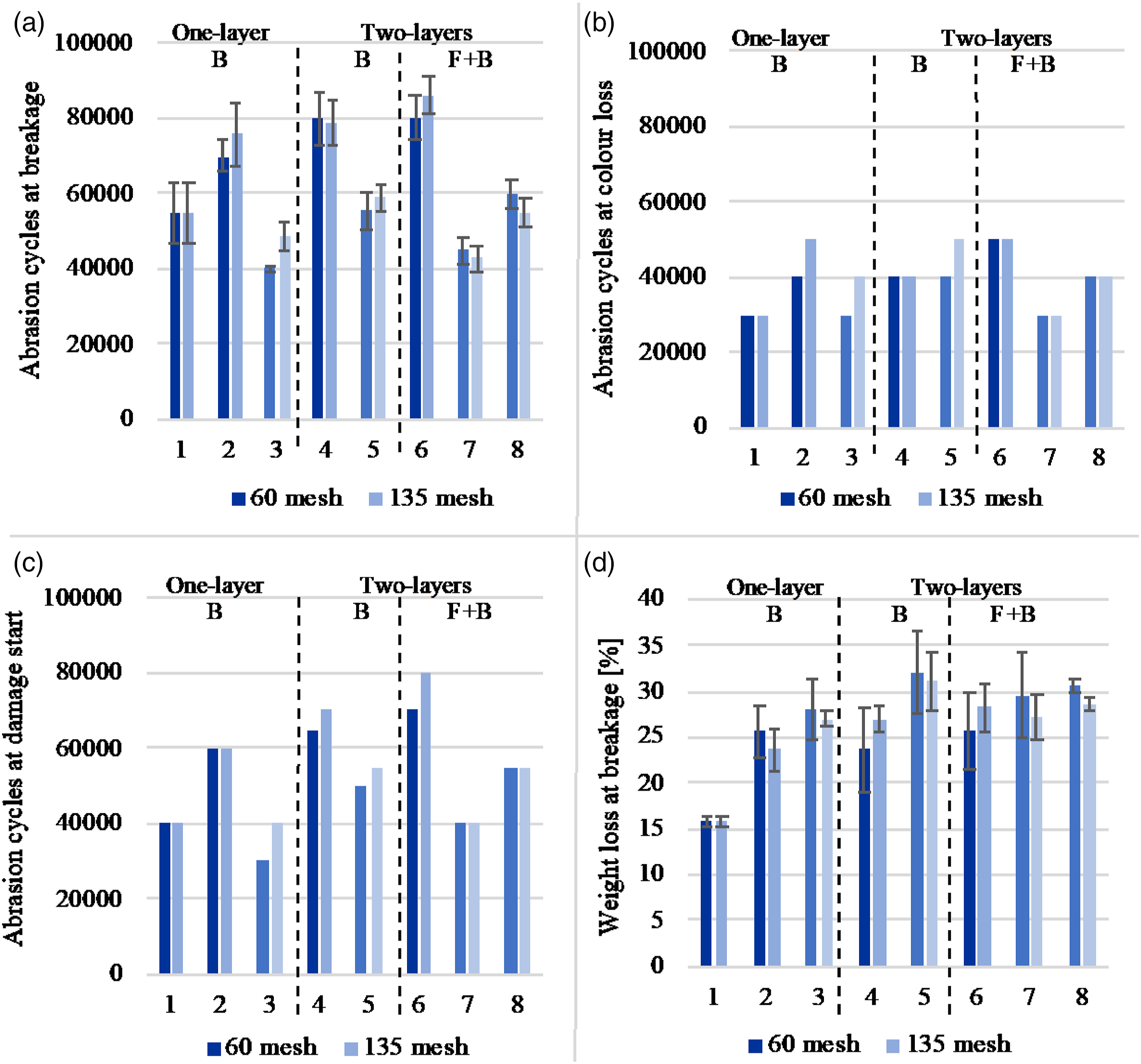
Conclusion
Flame-retardant fabric was screen-printed with phosphorylated cellulose nanofibrils (PCNFs), followed by a hydrophobic polyacrylate, with and without the addition of aluminium trihydroxide (ATH) nanoparticles (NPs), using screens of different mesh sizes and different printing strategies (i.e. printing of PCNF on the same or other side of the fabric as the polyacrylate), to improve the thermophysiological comfort properties of the fabric and thermal stability when exposed to high-intensity heat.
The results indicated that the fabric properties were influenced primarily by the coatings’ quantity (mass change) and their imprinting into the fabric (influenced by the screen mesh size and by the way the ATH NPs were applied, i.e. with polyacrylate or PCNF) and secondarily by the way the PCNF was pre-printed, regulating the spreading of moisture, its uptake kinetics and transfer. The PCNF maintained one side of the fabric as hydrophilic, while improving its surface wetting (moisture uptake kinetics), as well as tensile and tear strength, and abrasion resistance. The nanoporous ATH NPs, in addition, lowered the water vapour and thermal resistance, resulting in its better transfer while under excessive heat away from the body through the fabric, contributing to a better experience when worn. Through their synergistic interaction, endothermal decomposition of ATH NPs and better thermal and oxygen conductive PCNF also improved the heat protective properties of the fabric significantly, by generating an Al2O3 char acting as a barrier layer, wherein the phosphorus-modified CNF, in addition, promoted the charring. This retained up to 10% more (total about 30%) of the applied heat flux (21 kW/m2) than the untreated sample and resulted in an increased degradation temperature, lower heat and smoke release rate and prolonged the time to ignition.
This work demonstrates the significant potential of using mineral NPs together with nanocellulose as an efficient non-toxic, low-cost, environmentally benign, as well as user-friendly and wear-related comfortable alternative to conventional textile finishing. Such a finishing process would also be relevant to other personal-protection applications requiring a water repellent property on one side and a water absorbent property on the other and could be extended further to medical, wound dressing and hygiene products. In addition, it offers the potential for also creating other functionalities for new high-tech cutting-edge applications, such as intelligent and wearable electronics, where thermal stability and heat transfer are highly important.
Footnotes
Declaration of conflicting interests
The author(s) declared no potential conflicts of interest with respect to the research, authorship, and/or publication of this article.
Funding
The author(s) disclosed receipt of the following financial support for the research, authorship, and/or publication of this article: This work was supported by the Slovenian Research Agency (Grant Agreement No. L2-9249 and Research Programme P2-0118).