
Abstract
In order to solve the increasingly serious problem of printing and dyeing wastewater pollution, a kind of novel, efficient, and reusable spunlaced viscose/polyaniline-ZnO/GO fibrous membrane was fabricated in this work. Specifically, spunlaced viscose/polyaniline conductive fibrous membrane was firstly prepared by in-situ growth method, followed with the growth of zinc oxide (ZnO) and graphene oxide (GO) via the hydrothermal route to obtain spunlaced viscose/PANI-ZnO/GO fibrous membrane (SV@PANI-ZnO/GO membrane). The results show that the decolorization rate of SV@PANI-ZnO/GO membrane for methylene blue (5.0 mg/L) was 97.4% within 120 min, and the decolorization rate remained above 76.7% after five cycles. Moreover, the reaction process conformed to a quasi-first order kinetic model with the apparent rate constant of 0.0209 min–1. Meanwhile, the free radical capture experiment revealed that the main reactive species in the decolorization process was .OH. This work may provide a new method for designing photocatalytic materials for environmental applications.
Introduction
Nowadays, with the rapid development of textile, printing, and dyeing industries, large quantities of dyes that are difficult to biodegrade are produced. Especially for these organic pollutants, including methylene blue (MB), methyl orange (MO), and Rhodamine B (RhB), they have caused serious harm to the environment and human health.1,2 Therefore, it is essential to develop effective and harmless technology for degradation of organic pollutant. The common approaches of wastewater treatment are photocatalytic degradation, chemical oxidation, electrochemical oxidation, and biodegradation.3‐5 Among these methods, photocatalysis is considered as an advanced, recyclable, and green degradation technology, which could be stimulated by optical energy to generate various active groups such as .OH and O2-, and could degrade organic pollutants into non-toxic small molecules.6,7
In recent years, ZnO is one of the most promising photocatalysts for purifying wastewater due to its non-toxic, environmentally friendly, and durable performance. In addition, it is easy to compound with other materials so as to improve its photocatalytic performances.8,9 However, it usually exists in the form of granule (nano-sized) during pollutant degradation processing, which is difficult to recycle and reuse. Beyond that, the fast recombination of photo-generated electron-hole pairs also weakens the redox performances of ZnO.
For the sake of suppressing the recombination of charge carriers, several strategies including semiconductor coupling, heterojunction, metal deposition, and doping modification of carbon nanomaterials have been designed.10–13 Such as graphene oxide (GO), a good electron acceptor and transporter, compounded with ZnO can effectively transfer the electrons generated, improving the photocatalytic performances. Moreover, GO has a large specific surface area and special molecular structure, which is beneficial for the photocatalysts to contact more dye molecules to speed up the catalytic process.14–16 Although compounding GO with the ZnO improves its photocatalytic performance efficiency, the practicality and reusability still have not been improved. As a result, we intend to load ZnO and GO on PANI-based conductive network structure. On the one hand, it can be used as the support of ZnO and GO to improve the reuse performances; on the other hand, it can improve the photocatalytic performances with the help of electron transmission.17,18
Polyaniline (PANI) is a promising conductive polymer that has emerged with the characteristics of low specific gravity, adjustable conductivity, and easy preparation in recent years.19‐21 It has been widely used in applications such as photocatalysis, batteries, sensors, and supercapacitors.22–24 Zhou et al. 25 have successfully synthesized g-C3N4 and PANI modified titanium oxide nanotube arrays, and the results exhibite high visible-light photocatalytic ability for TetrabromobisphenolA. However, brittle PANI polymer is difficult to apply alone due to the conjugated structure and oligomer, compounding it with other materials has been a main trend for the rapid development of PANI. Non-woven fabric has been considered to be a good material to combine with PANI due to its cost-effectiveness, high strength, resistance to acid and alkali, better flexibility, and three-dimensional porous structure.26,27 For example, Fei et al. 28 developed a novel method to prepare Bacterial cellulose/PANI nanocomposites via the chemical grafting of PANI onto epoxy-modified bacterial cellulose (BC), the conductivity of BC/PANI only decreased from 1.43 to 1.36 S/cm after refolding 160 times. Therefore, combining non-woven fabric and PANI to prepare the photocatalyst carrier is an interesting concept.
In this work, we modified spunlaced viscose fiber with PANI (SV@PANI membrane) and used it as the carrier of the photocatalytic material. Then, GO and ZnO were grown homogeneously on the fibrous surface via hydrothermal method to prepare ZnO/GO loaded on SV@PANI membrane. The microstructure and physicochemical properties of samples were characterized in detail, and then the crystal composition and light absorption capacity of the membrane are detected by XRD and UV-vis. Simultaneously, methylene blue (MB) was chosen as a model substrate to evaluate the photocatalytic activities of the prepared samples.
Experimental
Materials
In the present work, the following chemicals and reagents are analytically pure and have not been further purified. Dichloromethane (CH2Cl2), acetone (C3H6O), aniline (ANI), zinc acetate (C4H6O4Zn), ammonium persulfate (APS), graphene oxide (GO, commercially available), hydrochloric acid (HCl, 37%), p-Benzoquinone (BQ), tert-butyl alcohol (TBA), absolute ethanol (C2H6O), and ethylenediaminetetraacetic acid (EDTA) were purchased from Shanghai Aladdin Group Co., China; Spunlaced viscose fiber was obtained from Zhejiang Jinsanfa Co., China.
Preparation of SV@PANI membrane
Particularly, 1.0 g ammonium persulfate was dissolved in 0.5 M·L−1 HCl solution to prepare water phase solution A and 0.5 g aniline was dissolved in 20 mL CH2Cl2 to prepare oil phase solution B. After being stirred for 30 min, solution A was placed on the upper layer of solution B, and then, spunlaced viscose fibrous membrane was slowly added into the two-phase solutions. After that, the mixture system reacted under non-light condition and spunlaced viscose/polyaniline fibrous membrane (SV@PANI membrane) was collected after 4 h. Subsequently, the collected membrane was washed with distilled water and acetone for more than 3 times, and vacuum dried at 40°C for 3 h.
Preparation of SV@PANI-ZnO/GO membrane
The solution of hydrothermal reaction was composed of 0.915 g NaOH, 0.4 g C4H6O4Zn, GO, and 50 mL ethanol (75%). After the solution was prepared, SV@PANI membrane was added to the above solution for ultrasonic treatment (the frequency and temperature were 40 KHz and 30°C, respectively). Then the solution was put into a PTFE lining with the capacity of 100 mL, and the lining was transferred into a stainless-steel autoclave and heated up to 100°C for 4 h. Finally, ZnO/GO loaded on SV@PANI membrane (SV@PANI-ZnO/GO membrane) was obtained by being rinsed with ethyl alcohol, distilled water, and acetone. ZnO loaded on SV fibrous membrane (SV-ZnO membrane) and ZnO loaded on SV@PANI membrane (SV@PANI-ZnO membrane) were prepared by the aforementioned method. The entire procedure of synthesis is represented in Figure 1. The scheme of preparation of SV@PANI membrane and SV@PANI-ZnO/GO membrane.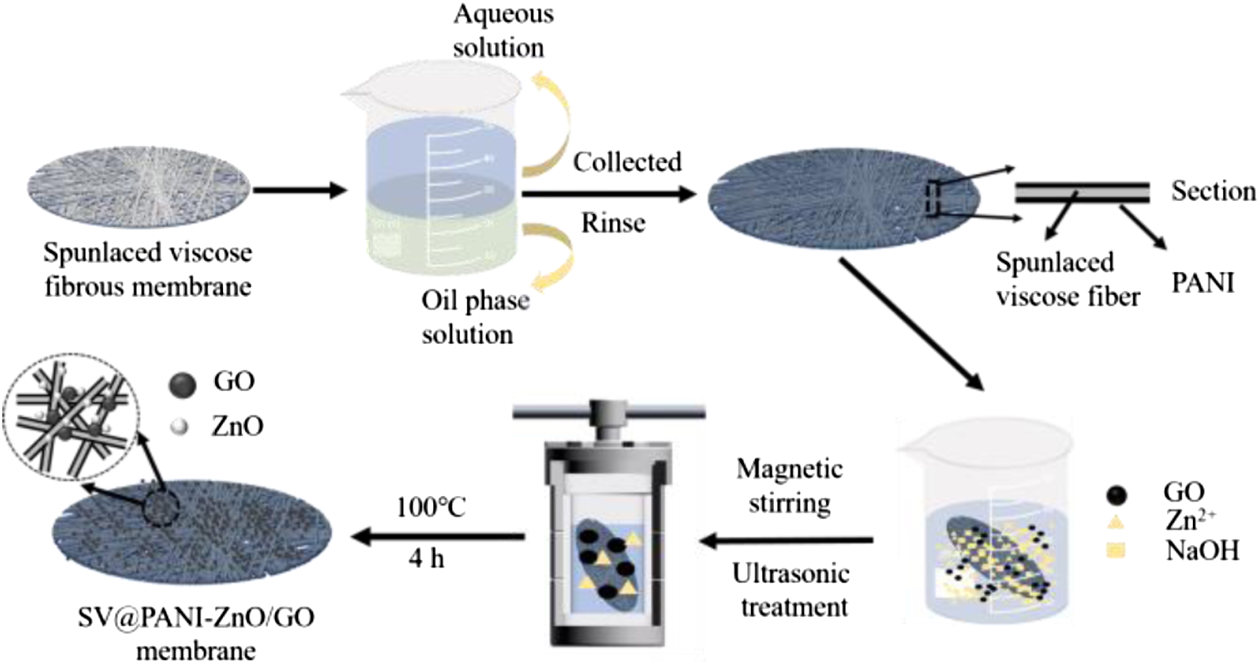
Characterization
The phase composition of membranes was measured by German Bruker D8 series X-ray diffractometer, and the scanning range was set at 20–80°. The morphology and element composition of the membranes were characterized by Hitachi (Japan) S-4800 scanning electron microscope (SEM) and energy dispersive spectroscopy (EDX), respectively. The thermal stability and the proportion of each component at 20–700°C were obtained by thermogravimetric analysis (TGA) using a Shimadzu (Japan) DTG-60H microcomputer differential thermal balance, and UV-Vis absorption spectra of all the membranes in the range of 200–800 nm was collected with a Shimadzu UV-3600 spectrophotometer. Reflectance measurement was performed on powdered samples while BaSO4 was used as a standard reference. Fourier transform infrared (FTIR) spectra was measured by a Shimadzu IR Prestige-21 Fourier transform infrared spectrometer with the KBr pellet technique in the range of 4000–800 cm−1. The specific surface area of all prepared membranes was tested by NOVA2000e specific surface area and pore size analyzer (Quantachrome, USA).
Photocatalytic test
The photocatalytic test was carried out in a BL-GHX-V multifunctional photochemical reactor at room temperature. The photocatalytic performances of the different samples (SV@PANI membrane, SV@PANI-ZnO membrane, SV-ZnO membrane, and SV@PANI-ZnO/GO membrane) were measured by the degradation of MB, as a representative organic pollutant, under UV irradiation (300 W, mercury lamp). A magnetic stirrer was equipped at the bottom of the reactor to achieve the flow of solution, and the flowing circulating water outside the lampshade could ensure that the heat generated by the lamp will not change the conditions of photocatalytic degradation.
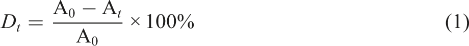
Firstly, 50 mg photocatalytic membranes were put in 50 mL 5.0 mg·L−1 MB solution, being stirred for 30 min under dark conditions to achieve the adsorption–desorption equilibrium before illumination. The 3 mL solution was taken out at regular intervals and analyzed by a UV-5500 spectrophotometer at 664 nm. The decolorization rate of the prepared membranes was calculated using equation (1)
Effect of pH on photocatalytic decolorization
In the photocatalytic process, it is necessary to explore the decolorization performance under different pH, which could affect the formation of active species and the surface charge of the catalyst. Following, the pH of the MB solution was changed from 1.50 to 9.68 to investigate the influence of pH on photocatalytic decolorization of the SV@PANI-ZnO/GO membrane.
Evaluation of photocatalytic active species
In order to clarify the mechanism of the photocatalytic process, the free radical capture experiment was carried out on the SV@PANI-ZnO/GO membrane. The trapping agents added in the photocatalytic experiment are 1.00 mM BQ (O2-), TBA (.OH), and Na2-EDTA (h+).
Results and discussion
Scanning electron microscope and energy dispersive spectroscopy characterization
The morphology of spunlaced viscose fiber, SV@PANI membrane, and SV@PANI-ZnO/GO membrane was observed by using SEM. It can be seen from Figure 2(a) that the surface of spunlaced viscose fiber is clean, smooth, and well-shaped. Figure 2(b) shows that the surface of spunlaced viscose fiber was covered with PANI after modification, the fiber is tightly wrapped with a layer of PANI, and the surface becomes rough. It is worth mentioning that there are many network structures of PANI polymer formed, which could be used as an electronic transmission channel and provide a good binding site for ZnO and GO. As shown in Figure 2(c), ZnO was germinated on fibers of SV@PANI membrane with sizes being about 10–20 nm, are uniformly distributed, and the flower-like aggregation. This shape promotes effective contact between the reaction substrate and the membrane. As we expect, the in-situ growth and hydrothermal method do not damage the structure of spunlaced viscose fiber. Scanning electron microscope and energy dispersive spectroscopy of spunlaced viscose fiber (a) (d), SV@PANI membrane (b) (e), and SV@PANI-ZnO/GO membrane (c) (f).
EDX analysis was carried out to qualitatively analyze the element compositions of spunlaced viscose fiber (Figure 2(d)), SV@PANI membrane (Figure 2(e)), and SV@PANI-ZnO/GO membrane (Figure 2(f)). During the EDX analysis, it can be seen from Figure 2(d) that spunlaced viscose fiber mainly contain carbon (C) and oxygen (O) elements. When PANI was formed on spunlaced viscose fiber, nitrogen (N) element has appeared and the content ratio of C and O was changed (Figure 2(e)), the presence of element sulfur (S) may be caused by APS. Figure 2(f) confirms the presence of C, N, O, and Zinc (Zn) elements on the SV@PANI-ZnO/GO membrane, which proves that ZnO nanoparticles have been successfully fabricated. Besides, the results reveal that the mass ratio of element Zn is 29.5% in the SV@PANI-ZnO/GO membrane.
Fourier transform infrared and UV-vis studies
Figure 3(a) shows UV-Vis absorption spectra of the prepared membranes. It can be found that ZnO/GO has a slight red shift, and the absorption capacity of UV light is increased owing to the combination of ZnO and GO. Additionally, it is worth noting that from the curve of the SV@PANI-ZnO/GO membrane, the ability to absorb ultraviolet light is still be maintained. UV-Vis spectrum of ZnO, ZnO/GO, and SV@PANI-ZnO/GO membrane (a) and FTIR of spunlaced viscose fiber, SV@PANI membrane, and SV@PANI-ZnO/GO membrane (b).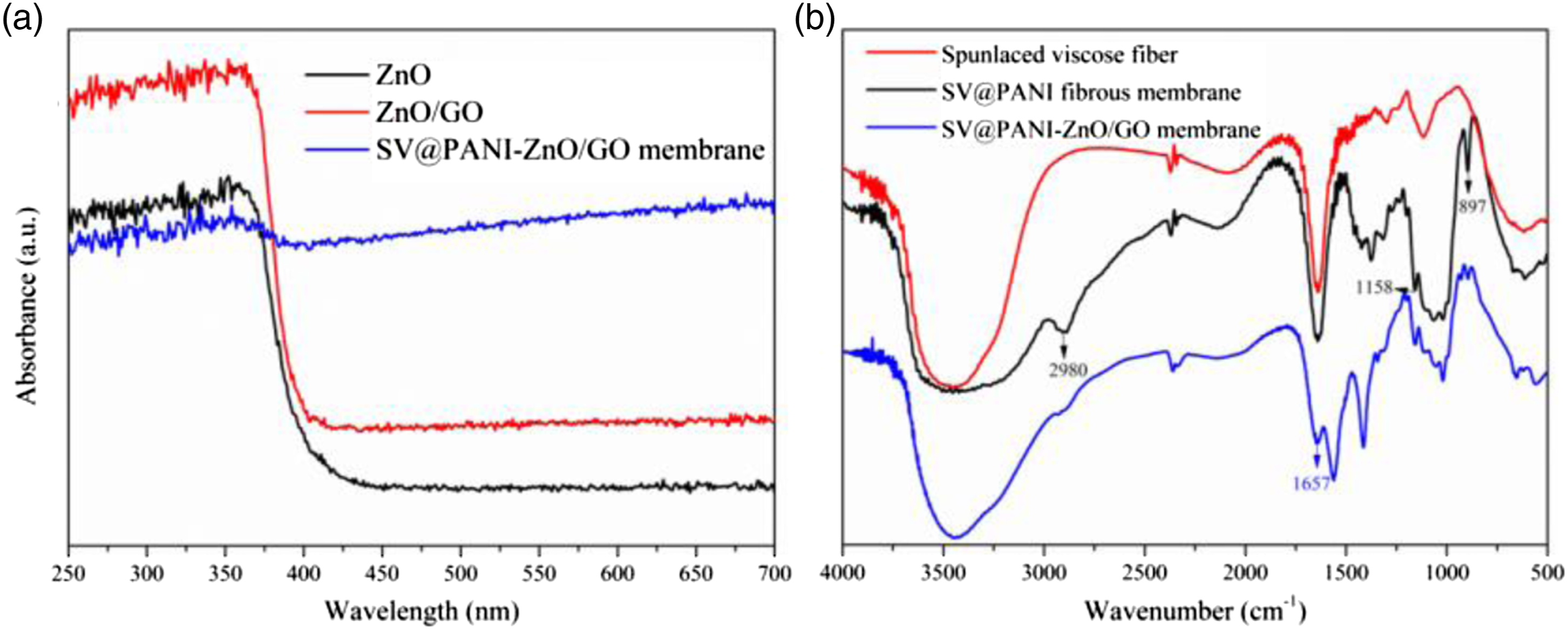
Figure 3(b) depicts the FTIR spectra of spunlaced viscose fiber, SV@PANI membrane, and SV@PANI-ZnO/GO membrane. It can be observed that there is one main characteristic adsorption band centered at the wavenumber of 3500 cm−1, which could be attributed to the groups of O-H or N-H. From the spectrum of SV@PANI membrane, the C-H stretching vibration peak (centered about 2980 cm−1), C-N absorption peak (at the wavenumbers of 1370 cm−1), and C-H out-of-plane bending vibrations (at the wavenumbers of 897 cm−1) on polyaniline benzene ring could be observed. Besides, the C = N stretching vibration peak on the quinone ring at the wavenumbers of 1158 cm−1 also appeared, indicating that the quinone and benzene ring coexist in the PANI (the prerequisite for PANI owning conductive properties). As shown in the FTIR spectra of SV@PANI-ZnO/GO membrane, the characteristic bands at 1657 cm−1 should be attributed to the existence of C = O, which confirms GO has been successfully loaded.
XRD and thermogravimetric analysis
Figure 4(a) shows TG curves of SV@PANI membrane, SV@PANI-ZnO/GO membrane, and ZnO/GO. In the curve of ZnO/GO, two decomposition processes occurred in 40–100°C and 380–400°C, respectively. The first mass decrease was caused by the evaporation of water, and the mass decrease in the range of 380–400°C should be ascribed to the decomposition of GO. The curve of SV@PANI membrane is consistent with that of SV@PANI-ZnO/GO membrane before 620°C could be roughly divided into two processes: (1) evaporation of water molecules in the sample reduces the quality of membranes before 100°C; (2) in the range of 250–620°C, the molecular of fibrous chains was broken and the mass of the membrane was gradually reduced. After the reaction, 30% SV@PANI-ZnO/GO membrane was retained which was attributed to the residue of ZnO. TG curves of SV@PANI membrane, SV@PANI-ZnO/GO membrane, and ZnO/GO (a) and XRD spectrum of ZnO, ZnO/GO, and SV@PANI-ZnO/GO membrane (b).
As shown in Figure 4(b), XRD was used to analyze the crystallographic structure and phase composition of ZnO, ZnO/GO, and SV@PANI-ZnO/GO membrane. The characteristic peaks of ZnO are highly consistent with the wurtzite ZnO on the standard card at 2θ=31.8°, 34.4°, 36.2°, 47.5°, 56.5°,62.8°,67.9°, and 69.0°, which should be attributed to the (100), (002), (101), (102), (110), (103), (112), and (202) crystal plane (JCPDS Card No.36-1451). Therefore, it confirms that the hexagonal wurtzite ZnO phase was successfully prepared by the hydrothermal method.29,30 Besides, the XRD spectrum of ZnO/GO exhibits the characteristic absorption peak of GO at 8°, and no characteristic peak of reduced graphene oxide was found at 25°, which proves that its oxidability is well preserved. In the pattern of SV@PANI-ZnO/GO membrane, all the characteristic peaks of ZnO could be seen, demonstrating that ZnO loaded onto the membrane maintained its wurtzite phase properties. The peak of GO at 8° is not apparent due to the small content of GO that existed in the membrane.
BET analysis
Specific surface area of spunlaced viscose fiber, SV@PANI, SV@PANI-ZnO, and SV@PANI-ZnO/GO membrane.

Photocatalytic properties
Decolorization performance and process
The photocatalytic activities of different membranes were evaluated by the catalytic degradation of MB, as shown in Figure 5(a). It can be seen from Figure 5(a) that the decolorization rates of SV-ZnO membrane and SV@PANI-ZnO membrane were 63% and 85% within 120 min, respectively. The reason is that PANI may effectively inhibit the recombination of photogenerated electrons and holes; thus, improving the photocatalytic performance of the materials. Moreover, SV@PANI-ZnO/GO membrane shows better photocatalytic performance, and its decolorization rate reaches 97%. This should be attributed to the addition of the GO, not only bringing about an increase of light absorption but also benefiting to absorb more dye molecules. Additionally, Figure 5(c) shows the absorption spectra of MB solution along with the time by using SV@PAN-ZnO/GO membrane, the phenomena also shows that MB could be effectively degraded within 120 min. Photocatalytic degradation rates (a) and pseudo-first order kinetic fitting process (b) of different samples toward MB; the absorption spectra of MB solution along with the time (c) and the effect of pH on MB decolorization rate (d) by using SV@PAN-ZnO/GO membrane.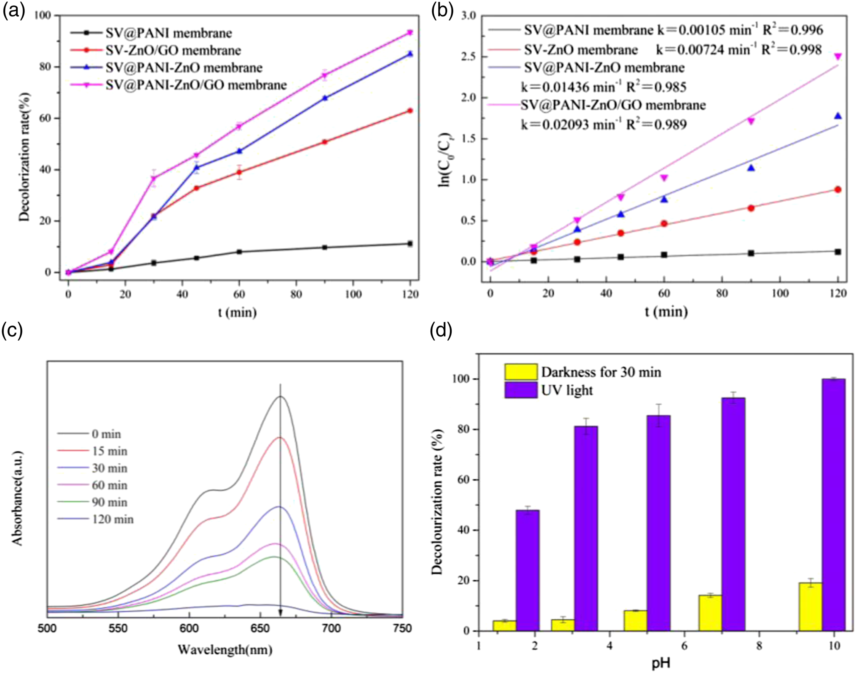
To better understand the photocatalytic dynamic process of the membranes, the first-order kinetic model with ln(C0/Ct)=kt (where C0 is initial solution concentration, C is the concentration of solution at time t, and k is the kinetic constant) is used to describe the experimental data, as shown in Figure 5(b). It shows the plot of ln ln(C0/Ct)=kt against reaction time in the photocatalytic decolorization process of MB presents linear relationship. In other words, the constant k is usually positively correlated with the degradation rate.21,32 The results show the apparent rate constant of SV-ZnO, SV@PANI-ZnO, and SV@PANI -ZnO/GO membrane are 0.00,724, 0.0143, and 0.0209 min−1, respectively. As we known, the photocatalytic decolorization process can be divided into adsorption and degradation procedure. Compared with SV-ZnO and SV@PANI-ZnO membrane, PANI helps to increase the decolorization rate due to its good electron transfer property. The constant k of SV@PANI-ZnO/GO membrane is the highest among other membranes, because GO will not only improve the transfer of electrons but also contribute to the adsorption of dye molecules.33,34
Figure 5(d) depicts the effect of pH on MB decolorization rate. The adsorption and degradation effects of SV@PANI-ZnO/GO membrane on MB have reached the maximum when we adjusted the pH up to 9.68. The pH of the MB solution could affect the adsorption of the catalyst, and a good adsorption effect will also help enhance the photocatalytic degradation performance. 31 Specifically, ZnO is easy to adsorb the electrically positive MB onto the surface by electrostatic action in alkaline conditions. In addition, it is beneficial for the h+ to migrate to the surface of ZnO and react with electron receptors such as H2O and OH− so as to produce .OH with strong catalyst. Therefore, the stronger the alkalinity, the better the degradation effect of the catalyst within a certain range.
Identification of reactive species
Figure.6 shows the effect of various reactive species inhibitors on photocatalytic performance. When the capture agent TBA, BQ, and Na2-EDTA (corresponding to .OH, O2- and h+) were added, the corresponding MB degradation rates are 33.2%, 68.1%, and 93.2%, respectively. It can be seen that the presence of TBA significantly inhibited the photocatalytic activity of SV@PANI-ZnO/GO membrane, and the decolorization rate dropped from 97% to 33.2%. Furthermore, the presence of BQ has a slight effect on the photocatalytic decolorization, and the presence of Na2-EDTA (h+) hardly affects the photocatalytic activity. It can be determined that .OH is dominant in the photocatalytic process of SV@PANI-ZnO/GO membrane and the effect of the active group capture order is .OH >·O2- > h+. Reactive species capture of SV@PANI-ZnO/GO membrane during MB decolorization.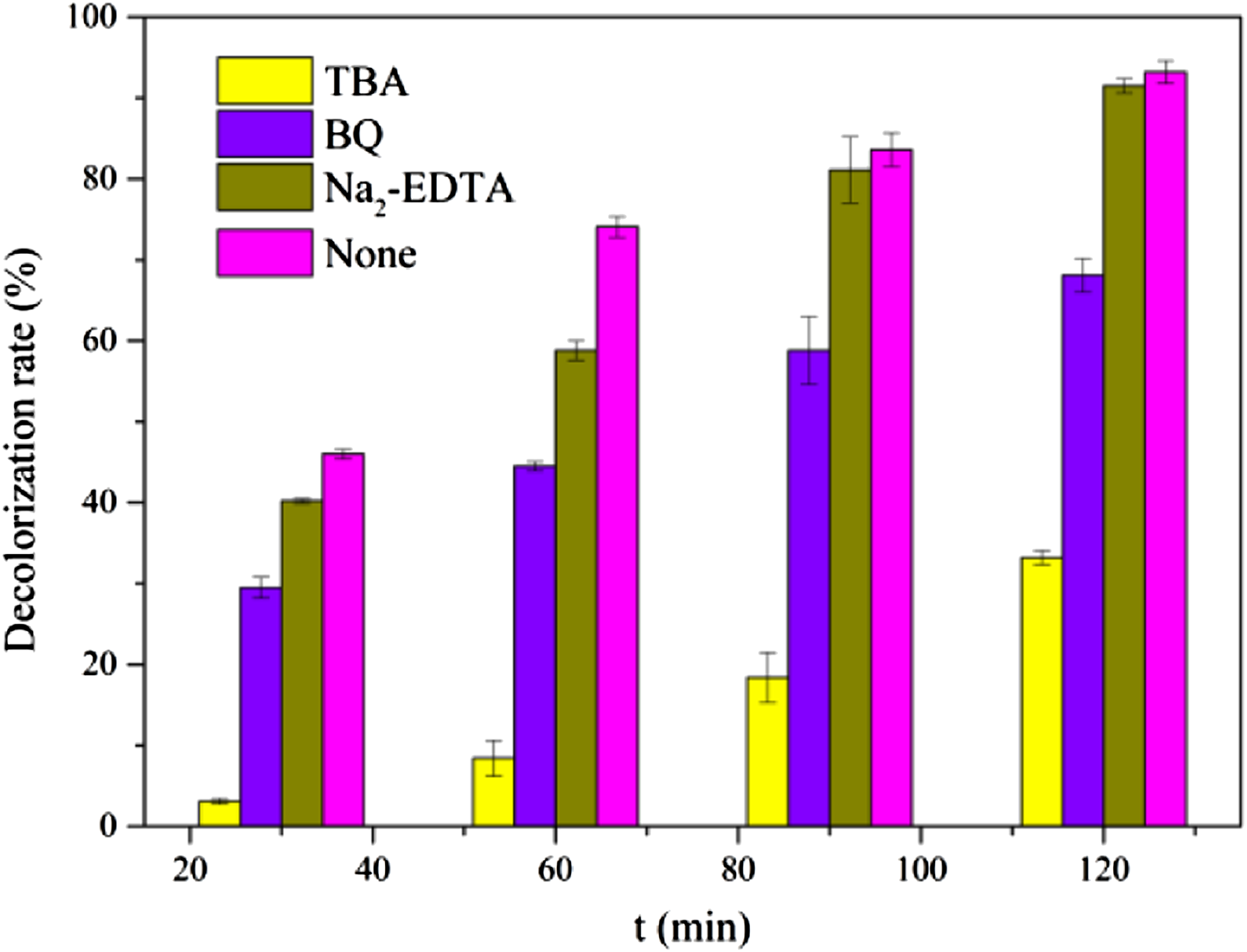
Reusable performance of membrane
The cycling tests were carried out to study the reusability of the prepared membrane. The result is shown in Figure 7, the decolorizing ability of SV-ZnO membrane remained above 49%, whereas SV@PANI-ZnO and SV@PANI-ZnO/GO membrane remained approximately 69.8% and 76.7% after 5 cycles, respectively. This apparent increase may be attributed to the network of PANI, which has a good load and support capacity for ZnO and GO. It indicates that the SV@PANI-ZnO/GO membrane prepared in this experiment could be used for several cycles and has good photocatalytic reusability. Stability of SV-ZnO, SV@PANI-ZnO, and SV@PANI-ZnO/GO membrane.
Photocatalytic mechanism analysis
From the above analysis and discussion, we put forward the feasible photodegradation mechanism of MB by SV@PANI-ZnO/GO membrane under UV light, as shown in Figure 8. When the photocatalytic system is stimulated by UV light, the electron-hole pairs produced by ZnO have been formed. Subsequently, the electrons are enriched to the conduction band (CB) of ZnO or transported on the surface of GO, resulting in redox reaction. Meanwhile, the h+ of ZnO flow into Highest Occupied Molecular Orbital (HUMO) of PANI could react with H2O to generate .OH radicals, which are the most important active radicals during photocatalysis.25,28,35 In addition, PANI and GO have strong adsorption capacity for MB, making them quickly mineralized and degraded. The mechanism of photocatalytic process.
Conclusion
Herein, we synthesized spunlaced viscose/polyaniline composite fibrous membrane by in-situ growth method, and the ZnO and GO were then loaded on the fibrous membrane via hydrothermal method. The results show that the fabricated membrane exhibited good fibrous morphology, light absorption capacity, and thermal stability. Furthermore, the decolorization rate of SV@PANI-ZnO/GO membrane for MB (5 mg/L) was 97.3% under UV light irradiation within 120 min. After 5 cycles, SV@PANI-ZnO/GO membrane still maintained relatively high catalytic activity and the removal rate of MB remained above 76.7%. In a word, SV@PANI membrane can effectively enhance the photocatalytic efficiency of the ZnO while avoiding the phenomena of photocatalyst shedding and agglomeration. It will have good application prospect in the treatment of environmental wastewater, especially in the catalytic degradation of organic pollutants.
Footnotes
Declaration of conflicting interests
The author(s) declared no potential conflicts of interest with respect to the research, authorship, and/or publication of this article.
Funding
The author(s) disclosed receipt of the following financial support for the research, authorship, and/or publication of this article: This work was supported by the Natural Science Foundation of Anhui Provincial Education Department (grant number 2008085ME139), “Textile fabric” key Laboratory of Anhui polytechnic University, and Opening Fund Project of Anhui Textile Engineering Technology Research Center (grant number KZ00418043).