
Abstract
Nowadays, using three dimensional fabric as a reinforcement part in the composite has been increased. Non-crimp three dimensional orthogonal woven fabric is a subgroup of 3D woven fabrics that in this study was used to fabricate composite preforms. The fabrics were produced by glass yarn in two different fiber volume fractions. All fabric preforms were utilized to produce composites with polyester and epoxy resins. To compare the torsional behavior of the composites, a torsion test was applied to all samples and torque-revolution curves from the experimental results were compared together. Results showed that composites that were fabricated by epoxy resin have more torsional strength in comparison with composites in that their matrix is polyester resin. Moreover, preforms with high fiber volume fractions showed high torsional strength in each type of matrix. The torsion strength of high volume fraction for polyester matrix was 47.34 KPa, however for the sample with epoxy matrix the torsion strength was determined 81.26 KPa. Furthermore, a multiscale finite element model was applied to calculate elastic constants and predict the torsional behavior of the composites. The numerical results were compared with experimental results that a good agreement between numerical and experimental results was observed. Therefore, the proposed model can predict the torsional behavior of the composite with different fiber volume fractions.
Keywords
Introduction
In the recent era, composite materials have been used in many industries extensively.1–3 Lightweight besides high mechanical properties of textile preform lead to having been considered by many researchers to use them as a reinforcement part for composite structures.2,5 3D textile composite is one of the subgroup of composites that could be fabricated by various methods such as weaving, knitting, and braiding. 6 Textile architecture and the orientation of fibers play a considerable role in the composite’s mechanical features. Yarn crimp is one of the effective parameters on stiffness and strength of the composite that can reduce these mechanical properties. Moreover, by adding straight yarns within the composite structure, volume fraction, stiffness, and strength of the composite are increased.7–9 So, it can be concluded that textile structures with more number of straight yarns, have high mechanical properties.
Non-crimp three dimensional orthogonal woven (NC3DOW) fabric is a subgroup of 3D woven textiles in which yarns are aligned straightly in the fabric structure. Non-crimp yarns indicate maximum resistance under external load in different directions. Moreover, designing a composite with a high fiber volume fraction in this fabric is easier than others.10,11 Some studies have been conducted to investigate the mechanical behavior of NC3DOW fabric. Karahan et al. 12 investigated the internal geometry of NC3DOW composite by image processing. They compared the geometry of this fabric with other 2D and 3D fabrics. They also in another study examined fatigue tensile performance of carbon/epoxy composite with NC3DOW preform. 13 The impacts of temperature on the fatigue behavior of an NC3DOW composite were assessed by Wilkinson and Ruggles-Wrenn. 14 The results showed that increase in temperature imposed a slight impact on the composites’ on-axis tensile features. The impact properties of this structure are other considerable properties that were studied by Hu et al. 15 Minapoor et al., in another work, 10 investigated the tensile strength of a novel NC3DOW with two different yarn densities. This fabric was produced by a self-designed loom. The yarns are aligned in three different directions and the fiber volume fraction of the preform can be changed by changing the yarn orientation angle.
On the other hand, computational methods have been had a great effect on predicting the thermal and mechanical features of the composite preforms. In this vein, the finite element method is one of the numerical approaches that have been used widely by researchers in this field.5,16–20 Multi-scale finite element modeling is a subgroup of the finite element method that improves the accuracy of the model to predict the final properties of the composite. In this technique, a unit-cell of the composite includes fibers and matrix at the meso scale is modeled and mechanical properties of the composite such as elastic constants or failure parameters are extracted from the unit-cell. Afterward, the actual load based on the experimental procedure is applied to the macro model to analyze the mechanical behavior of the composite.17,21–24
According to previous studies, the majority of research has been focused on tensile and flexural properties of the NC3DOW composites and there are limitation papers that have investigated other properties such as the torsional behavior of NC3DOW composites. The torsional behavior of the composite shows the effect of fiber orientation and shear stiffness of the composite. Therefore, in this paper torsional behavior of NC3DOW composites with two different fiber volume fractions and two matrixes was examined. The structure of the NC3DOW fabric was mentioned in Ref. 10. Besides, a multi-scale finite element modeling was utilized to predict the linear behavior of the composites under torsional load.
Materials and experimental procedure
For experimented work, glass yarns were used to produce NC3DOW fabric. The NC3DOW samples were fabricated by a self-designed loom based on the uniaxial noobing process.
25
In this fabric, there are three sets of non-crimp yarns that are aligned in x, y, and z directions. The tension of longitudinal yarns is defined in two terms, namely no-stress state and prestress state. No-stress state means the longitudinal yarns (Z-yarns) set on the loom smoothly and without any stretching. In pre-stress state, glass tows are subjected to 120 N force according to their force-elongation curves and then the weaving process is done. The specific structure of the fabric leads to fabricate a fabric with a high volume fraction of fiber. Indeed, the absence of any interlacing (as woven fabrics), interlooping (as knitted fabrics), or intertwining (as braids) of the involved yarns causes more fiber content in these structures. In this loom, two lattice plates are set on top and bottom of the loom. The Z-yarns are passed through these plates. Two sets of tows are kept by two needle sets and during the weaving process are moved forward and backward. So, 3D non-crimp orthogonal fabric is made by this process. Figure 1 shows two views of the loom during the weaving process. Weaving process of the fabric by the self-designed loom, (a) side view and (b) bottom view.
Physical and mechanical properties of the glass yarn.

Fabric’s Structural parameters.


Real and schematic figure of the fabrics, (a) low volume fraction and (b) high volume fraction.
The mechanical and physical features of the epoxy and polyester resins.

The vacuum injection process (VIP) was used to manufacture all composites samples. The epoxy and polyester resins were thoroughly mixed with their corresponding hardener with a weight fraction ratio of 100:30. Then, prior to be used in the vacuum bag molding process, the deaeration process was performed by placing the prepared mixture in the vacuum oven under a pressure of 65 bar, at 30oC temperature for 15 min. The molded samples were kept at room temperature for 24 h to be cured. For improving their mechanical properties, the samples were then post-cured during further three different heating processes in an oven: for 2 h at 45°C temperature, for the next 2 h at 60°C temperature, and the final 8 h at 80°C temperature. Figure 3 shows NC3DOW fabrics and composite samples. (a) Vacuum injection process and (b) composite samples.
In order to obtain the torsional strength of the composites, a torsion test was performed on all samples based on ASTM D198 standard. In this test one side of the sample is fixed by a grip and a torque load with speed 0.2 rev/min is applied to the other side of the sample. The length and diameter of the samples were set 81 mm and 8.5 mm, respectively. The test setup is shown in Figure 3. For each composite structure, three specimens were tested and the average of outputs was reported (Figure 4). Torsional test. Multi-scale finite element model.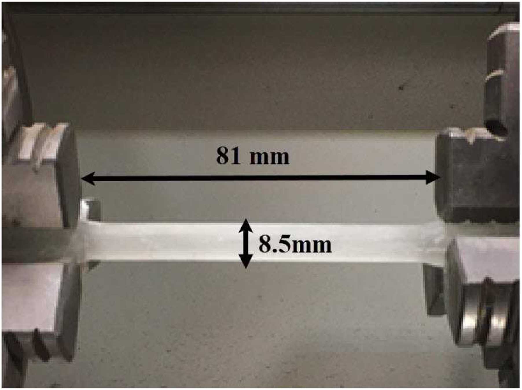
To obtain mechanical constants of the composite, a unit cell of the composite was modeled in ABAQUS finite element software. The diameter of the yarns is 1.1 mm
The yarn was impregnated with resin over the composite production procedure. The impregnated yarn was presumed as a unidirectional composite with fiber volume fraction equivalent to the yarn’s packing density

According to previous studies,5,18,27,28 the Chamis
29
model is a suitable model to calculate elastic constants of the resin-impregnated yarn. So, the Chamisa
29
micromechanical model is utilized for determining the elastic coefficients of unidirectional composites isotropic transversely.


The elastic coefficients of the resin-impregnated yarn.

To determine the constants of the composite’s stiffness matrix, periodic boundary conditions were applied to the meso model. The macroscopic strain increment was applied to the unit-cells by decomposing the displacement increment on the boundary into the macroscopic averaged displacement field and a period part repeated from one unit-cell to another one, such as The periodic boundary circumstances, (a) tensile load low volume fraction sample and (b) shear load on high volume fraction sample.


C3D8R element types in ABAQUS/Standard element library were utilized as an 8-node linear, to mesh the model. Figure 6 represents the unit-cell followed by the meshing procedure. Through a Mesh dependency investigation on the model, the results are assured to be mesh size independent. Table 5 shows the elastic moduli calculated for HVF sample with epoxy resin in different mesh sizes. The periodic boundary circumstances, (a) tensile load and (b) shear load. Mesh size for different model and prediction of elastic moduli for each model.

Based on Table 5, there is a small difference between the results of models 2 and 3. So, mesh size for model 3 was chosen for meshing the unit-cells. Next, the embedded element technique was applied, considering the yarn parts as the embedded region and the matrix part as the host. However, to eliminate the volume redundancy caused by the embedded element technique, 30 the stiffness of the epoxy resin was subtracted from the stiffness matrix of the unidirectional composite yarns.
The representative unit cells of composite specimens are assumed as orthotropic and homogenous. Therefore, the stiffness matrix for an orthotropic substance is represented in equation (11)
31

For the homogenous composite materials, the association between average strain and stress is


At the macro model, a 3D cylinder geometry regarding the dimensions of the experimental sample was created. The elastic constants that were extracted from the meso model were assigned to the macro model. To simulate the torsion test, all degrees of freedom of one side were fixed and a torque load was applied to another side. The meso model was meshed using C3D8R element type in ABAQUS/Standard element library (an 8-node linear). Figure 7 shows the applied load and the macro model after mesh generation. Mesh generation on the unit cell.
Result and discussion
Figure 8 shows Torque- Revolution curves for composite samples with two different matrices. (2π radians becomes one revolution). It should be noticed that the average values were used for Figure 9. Loading and mesh generation on the macro model. Torque-Revolution for composite samples with (a) polyester resin and (b) epoxy resin.

According to Figure 8, composites with epoxy matrix show more torsional strength and revolution in comparison with composites with the polyester matrix. Moreover, the stiffness of the composites with the epoxy matrix is more than composites with the polyester matrix. It is obvious that the reason for this phenomenon is the high young modulus of epoxy resin. Furthermore, the increasing volume fraction of the fibers leads to more torque is needed to apply in order to fail the composite. In order to increase the volume fractions of the fiber in the composite structure, the orientation angle of weft and warp yarn should be changed during the fabrication process. Change the orientation angle of weft and warp yarns causes to align a greater number of fibers through the applied load. Therefore, a greater number of fibers contribute to reinforcing the composite and eventually improves the torsional strength. The shear stress of the composite sample under torsion load can be calculated as follow.
33

Experimental test results.

During the torsion test, extreme shear stress is applied to the composite. Based on observations from the test, in the initiation point of failure, cracks appeared through the composite that shows the matrix damage. Afterward, transverse and shear stress from the torsional load cause to damage occurs on fibers. The higher modulus of glass fiber than matrices creates a stress transfer near the fibers. 35 Thus, crack propagation through the various directions is more dominant than crack propagation mainly in one direction. High fiber volume fraction increases the crack distribution within the composite and plastic behavior of the composite. 35 The fiber orientation of the NC3DOW fabric in different directions contributes to stress transfer better than unidirectional composite. Eventually, by increasing the torsional load, the cracks propagate through the composite and failure is occurs on the matrix and fibers. Figure 9 shows the composite after a fracture.
In order to analyze the failure mechanism of the composite, the fracture surface was observed using a scanning electron microscope (Figure 10). The composite after fracture for low volume fraction with epoxy resin.
According to Figure 10(a), once a torsional load is applied to the composite, the weft yarns are deformed and aligned through the applied load. These yarns resist external load until the fracture occurs within the composite and yarns are damaged. Figure 10(b) shows a crack that is propagated within the impregnated yarn and the matrix, and fiber failure could be observed.
As was mentioned, a multi-scale finite element model was applied to predict the torsional behavior of the composites. Figure 11 and Figure 12 show stress contours for matrix and fabric in meso scale. Scanning electron micrographs of fractured surfaces of the composite, (a) composite failure and (b) fiber failure. Stress contours for matrix and fabric of the model with high volume fraction of yarn, (a) under tensile load through the first direction, (b) under tensile load through the second direction and (c) under shear load (unit: MPa).


Predicted stiffness matrices for low and high-volume fraction with epoxy and polyester matrix.
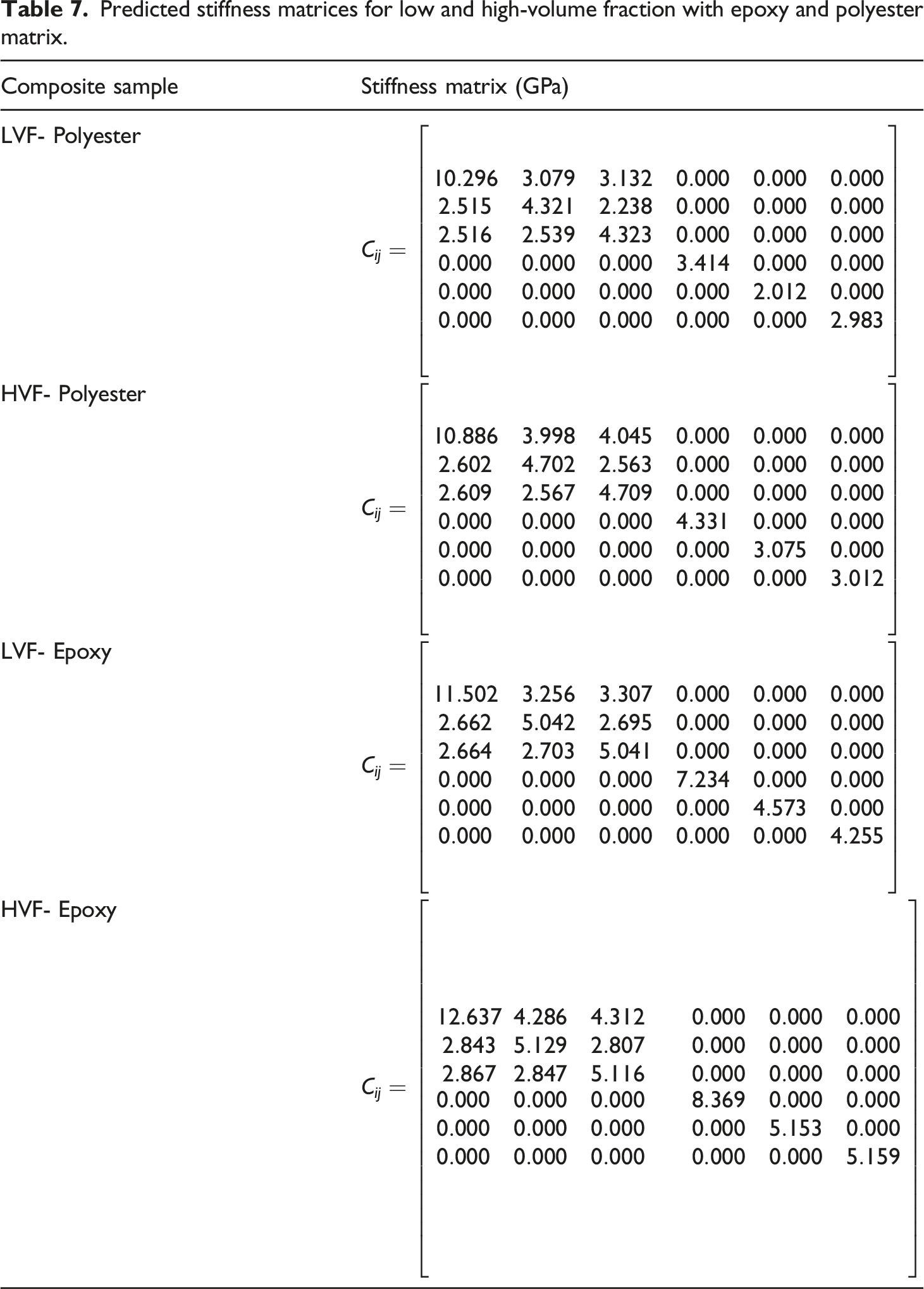
The stiffness matrices which were shown in Table 7 were utilized for the macro model. Stress contours of the macro model under a torsional load for high volume fraction epoxy composite are presented in Figure 13. Stress contours for matrix and fabric of the model with low volume fraction of yarn, (a) under tensile load through the first direction, (b) under tensile load through the second direction and (c) under shear load (unit: MPa).
To evaluate the accuracy of the numerical model, the torque-revolution curves of the FE model were compared with experimental results. The torque-revolution curves for numerical and experimental results are shown in Figure 14. Stress contours of HVF-epoxy sample in the macro scale (unit: MPa).
Comparison between experimental and numerical results at 0.05 revolution.

Table 8 shows that the proposed model could predict linear behavior of the composites under torsional load and the error values for all samples are under 8%. This model can be applied for the elastic behavior of the composite and to predict the failure and nonlinear stages, more supplements codes will be needed to add to the model. However, according to Figure 15, it seems that the stiffness of the numerical model is more than the experimental results. During the fabrication process, some fibers can be damaged because fibers are under tensile and bending loads. This issue reduces the mechanical properties of the fabric and the stiffness of the composite. The fiber damage during the fabrication process reduces the yarn strength that leads to reduce the composite strength. Moreover, the cross section of the yarns was assumed as a circular shape which is not perfectly circular. Cross section of yarns changes the polar moment of inertia that this fact changes the shear stress and torsion strength of the composite. So, this assumption can make an error in numerical results. Besides, some void can be created during the fabrication process which can reduce the mechanical properties of the composite. The presence of void in the composite is a factor for stress concentration which is the start point for crack propagation within the composite. Comparison between torque-revolution curves of experimental and numerical results for low and high-volume fraction with epoxy and polyester matrix.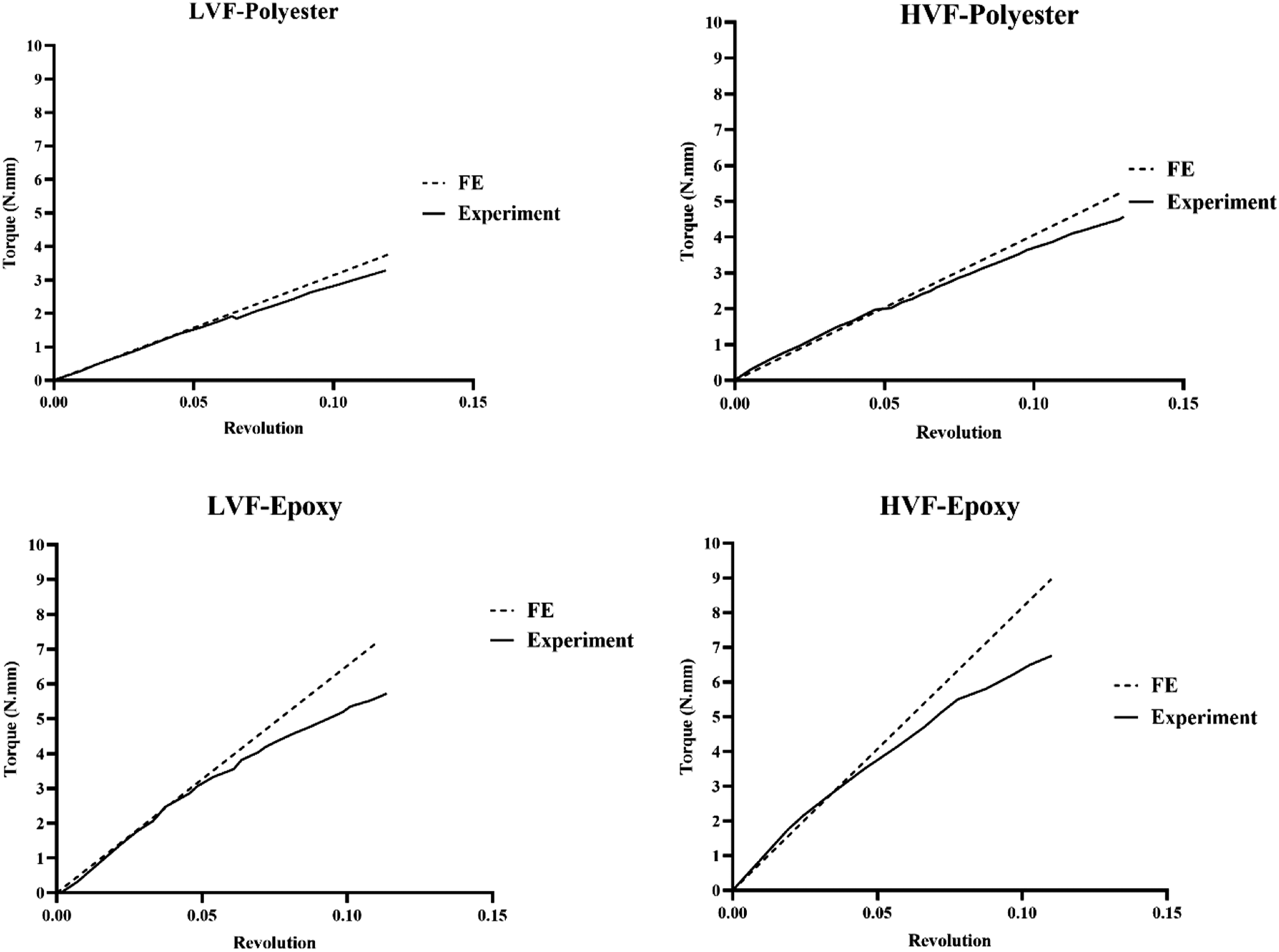
Conclusion
This paper is an effort to investigate the torsional behavior of NC3DOW composite experimentally and numerically. In this study, two different volume fraction composites were fabricated with polyester and epoxy resins. The experimental results showed that using epoxy resin improves torsional strength in comparison to polyester resin. Moreover, the composites which were produced by polyester resin showed a brittle failure in comparison to epoxy resin. This phenomenon shows that the bonding strength between glass fibers and epoxy is more than glass fibers and polyester. The high bonding strength leads to cracks are distributed in different areas and a nonlinear behavior can be observed near the failure point of the composite. Furthermore, increasing the volume fraction of fibers leads to improve torsional behavior of the composite in the same matrix. The torsional strength for high and low volume fraction composite with epoxy matrix was 81.26 and 66.60 MPa, respectively. Moreover, the torsional strength for high and low volume fraction composite with polyester matrix was 47.34 and 34.97 MPa, respectively. In the composite with a high volume fraction of fiber, a high number of fibers contributes to preventing the crack growth continuously and distributes cracks within the composite. Therefore, the torsional strength of the composites with high fiber volume fraction is more than the composites with low fiber volume fraction. During the failure process, some cracks occurred through the matrix, and by increasing torsional load the cracks are propagated within the fibers and failure is occurred in the composite. Besides, a multi-scale finite element model was applied to predict the torsional behavior of the composites. The error value between the numerical and experimental model for the linear regime of the torque-revolution was less than 7%. This output indicates that the proposed model capable to predict the torsional behavior of the composites in the linear section.
Footnotes
Declaration of conflicting interests
The author(s) declared no potential conflicts of interest with respect to the research, authorship, and/or publication of this article.
Funding
The author(s) received no financial support for the research, authorship, and/or publication of this article.