
Abstract
Non-crimp 3D orthogonal fabrics are high-tech textiles with three sets of orthogonal yarns. 3D composites reinforced by this fabric have a high performance and wide usages due to their structure. This study attempted to investigate the torsional behavior of Glass/epoxy composite rods reinforced by 3D fabrics experimentally and numerically. Accordingly, three different 3D weaves, including low-density and high-density non-crimp 3D orthogonal, and braid-pultruded fabrics were tested by a torsion tester machine. The results showed that non-crimp 3D orthogonal composites, especially those with a higher density, had better torsional properties than the others, due to the square cross-section and perpendicular fiber involvement in all directions. Optimal torsional properties were obtained for the high-density non-crimp 3D orthogonal composite with the lower void content. Also, a python code was developed to simulate the torsional behavior of the rod composite in macro-scale based on the geometry of the unit cell and the mechanical constants obtained from the meso-scale.
Keywords
Introduction
Along with the requirements for employing multifunctional structures in different technical applications, textile reinforced composites, due to their light-weight characteristics as well as providing good mechanical performances, has attracted the interest of numerous researchers who are concerned with developing composite materials. The expanded use of composites in marine and aircraft structures has heightened interest in using composites to replace metals in automobiles, trucks, and buses. Increasing developments in composite manufacturing industries have caused the shifting of the research activities from 2D composite materials to complexed-shaped 3D items which can be used in high-performance applications with multifunctional requirements. Three-dimensional composites have shown both increases and decreases in elastic modulus, tensile strength, and compressive strength compared with the conventional 2D laminated composites [1]. The importance of weight reduction in the case of technical products while keeping their strength and performance quality, is claimed to be achieved by using composite textile. Some specified characteristics of these textiles, including low areal and bulk densities, comfort and thermo-physiological properties, improved tensile strength, elastic compress-ability, and high design-flexibility, have made them suitable to be widely employed as composite reinforcements [1–3].
Three-dimensional composites are a category of materials offering a potentially significant performance and manufacturing benefits for structural applications as they display a supreme performance at significantly reduced manufacturing costs and time [4]. As a less widely studied 3D fibrous reinforcement, non-crimp three-dimensional orthogonal woven fabrics, called NC3DOW, can be noted. The lack of crimp and straightness of the yarns in the structure can be due to its high strength, toughness, fatigue durability, slow progression of damage and failure, high energy absorption, and resistance to delamination. Such outstanding structural properties of these textiles make them suitable for use in various industries [5,6]. Khokar [7,8] proposed the term ‘‘noobing’’: non-interlacing, orientating orthogonally and binding, representing a non-crimp 3D orthogonal fabric’s structure. Having a non-crimp fabric as the composite reinforcement is beneficial because significantly higher stiffness and strength can be achieved. Noobing is a three-dimensional fabric-forming process that essentially assembles three mutually perpendicular sets of yarns. There is no interlacing (as with weaving), interloping (as with knitting), or intertwining (as with braiding) of the involved threads. Due to the great importance of NC3DOW fabrics and the unique applications of the composites reinforced with them in various industries, there has always been a need for a good understanding of their mechanical behavior. This fabric shows exceptional delamination suppression, leading to several benefits in the composite’s performance, such as increased fracture toughness, and improved impact resistance and damage tolerance, enabling machining without edge delamination [1,9].
The mechanical performance of the NC3DOW amplifier and its structural properties are considered as the main factors in the composite production processes, as well as the mechanical performance of the composite, to make the desired products. For example, the fiber volume fraction (FVF) is one of the most critical factors in the composite production processes, as well as the mechanical performance of the composite, as previously claimed by researchers [10–12]. Due to time and cost factors involved in the complete laboratory studies of the mechanical behavior of these composites and their dependence on all significant construction parameters, modeling methods have recently been developed to understand the mechanical behavior of these composites [13,14]. Given the importance, numerous applications, and complexity of the three-dimensional fabric reinforced composites, in recent years, researchers have decided to focus on the composites experimentally and numerically. One of the most important tests is the torsion test, which can extract the composite shear modulus [15–17].
Davalos et al. [18] examined the torsional properties of 3D composites. Their survey investigated the future of circular and square cross-sections; it has been stated that the shear stress at the corners of the square section is zero, and the maximum shear stress at the square area is along the centerline. Potluri et al. [19], Hao et al. [20], Zhao et al. [21] and He et al. [22] also investigated the effect of the cutting angle on the torsional properties of the braid reinforced composites. It has been stated that as the angle of the braid weave yarn approaches 45°, the shear modulus is increased. Stress is distributed uniformly in the radial direction throughout the sample, moving from the outer layers to the inner ones. Also, Zhao et al. [23] study on the torsion behavior of a 3D 4-directionally braided composite rod that is very similar to our structure shows that the affected area appeared on the left side of the braided shaft, where the angle of the affected area was close to 45°. As the torque increased, the affected area was increasingly identified. The whole process, shear strain, and axial displacement increased steadily. Finally, it has been concluded that yarns with a 45° angle could withstand the highest torsional stress; so, the use of yarns with higher modulus in this area has been recommended. Further, Shokrieh et al. [24] studied the torsional stability of a composite 3D braid drive shaft, comparing the findings obtained by FEM with the experimental and analytical results. It was revealed that the orientation of yarns and the number of non-reinforcing yarns affected the torsional torque intensity.Yoon1a et al. [25] also investigated the torsional behavior of 3D composite structures with arbitrary shapes using finite element (FE) models, defining a finite element nonlinear equation that could be applied to 3D dynamic composites under twisting. In addition, Minapoor et al. [26] simulated a finite element at the meso scale for NC3DOW; the simplified geometric model presented could predict the tensile behaviors of NC3DOW structures. Therefore, it would be helpful to predict the mechanical properties of both NC3DOW fabrics and composites.
Numerical modeling such as the finite element method is widely used to study the mechanical properties of different fabrics due to their complexity today. Mishra et al. [27] focus on geometric and micromechanical modeling of three-dimensional orthogonal fabrics for composite applications and use finite element modeling for it. The analysis is performed on single cells instead of whole fabric in ANSYS. El Hage et al. [28] and Lomov et al. [29] presented finite element models to predict the mechanical properties and fracture resistance of composites reinforced with NC3DOW. They showed that the overall behavior of the material can be predicted with meso-scale analysis with acceptable closeness to the experimental data also damage patterns inside the unit cell are described only qualitatively with the stiffness degradation scheme; however, the model adequately differentiates the transverse, shear, and fiber failure damage modes.
The mechanical behavior of NC3DOW reinforcement composites, due to the specific geometry of Z-binding and extreme straightness of the stuffing warp and weft yarns, is quite different. Detailed analysis of the mechanical behavior of this reinforcement has indicated the fabric behavior and performance in the composite manufacturing process and its technical applications. The aim of the current work was, therefore, to study the torsional behavior of an NC3DOW reinforcement composite experimentally and compare it with the Braid-Pultruded reinforcement composite to provide an introduction to the use of these shafts for power transmission in ultra-light machines with special performance or in strengthening advanced structures in aerospace science. Accordingly, NC3DOW E-glass samples with different weave parameters were subjected to the torsional test, and shear modulus was obtained. To provide a detailed understanding of the torsional properties of NC3DOW, a predictive model needed to be offered. In this study, a meso-scale finite element model was proposed to primarily analyze the mechanical behavior of NC3DOW and investigate the effect of the weave parameters on the geometric characteristics and shear modulus. Investigation of the torsion failure properties of NC3DOW reinforcements with various structural parameters could be, therefore, helpful for the analysis and design of composites regarding their final application.
Experimental
Production of NC3DOW and braid-pultruded samples
Properties of the E-glass fiber tow according to the ASTM D4018.

The order of the numbers in parentheses is CV%, CV: coefficient of variation.

Photograph of NC3DOW and Braid-pultruded E-glass samples and schematic of the warp/weft insertion density: (a) One layer per centimeter warp/weft insertion, low density of NC3DOW (LD), (b) two layers per centimeter warp/weft insertion, high density of NC3DOW (HD), and (c) braid-pultruded (BP).
Specifications of non-crimp 3D orthogonal and braid-pultruded E-glass samples.

Composite manufacturing
Molding operation of the composites reinforced with NC3DOW and braid-pultruded fabrics was obtained according to the ASTM E2207 and ASTM F383 [30,31] standards test method. A brass mold was designed according to the standard and fabric specifications, as shown in Figure 2(a). Based on the specific geometry and limitations of the mold, the manual injection method was chosen to inject the epoxy resin. The properties of the epoxy resin are shown in Table 3. To prevent slippage between the sample and the grips, two ends of the composite sample were designed as a prismatic shape. Sample’s Nominal dimensions were set at 81 mm in length and 8.5 mm in diameter, according to ASTM E2207 and ASTM F383. The details of the composite manufacturing are shown in Figure 2. Photograph of composite manufacturing: (a) Sample dimensions and design of the composite model, (b) brass mold, (c) Sample molding, (d) Locating the weave within the mold, (e) Injection of resin, (f) Bottom resin injection to remove air bubble, and (g) 3D Glass/Epoxy composite prepared for the torsion test. Properties of the epoxy resin.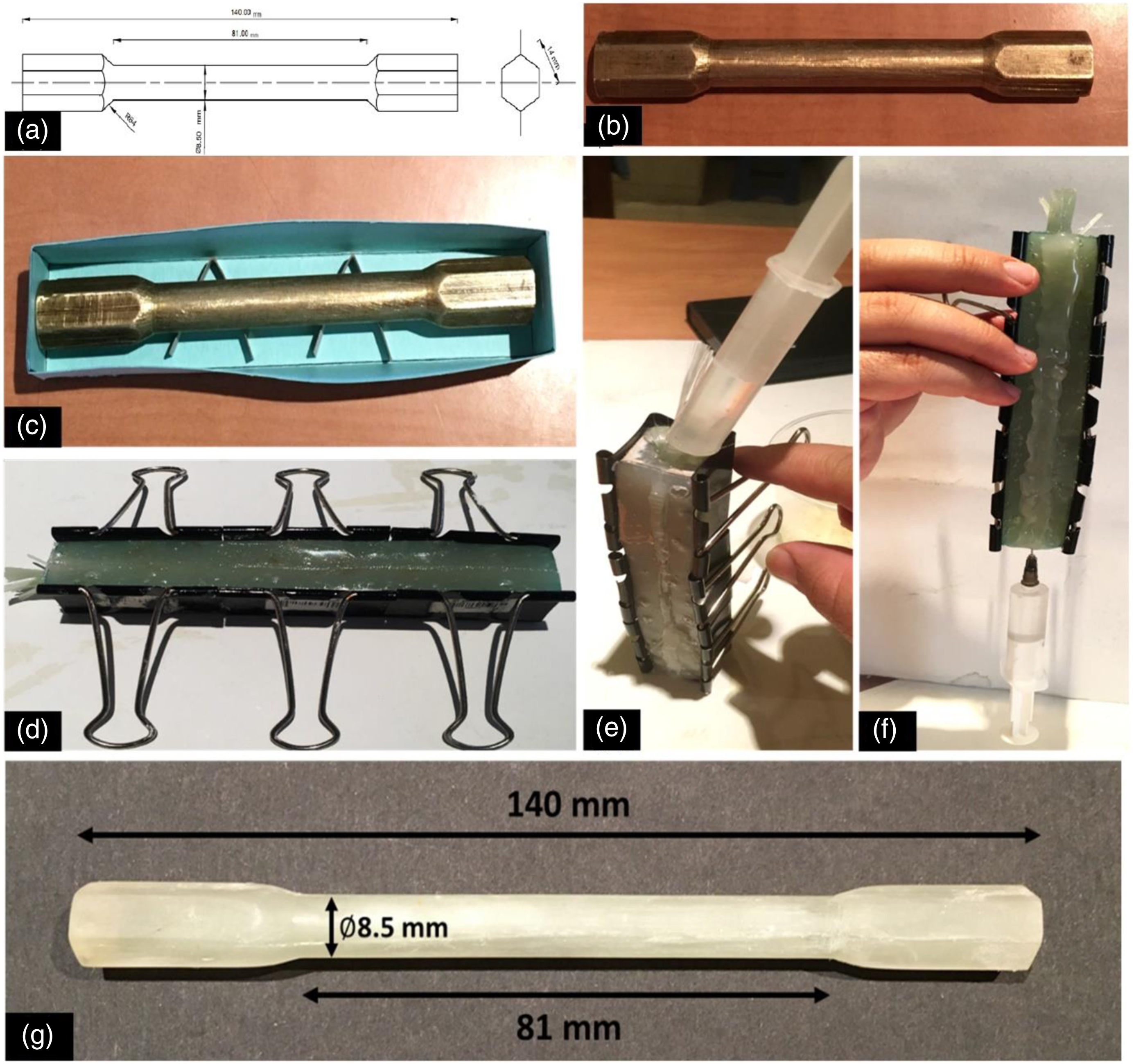

To calculate the physical characteristics of the composite, the following factors must be noted: weight percentage of the fibers and matrix, composite density and the volume of holes or voids created in the composite during the manufacturing process. All these factors could affect the mechanical strength and performance of the components under different loading conditions.
To calculate the FVF of the textile reinforced composite samples regardless of the void content, equation (1) was employed, as follows
It is necessary to determine the density of the composite to calculate and evaluate 
Also, in terms of volume, the theoretical density of the composite is as represented in equation (3):

Physical properties of the glass/epoxy composites.

The order of the numbers in parentheses is CV%, CV: coefficient of variation.

FESEM micrograph from the cross-section of the composite rod.
Torsional test
The torsional test was performed on the samples of NC3DOW and the Braid-pultruded Glass/epoxy composite using a SANTAM (STW-300E) pure torsion test machine with a 300 Nm load cell at the velocity of 30 rev/min (Figure 4), for each sample code, five specimens were produced to conduct the torsion test, according to ASTM E2207 and ASTM F383. SANTAM (STW-300E).
Multi-scale finite element modeling
The implementation of finite element modeling required the geometry of the unit cell to be created. A meso-geometrical model of the 3D fabric was used according to Minapoor et al. [35]. The unit cells of the two fabric preforms are shown in Figure 5. A unit cell of the non-crimp 3D orthogonal structure: (a) low yarn density, and (b) high yarn density.
During the composite production process, the yarn was impregnated with resin. Impregnated yarns were assumed as a unidirectional composite with an FVF equal to the packing density of the yarn

The micromechanical model, as developed by Chamis [33], was used to calculate the elastic constants of a transversely isotropic unidirectional composite, according to equations (7)–(12).


Elastic constants of the yarn impregnated with resin.
The NC3DOW fabric was embedded in the epoxy resin. The composite unit cell included the matrix and the 3D reinforcement, as shown in Figure 6. To determine the elastic constants of the composite, the periodic boundary conditions were applied to the unit cell. The applied load can be seen in Figure 7. The 3D reinforcement embedded in the matrix. Periodic boundary conditions: (a) tensile load and (b) shear load.

C3D8R element type in the ABAQUS/Standard element library, which is an 8-node linear, was applied for meshing the model. A total number of 20,112 elements were used for the meshing of the composite with the high yarn density. In this study, the yarns and matrix meshed separately. The embedded constraint was used to determine the interface between yarns and the matrix. The unit cell after the meshing process is shown in Figure 8(a). It should be noted that a mesh dependency study was performed on the model to ensure that the results were independent of the mesh size. Mesh generation: (a) Mesh generation of the unit cell, (b) The FE macro model of the composite rod.
To simulate the tensile behavior of the composites, their mechanical properties should be obtained from the meso-scale to use them in the macro-scale. According to equations (13)–(15), the mechanical constants of the stiffness matrix could be obtained by calculating the average volume stress and strain [36]


Results and discussion
Experimental results
One of the methods used to determine the shear mechanical behavior of isotropic materials is the torsion test. Using the torsional tests, the shear modulus and ultimate shear stress of NC3DOW and Braid-Pultruded glass/epoxy composites could be investigated. As said before, in the torsion machine, the rotational motion is applied to the composite sample on one side and the other is kept fixed. In this way, the sample is loaded by a torsional torque. The rotational motion is applied slowly to ensure the applied quasi-static loading rate. Figure 9 shows the details of the damage and destruction of the test samples during the torsion test. The composite shafts were broken along the direction of the yarns. The 15° crack was short, and the section gradually expanded diagonally in the thickness direction. Although the matrix failed, the fabric was not wholly broken. The sample was ruptured along the 45° direction, losing strength; however, it was not torn completely. This observation showed reinforcing fabrics, especially the non-crimp three-dimensional orthogonal fabric, had good resistance to the applied torque due to the interference and placement angle of the X and Y yarns to the Z-axis ones. Photograph the torsional fracture of glass/epoxy composite samples: (a) sample and grips, (b) initial break, (c) Tolerance of reinforced fabric against torsion, and (d) ultimate break.
The applied torque and shear strain were also monitored using digital instruments. The Torque/angle of the twist curve for each sample and matrix is presented in Figure 10. Torsional properties of the Glass/epoxy composite samples are shown in Table 6. Due to the specific nature of the composites during the torsion test, the results are expressed in both initial (peak) and ultimate (break) failure stages. Torque/Angel of twist for the specimens under torsional loading. Torsional properties of the glass/epoxy composite samples. The order of the numbers in parentheses is CV%, CV: coefficient of variation.

According to the diagrams and results obtained, as can be seen, the Torque/angle of the twist diagram initially moved with a steep slope, which was due to the presence of a brittle and rigid matrix in the composite structure. Also, it could be concluded that the initial failure was related to the matrix, and the torque was continued until the composite was broken ultimately. It was also observed that the ultimate fracture occurred in the middle of the specimen, as investigated by Potluri et al. and He et al. [22]. So, it could be supposed that the fibers along the 45° axis tolerated the most stress. By comparing the diagram and table of values, it could be concluded that the torque for the fracture of the matrix in each composite sample was almost the same. Still, it was more than the pure resin’s value, thus indicating the role of the reinforcing yarns. So, the resin tolerated more torque, thereby increasing the shear stress tolerance. In the specimens with reinforcing fibers, the applied torque was constant until the moment of the ultimate failure.
By increasing the FVF of the E-glass fabrics as shown in Table 4, the torque applied on the composite shaft was distributed in a more considerable amount of the fabric, ultimately leading to an increase in the shear stress and shear modulus of the composite, as investigated by Luo et al. [10]. Also, with a rise in FVF, the porosity rate of the composite shaft was decreased; so, the composite cohesion was improved, and the torque was distributed more evenly in the structure. Comparison of the samples showed that the NC3DOW-reinforced composite tolerated more torque than a similar braid-pultruded one due to the intrinsic cohesion of the fibers in the fabric and the presence of the straight yarns in the X and Y direction, merging them through the Z-long yarns. Another critical factor is the placement of X and Y diagonal yarns in the fabric structure at an angle close to 45°, causing the LD and HD composites to have higher shear stress and shear modulus than the BP composite. Specific torsion strengths of developed three structures considering volume fraction are respectively calculated 0.273, 0.275, 0.254 for LD, HD, and BP sample according to equation (16). It shows that NC3DOW-reinforced composite, due to the different structure and square cross-section, has more resistance to torsional torque.
In the case of NC3DOW, due to the square cross-section, the stress maintained during twisting is zero at the corners of the cross-section, so less stress is applied to the entire structure; however, in the braid-pultruded specimen, due to the circular cross-section, the stress concentration during twisting is on the perimeter of the structure, causing more stress on the composite, as investigated by Davalos et al. [18]. The elongation rate showed that low-density weaves (BP and NC3DOW LD) took more time to reach the breakpoint due to the more excellent elasticity of such fabrics, but the shear modules and energy to breakpoint were less. Also, comparing the HD and LD composite samples clearly showed that the stricter and denser structure of the HD texture increased the applied torque at the initial and final failure. The only advantage of the BP composite over HD and LD composites was the absolute angle of the twist and time to reach the final failure, which was due to the flexible structure of the braided fabric, as compared to the NC3DOW one.
In general, according to the results obtained, using the NC3DOW fabric on strengthening the properties of the epoxy matrix was demonstrated; this fabric could increase the fracture energy and shear strength of the epoxy matrix against the torsional torque. As shown in Figure 11, HD composite has the highest torque tolerance at high top twist-angles, highest shear modulus, and shear stress, So NC3DOW HD composite has the best torsional properties between the studied composite rods, so it can be an applicable option for use in industrial power transmission shafts that are under torsional force. Comparison of test results for the practical usefulness of composite.
FE Results
In this study, a unit cell of glass/epoxy composite rod reinforced by an NC3DOW fabric was modeled in the ABAQUS software. Periodic boundary conditions were applied to each unit cell for low and high yarn density. Figure 12 illustrates the stress contours of the matrix and the reinforcement part. Stress contours for the unit cell of the composite structure: (a) matrix and (b) non-crimp 3D orthogonal fabric.
Elastic constants of the composites from the FE model.

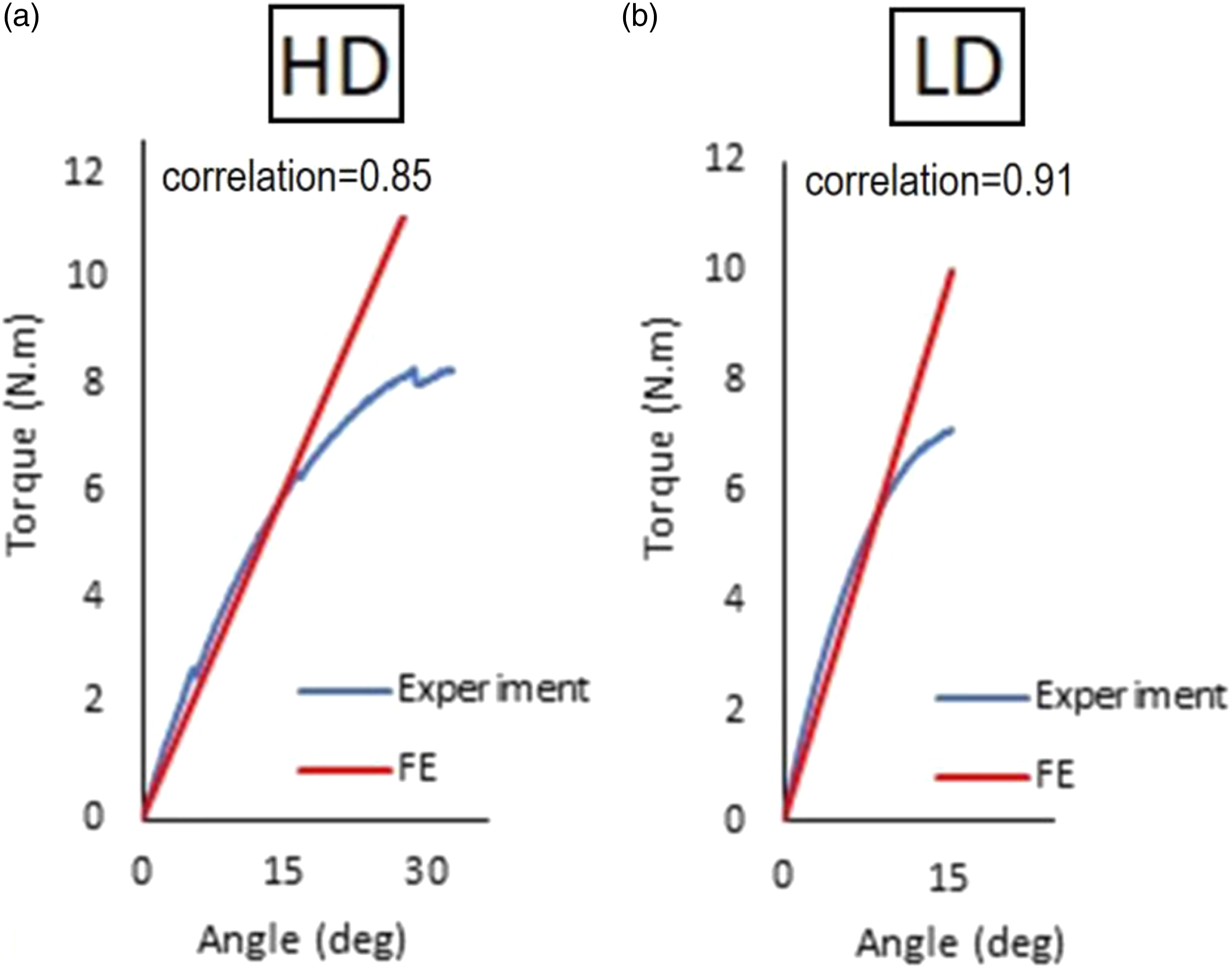
Torque/angle curves for FE and experimental results and correlation between them: (a) the composite with the high yarn density fabric and (b) the composite with the low yarn density fabric.
Conclusion
A 3D composite reinforced by the NC3DOW fabric is one of the novel research fields in composite studies. Due to shortcomings revealed in the detailed analysis of the composite’s torsional behavior, this article focused on the experimental and numerical investigation of this issue. Several 3D E-glass weaves, including low-density and high-density NC3DOW fabrics and also, braid-pultruded ones, were made to reinforce the epoxy resin. The glass/epoxy composite rods were subjected to torsional loading. It was observed that the composite rods were ruptured along the 45° direction and lost strength, but they were not torn completely. Reinforcing weaves, especially the NC3DOW fabric, led to good resistance to the applied torque due to the interference and placement angle of the X and Y fibers to the Z-axis yarns. The ultimate fracture occurred in the middle of the rod. It was also found that increasing the FVF of the E-glass structures led to the distribution of the torque in a more significant part of the fabric, thus increasing shear stress and shear modulus, as well as decreasing the void content rate of the composite rod. An NC3DOW-reinforced composite could, therefore, tolerate more torque than a similar braid-pultruded composite due to the intrinsic cohesion of the threads in the fabric and the presence of the straight yarns in the X and Y directions. The square cross-section of NC3DOW helped apply less stress to the entire structure. Also, using the NC3DOW fabric increased the fracture energy and shear strength of the epoxy matrix against the torsional torque. To simulate the torsional behavior of NC3DOW composites, a python code was developed in the FE software. A meso-geometrical model of the unit cell was used and embedded in the epoxy resin. The elastic constants of the composite were obtained from the meso-scale model and assigned to the macro-scale model. Based on multi-scale modeling results, the predicted mechanical constants of the NC3DOW glass/epoxy composites had a good agreement with the experimental results.
Footnotes
Acknowledgements
The authors gratefully acknowledge the financial support for this work that was provided by Isfahan University of Technology.
Declaration of conflicting interests
The author(s) declared no potential conflicts of interest with respect to the research, authorship, and/or publication of this article.
Funding
The author(s) received no financial support for the research, authorship, and/or publication of this article.