
Abstract
A meso-scale finite element model based on progressive damage was proposed to capture the failure and damage mechanisms of biaxial weft-knitted (BWK) composites. For this purpose, a suitable representative volume element of a BWK composite material was modeled. Then, appropriate boundary conditions were applied to simulate the uniaxial tensile test in the course and wale directions. Damage and failure mechanisms were predicted by developing a VUMAT user material subroutine based on the 3D Hashin criterion. To verify the numerical results, a comparison was made with the experimental data of Hessami et al. 1 It was found that the failure mechanisms of BWK composite are determined by the geometrical parameters of the BWK fabric. Based on the numerical assessments, some recommendations were made to fully exploit the potential of BWK composites as load-bearing structures. The numerical results provided new insights into the effect of the geometric parameters of BWK preforms on the composite failure mechanisms.
Introduction
Knitted fabrics, as reinforcement of polymer-based composites, exhibit high deformability, which, unlike woven fabrics, makes them appropriate for the fabrication of complex-shaped parts without the need for darts. 2 This advantage, resulting from the structure of interlocking yarn loops, allows the formation of a continuous reinforcement phase in complex-shaped composite parts. Although their in-plane mechanical properties are inferior to those of woven composites, they have been found to outperform woven composites in terms of energy absorption and post-damage properties. In general, there are two types of knitted fabrics: warp knitted and weft knitted. The former are made by knitting along the wale direction (longitudinal direction), while the latter are knitted along the course direction (horizontal direction).3,4 The inferior properties of knitted composites are caused by their highly looped architecture and low-volume fraction. 5 These shortcomings can be overcome through introducing weft and warp yarns within the knitted structure, which is known as biaxial weft-knitted (BWK) fabrics.3,6,7
Numerous experimental and numerical studies have been carried out on biaxial weft-knitted fabrics and their composites.1,3,6–18 A detailed review of the mechanical properties of biaxial weft-knitted fabrics and their fabrication methods was made by Hasani et al. 19 Demircan et al.3,12 investigated the tensile, flexural, and impact properties of BWK composites and also proposed a finite element model to predict the flexural modulus.
Xue and Hu fabricated BWK composites using flax yarns as weft and warp yarns and investigated their mechanical properties. 6 Demircan et al.13–16 also fabricated a thermoplastic BWK composite and investigated influencing parameters on mechanical behavior. Qi et al. 9 studied the tensile behavior of multilayer-bonded BWK (MBWK) composites. They also predicted the elastic properties of MBWK composites using finite element modeling on a representative volume element. The compressive properties of MBWK composites considering the influence of the number of plies and the fiber volume fraction were evaluated by Pei et al. 11 They employed carbon rovings as weft and warp yarns and polyester yarns as stitching yarns. Pham et al. 10 proposed two finite element models at different scales (macro-scale and meso-scale) to predict the mechanical response of BWK fabrics. Their aim was to simulate the forming process of BWK fabrics into complex-shaped composites. The effect of loop density on the tensile behavior of BWK composites was investigated by Hesami et al. 1 using experimental and numerical approaches. They proposed a meso-scale finite element modeling to predict the Young’s modulus along the wale and course directions. The strength of BWK composite parts was determined by including the Tsai-Wu failure criterion. Xiang et al. 7 employed BWK fabrics to fabricate composite helmet shells and characterized the post-induced deformations of the final composite part using 3D laser scanning technology. The tensile properties of BWK composites were studied by Shekarchizadeh et al. 8 along the course and wale directions. They also proposed meso-scale finite element modeling to predict the tensile stiffnesses in both directions and the most critical regions for damage initiation.
Overall, despite the considerable efforts made to experimentally evaluate BWK composites, no comprehensive finite element modeling has been used to simulate the damage evolution of BWK composites. Therefore, the present study aims to develop a three-dimensional progressive damage-based finite element model to capture the damage initiation and evolution of BWK composites. To this end, a user-defined mechanical material behavior (VUMAT) code was written based on available constitutive relationships for elastic domain, damage initiation, and evolution. The damage initiation and evolution were assessed using the three-dimensional Hashin criterion and the element weakening method, respectively. Our numerical results were compared and verified with the experimental results of Hessami et al. 1
Finite element modeling
Finite element modeling is known as a versatile technique for predicting the overall behavior and also the stress–strain fields over the entire component under certain boundary conditions. The increasing use of finite element modeling method stems from the development of computers which simplified the computational process. Diverse and user-friendly finite element based software such as ABAQUS, LS-DYNA, ANSYS etc. are available to the researchers and engineers to perform finite element analysis efficiently. Once a finite element model is verified and validated with experimental data, it can be used for further studies considering different boundary conditions, modification of associated parameters and materials. This is particularly important for expensive materials or those with higher manufacturing costs or a lengthy manufacturing process, for example, fiber reinforced composites. Hence, a suitable finite element model would lead to a reduction in costs and a saving in time.
Geometrical parameters of knitted fabrics for generating the RVE. 1


Elastic and strength values of BWK composite constituents from Ref. 1.

Fiber tension 


E and Flow diagram of subroutine VUMAT to model.


After defining and assigning the properties to the corresponding parts, appropriate orientations were defined for all composite yarns such that the local 1 direction was oriented along the fiber direction. Then, all parts were assembled as shown in Figure 1. Next, the embedded element technique was applied, considering the yarn parts as the embedded region and the matrix part as the host. However, to eliminate the volume redundancy caused by the embedded element technique,
20
the stiffness of the epoxy resin was subtracted from the stiffness matrix of the unidirectional composite yarns. For the failure and damage of the unidirectional composite yarns, the real stresses of the composite yarns were calculated using the stiffness matrix of the unidirectional composite yarns.
8
Furthermore, suitable boundary conditions were applied to simulate the tensile loading along the course and wale directions. 8-node linear brick elements with reduced integration and hourglass control (C3D8R) elements were employed to discretize the composite yarns with an element size of 0.1 mm and the matrix portion with an element size of 0.2 mm, as shown in Figure 3. Before the final finite element modeling was performed, the mesh dependency was checked. Thus, further refinement of the mesh size merely increases the computational cost without significantly improving the accuracy. All finite element models were performed using the dynamic explicit solver. It is worth mentioning that performing the simulation with the real displacement rate leads to disproportionately high computational costs. Therefore, the simulations were artificially accelerated by choosing the proper step time without defining a mass scale. This approach is common when performing finite element models with dynamic explicit solvers.31,32 The tensile response under the artificially accelerated simulation was verified by comparing the total internal energy with the total kinetic energy. To apply the boundary conditions, the macroscopic strain increment was applied to the unit cells by decomposing the displacement increment on the boundary into the macroscopically averaged displacement field and a period component that repeats from one unit cell to another, such as Discretized composite yarns and matrix part.


Moreover, based on the findings of several studies,34–37 it is likely that the round corners of knitted loops act as round-tip V-notches. Thus, they can cause stress concentrations. In order to accurately obtain the stress distribution around these notches, refined meshes were used for round corners of knitted loops, as shown in Figure 4. Therefore, the effect of the refined meshes for round corners of knitted loops on the failure mechanism was investigated. Refined mesh size on round corners of knitted loops.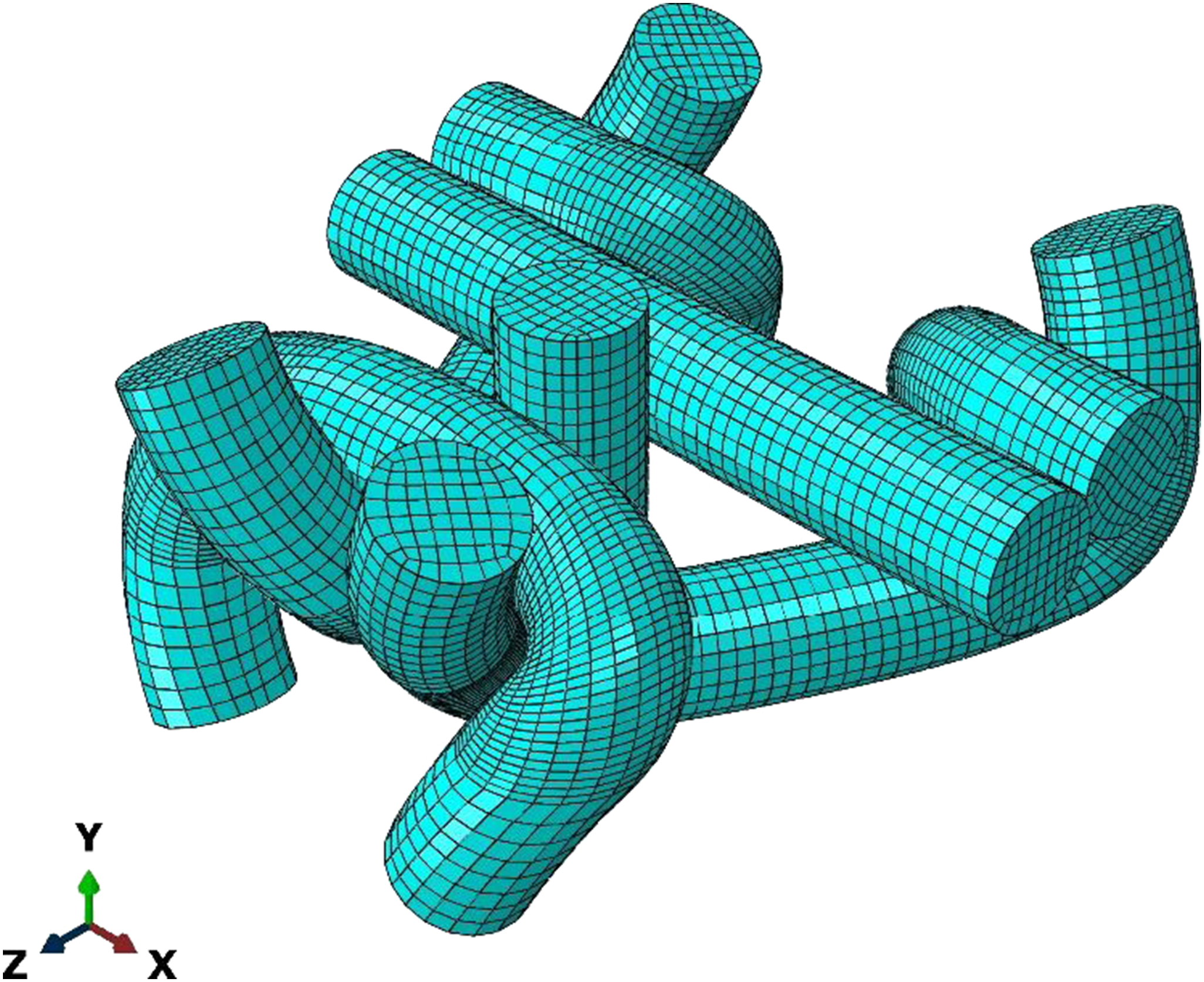
Results and discussion
In this study, the damage mechanism of the biaxial weft-knitted composites in wale and course directions was predicted by finite element method. In order to evaluate the findings of the proposed MSFE modeling, our results were compared with the experimental work of Hessami et al. 1 Hessami et al. 1 investigated the effect of loop density on the tensile behavior of BWK fabrics. In this regard, they produced three BWK fabric samples using high tenacity polyester fibers with different loop densities, as already listed in Table 1. Then, they fabricated BWK composite plates using epoxy resin through vacuum bag-assisted resin transfer molding. Finally, uniaxial tensile tests in accordance with ASTM D3039 were performed on BWK composites in course and wale directions.
Figure 5 shows the damage mechanism in course direction for all samples at different strains. According to Figure 5, when the composite is subjected to tensile loading in course direction, weft yarn, the foot of the loop, and head loop, which are the most aligned segments of RVE with the applied load direction, exhibit higher contribution against the applied load. However, the weft yarn resists higher loading compared to the foot of the loop and head loop. From the Figure 5, one can observe the damage initiation and its propagation within the BWK composite structure, that is, crack growth. All three samples, which differ in terms of wale and course density, exhibited similar failure mechanisms; however, there are few small discrepancies which will be discussed. That is, the crack initiates from the weft yarn and then propagates to the knitted loop. For samples K1 and K2, the crack propagates to the linking yarn and corner of the knitted loop; however, the damaged region of linking yarn of sample K1 is more obvious and wider than sample K2. Unlike samples K1 and K2, the crack propagates solely to the midsection of the head loop and barely to the linking yarn. Damage mechanism of BWK composite under tensile load in the course direction.
Moreover, it should be noted that BWK composite sample K1 failed at higher strain compared to other samples. The reason for this phenomenon is that the fiber volume fraction of sample K1 is higher than other samples. According to the work of Hessami et al., 1 the sample K1 has higher loop density, that is, higher wale and course density, as presented earlier in Table 1, which results in higher volume fraction of K1. This should be mentioned that knitted preforms suffer from low-volume fraction, 38 and this can be compensated through introducing non-crimp yarns in the course and wale directions. However, comparing the RVE dimensions of three BWK composite samples with different loop density (Table 1) show that there are lots of room for the formation of resin-rich pools. These resin-rich pools have adverse effect on the tensile performance of composite samples, since they are the main origins of crack formation due to their low elongation to break properties. This scenario is even worse for those samples with lesser loop density, that is, K2 and K3 samples. Therefore, BWK composite samples with lesser loop density (lower fiber volume fraction) fail at smaller deformations. On the other hand, since the reinforcement type being used in Hessami et al. 1 work is high tenacity polyester fiber, which is a high elongation to break fiber, increasing the fiber volume fraction results in a composite plate which can resist against the applied load at higher deformations.
The damage mechanism of BWK composite under tensile loading in wale direction is shown in Figure 6. As clearly can be observed from Figure 6, corners and legs of the knitted loop are the mostly aligned parts of the RVE in the applied load direction, and thus they yield higher loads whenever a BWK composite is under tensile loading in wale direction. Similarly, warp yarn resists higher loading in comparison to the corners and legs of knitted loop. Unlike course direction, one can observe that the crack growth in three samples differentiates from each other. That is, the damage initiated in sample K1 at the warp yarn at first Damage mechanism of BWK composite under tensile load in the wale direction.
The reason for this phenomenon is that increasing the loop density in the composite changes the geometry of the yarns that form knitted loops. In the composite with high loop density, the warp yarn is subjected to maximum normal stress, and lower shear stress is transferred to the loop leg. But as loop density decreases, legs of the knitted yarns become oriented and higher shear stress will be applied on. Therefore, they fail earlier than warp yarns. Figure 7 shows the shear stress distribution contour for all three samples. According to Figure 7, the maximum shear stress at the loop leg for K3 can be seen. This problem causes the loop leg to fail earlier than the warp for K3. Shear stress of BWK composites before failure initiation, (a) K1, (b) K2, and (c) K3.
In overall, the failure of knitted loop components is unfavorable earlier than the warp or weft yarns and must be considered when designing such composite structures as load-bearing structures. As a conclusion, it is highly recommended to produce BWK preforms with highest possible loop density. Increasing the loop density not only increases the fiber volume fraction, which has positive effect on the mechanical properties, but also reduces the length of loop leg, and warp yarns are the first to fail. Thus, increase in loop density results in the straight yarns (warp and weft) withstanding more stress than the other components, and after their failure, the knitted yarns play a reinforcing role in the composite material and result in higher elongation until the failure of the composite part.
Similar to the findings of tensile response in course direction, sample K1 fails at higher strain in comparison to other samples. As thoroughly discussed earlier for course direction, the superior tensile performance of sample K1 over other samples is resulted from its higher fiber volume fraction. Moreover, as was expected, the FE simulation findings showed that the fracture occurs due to the third fracture mode of the Hashin model, which is tensile failure of the matrix.
Our numerical results are in agreement with the numerical work of Hessami et al. 1 and Shekarchizadeh et al. 8 Using the Tsai-Wu criterion for all K1, K2, and K3 samples, 1 Hessami et al. predicted the most critical region for damage occurrence for the warp and weft threads in wale and course directions, respectively. However, by implementing the proposed progressive damage-based MSFE model, the failure mechanism was found to change with the variation of loop density, especially in wale direction. On the other hand, Shekarchizadeh et al. 8 reported in their work that the leg of the loop is the most critical region for damage initiation in wale direction, while weft thread is responsible for damage initiation in course direction. According to their reports on wale direction and findings of the current work, it can be assumed that the BWK preform used in the work of Shekarchizadeh et al. 8 had a low loop density since the leg of the loop was predicted as the first to fail in wale direction. However, what distinguishes the proposed MSFE model from previous models is the in-depth analysis which was performed numerically to decipher the failure mechanisms and crack growth within the BWK composite structure in relation to the effect of loop density.
Unlike other studies,1,3,8 the proposed MSFE model is capable of capturing the stress–strain diagram of BWK composite samples. Therefore, to evaluate the stress–strain curves extracted from the FE models, a comparison was made with the experimental results of Hessami et al.
1
The stress–strain curves obtained from the proposed MSFE mode and experimental results of Hessami et al.
1
are illustrated in Figure 8. Besides, calculated tensile properties of each are reported in Table 3. Stress–strain curves for numerical and experimental results in wale and course directions.
1
Comparison between the proposed MSFE and experimental results of Hessami et al.
1
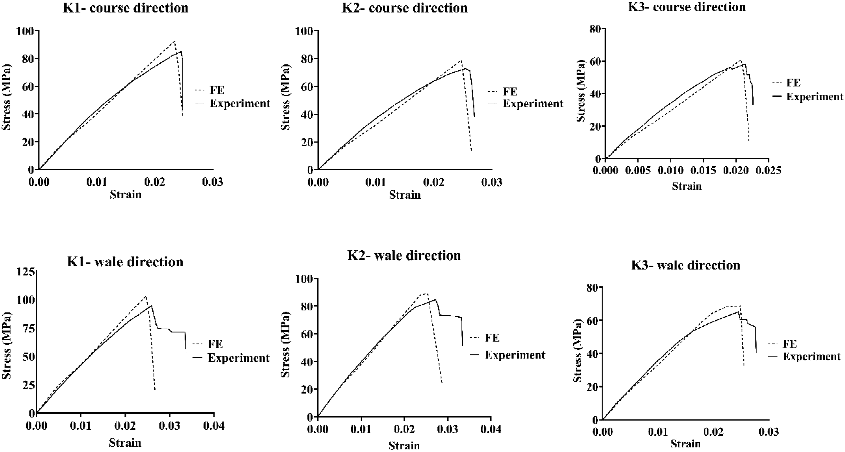

As can be seen, the numerical results have a very good agreement with the experimental results in the elastic region of the stress–strain curves. The deviation increases in the nonlinear section and at the failure point. According to Table 3, the error values are less than 20%, which shows that the proposed model can be used to predict the tensile strength of BWK composites in the course and wale directions. This should be pointed out that it is common that a finite element model to overestimate properties, especially tensile strength, since no defects were considered in the proposed MSFE model. While there are various forms of defect (i.e., void or craze) within the composites which are unavoidable and affect mostly the tensile strength. Induced damaged to the fiber due to knitting process 12 and also incompatibility of the modeled yarn cross-section with the actual yarn cross-section 8 could be another possible sources of error. Besides, according to Figure 8, the proposed MSFE model was incapable of predicting the nonlinear section of the BWK composite. This can be compensated through considering the yarn-to-yarn and yarn-to-matrix interactions through employing cohesive zone modeling. 39
As mentioned above, the stress concentration may be caused by the round corners of the knitted loops and affect the failure mechanism of BWK composites. In this regard, the corners of the knitted loops were refined as already shown in Figure 4, and the current MSFE model was performed on each sample in both directions, that is, course and wale. Figure 9 and Figure 10 show the results for the BWK composite with refined mesh at the corners of the knitted meshes for all samples in the course and wale directions, respectively. Although the refined mesh at the corners slightly affected the failure mechanism, for instance, sample K1 in course direction, similar failure mechanisms were obtained as in Figure 5 and Figure 6. It also had an insignificant effect on the tensile stress–strain diagrams. Damage mechanism of the BWK composite with refiner mesh under tensile load through the course direction. Damage mechanism of the BWK composite with refiner mesh under tensile load through the wale direction.

Overall, the in-depth numerical investigation of the tensile behavior and failure of BWK composites (stress contour plots) results in some recommendations below to make much more efficient use of this structure. First, based on the findings reported above, it is recommended to fabricate BWK preforms with high loop density. Since the loop density is limited by the yarn diameter and needle gauge of the knitting machine, it might be better to use finer yarns (yarns with smaller diameters) to achieve high loop density. Second, it is recommended to use fibers with high modulus and high strength as weft and warp yarns (e.g., carbon, glass, and basalt fibers) and fibers with high elongation at break and medium tensile modulus and strength as knitted stitches (Kevlar and UHMWPE fibers). The reason for this recommendation is the degradation process observed here. That is, the warp or weft yarns fail first when subjected to tensile stress in wale or course direction. Moreover, after the failure of the warp or weft yarns, the knitting yarns are responsible for withstanding the applied load. The use of fibers with a high elongation at break as knitting yarns therefore leads to further resistance of the BWK composite part to the applied load, that is, to an improvement in the toughness of the BWK composite.
Conclusion
A meso-scale finite element model based on the Hashin failure criterions was proposed herein to predict the tensile response of BWK composite. A user material subroutine code (VUMAT) was developed to consider the failure modes of fiber-reinforced polymer composites. Appropriate boundary conditions were applied on the representative volume element of BWK composite to simulate the uniaxial tensile loading in course and wale directions. To verify and validate the proposed model, a comparison was made with the experimental results of Hessami et al.
11
Following conclusions were made: 1. It was observed that geometric parameters (loop density and wale and course space) of BWK preform affect significantly the failure mechanisms and tensile properties of BWK composite in wale direction. 2. The knitted loops of BWK composites with low loop density (higher wale and course space) fail in advance to the failure of warp thread, when tensile load is applied in wale direction. This reduces the tensile strength and failure strain of BWK composite in wale direction. 3. Based on the numerical observations, it is highly recommended to produce BWK preforms with highest possible loop density. This not only increases the fiber volume fraction of final composite part but also the warp yarns are the first to fail and enhances the tensile properties of BWK composite. 4. Unlike other studies which only predicted the elastic regions, the developed VUMAT code was capable of predicting the tensile strength and stress–strain diagrams of BWK composite in course and wale directions successfully. Moreover, the crack initiation and growth within the RVE of BWK composite were observed.
Footnotes
Declaration of conflicting interests
The author(s) declared no potential conflicts of interest with respect to the research, authorship, and/or publication of this article.
Funding
The author(s) received no financial support for the research, authorship, and/or publication of this article.