
Abstract
Centrifugal spinning is a fast and safe nanofiber production technique and polyacrylonitrile (PAN) nanofibers have been widely studied for many applications including energy storage, filtration, sensors, and biomedical applications. Nanofiber morphology, specific surface area, porosity and average fiber diameter are important to determine the performance of nanofibers in these fields. In centrifugal spinning, nanofiber morphology and average fiber diameter are influenced by solution properties and process parameters including rotational speed, feeding rate, collector distance, and nozzle diameter. In this study, the effect of solution concentration, rotational speed, feeding rate, collector distance and nozzle diameter on average fiber diameter and fiber morphology were studied and statistical analysis was performed to determine the main factors. Optimum solution and process parameters were determined as well. Increased average fiber diameter was seen with increasing polymer concentration and nanofibers produced at 4000 rpm with the feeding rate of 60 ml/h had the lowest average fiber diameter for all studied nozzle sizes (0.3 mm, 0.5 mm and 0.8 mm). 8 wt. % PAN solution was centrifugally spun with the rotational speed of 4000 rpm, feeding rate of 60 ml/h, collector distance of 20 cm and nozzle diameter of 0.3 mm and bead free nanofibers with the average fiber diameter of 680 ± 87 nm was observed.
Introduction
Nanofibers have been widely studied owing to their merits of high specific surface area and highly porous interconnected 3 D structure. Nanofibers exhibit several excellent characteristics such as large surface area to volume ratio, adjustable surface properties, high pore volume, small pore size and high mechanical performance compared to the conventional fibers [1,2]. Thus, nanofibers have been investigated in many fields including but not limited to energy storage, filtration, sensors and biomedical applications [3–6]. In energy storage, nanofibers have improved the electrochemical performance owing to high specific surface area and improved conductivity [7]. In fuel cell applications, nanofibers exhibited excellent chemical, thermal stabilities and mechanical strength compared to conventional electrolyte membranes [8]. For solar cell applications, higher specific surface area led to larger pores thus converted more light into electric current [9]. In filtration applications, nanofibers offer high filtration efficiency due to large specific surface area [10,11]. In addition, long term filtration performance could be achieved with the porous nanofiber morphology [2]. High specific surface area and short diffusion passage length of nanofibers are beneficial in drug delivery mechanisms of several drugs including antibiotics [12] and anticancer drugs [13]. In cosmetic applications, skin masks made of nanofiber membranes possess high surface area that offers fast transfer rate of the additives to the skin for fast healing [1]. In protective textiles, polymer nanofibers provide an enhanced contact between the protective clothing and dangerous environment due to their large surface area [14].
Electrospinning is the most commonly used technique to produce nanofibers. However, this technique suffers from very slow production rate, high consumption of organic solvents and high risk of fire. Centrifugal spinning offers fast and safe method to produce nanofibers and the production rate is at least two orders of magnitude higher than electrospinning [15–17]. In this technique, centrifugal force is used to produce nanofibers. Centrifugal force is employed on viscous polymer solution or melt. When the angular velocity is larger than the critical velocity, which is the minimum speed to overcome the surface tension and viscosity of the solution, the solution will eject out as a jet from the nozzles. The jet moves along a sharp curvature path after exiting from the nozzles while solvent evaporates. The jet continues to move forward and bends until the solvent completely evaporates, fiber solidifies and reaches to the collectors. In this technique, solution properties mainly concentration and process parameters including rotational speed, feeding rate, collector distance, nozzle diameter affect fiber formation, morphology and average fiber diameter [18–21]. Besides being a fast and safe technique, larger spectrum of materials could be centrifugally spun without using salts or additives compared to electrospinning and thus centrifugal spinning can be used in many fields [4,5]. The advantages of centrifugal spinning over electrospinning have been reported in nanofiber applications. Rihova et al. [22] compared electrospun and centrifugally spun PVA and PVP nanofibers and found out that electrospinning yielded planar 2 D layers of fibers whereas centrifugal spinning yielded bulky 3 D structures. Moreover, the viscosity range of the studied polymers were broader with centrifugal spinning compared to that of electrospinning. At high viscosity, centrifugal spinning led to fiber formation whereas electrospinning did not. In addition, spinning solutions were completely used in centrifugal spinning whereas 20-30% of the spinning solution was wasted in electrospinning [22]. Centrifugal spun nanofiber provides a 3 D porous structure which is advantageous in various nanofiber applications compared to electrospinning. Hou et al. produced highly porous ethyl cellulose/PVP fibers with centrifugal spinning but porous structure was not seen in electrospun EC/PVP nanofibers [23]. Liu et al. [24] regenerated silk fibroin nanofibers with electrospinning and centrifugal spinning under the same conditions and centrifugally spun nanofibers enhanced the structural stabilities and thermostabilities compared to the electrospun nanofibers [24]. Vocetkova et al. [25] compared PCL nanofiber scaffolds prepared with electrospinning and centrifugal spinning. The centrifugally spun scaffolds enabled more deep cell penetration compared to the limited cell infiltration of the electrospun scaffolds [25].
PAN has high thermal, chemical and mechanical stability. Thus, PAN and copolymers of PAN have been studied excessively in diverse applications such as separators [26–31], filtration [32–35], textile applications [36–39], sensors [40–43], drug delivery [44,45] and wound dressing [46,47]. Salussoglia et al. [32] used PAN nanofibers to investigate the usage of a vacuum collection system in aerosol filtration applications and resulted that PAN nanofibers enhanced the collection efficiency and pressure drop owing to its superficial porosity and small fiber diameter. Hashmi et al. [36] used electrospun copper oxide loaded PAN nanofibers membranes for antimicrobial breath mask applications and observed excellent morphological, mechanical and antimicrobial properties owing to the uniform and smooth nanofibers. Liu et al. [40] fabricated a fast response ammonia sensor based on electrospun PPy-PAN nanofiber yarn which had exhibited an excellent sensing properties with a response time less than 1 second due to high surface area of the nanofiber. Kharaghani et al. [44] used electrospun PVA/PAN nanofibers for drug delivery and observed a promising dual-drug carrier system with high biocompatibility since nanofiber had porous core-shell structure. In the field of wound dressing, Homaeigohar et al. [46] fabricated electrospun PAN biohybrid nanofibers coated with a hydroxyapatite shell which showed promising cellular bioactivity due to high mechanical characteristics of the nanofiber.
Even any material with a carbon backbone can be used as a precursor for carbon materials, PAN is the most commonly used carbon precursor due to its high carbon yield up to 56%, flexibility for maintaining the structure, excellent mechanical and electrochemical properties [48,49]. PAN based carbon nanofibers have been used in many fields including electrodes [50–56], supercapacitors [57–63], fuel cells [64–67], sensors [68–72], solar cells [73–75], biomedical applications [76] and tissue engineering applications [77–81]. For instance, Kumar et al. [50] used carbon nanofiber from electrospun PAN precursor for anode material for lithium ion batteries which showed high initial discharge capacity of 826 mAh g−1 at 200 mA g−1. Abeykoon et al. [57] increased the supercapacitor performance with a high capacitance of 140 F g−1 by using carbon nanofiber derived from electrospun PAN/PMMA polymer blend with a high surface area of 2419 m2 g−1. Ghasemi et al. [66] used electrospun PAN precursor for CNF/Nafion nanocomposite membranes for microbial fuel cell systems which produced a highest voltage of 57.64 mW m−2 whereas pure Nafion produced 13.99 mW m−2 voltage. In case of sensor applications, Cheng et al. [68] produced n and p doped carbon nanofibers with electrospinning that had a high sensitivity, low detection limit, wide detection range and good electrocatalytic activity determination. Cho et al. [69] fabricated a rapid and efficient electrochemical iodine sensor based on electrospun PAN based carbon nanofiber and exhibited a high detection selectivity of iodine even in the presence of both interfering agents and high salt concentrations. Elbohy et al. [73] used graphene embedded PAN based carbon nanofiber with electrospinning method as a high efficiency dye sensitized solar cell and observed an improved energy conversion efficiency from ∼8.63% to ∼9.70%. PAN based carbon are also chosen for biomedical applications due to their high specific surface area and porosity. Liu et al. [76] produced electrospun PAN based carbon nanofibers containing b-tricalcium phosphate nanoparticles and the resulting CNFs had good biocompatibility, favored cell growth and improved the degradation properties. Zhang et al. [77] fabricated electrospun PAN/PMMA blend carbon precursor with bioactive glass composite carbon nanofiber for skeletal tissue regeneration. Owing to the nanoporous structure of CNF, the interfacial reaction area and bioactivity was enhanced [77].
The morphology and fiber diameter affect the performance of the PAN nanofibers as well as PAN based carbon nanofibers. For example, PAN nanofiber mats with average fiber diameter of 224 nm was produced with electrospinning and increased filtration performance and enhanced filter quality was reported compared to conventional HEPA filter [11]. In another study, average fiber diameter of PAN nanofibers produced with electrospinning containing 1% copper oxide was as small as 197 nm which improved the tensile strength of the nanofibers when used in breath mask applications [36]. Adabi et al. [82] reported that the fiber diameter of electrospun PAN based CNF directly affected the conductivity and cyclic voltammetric response in electrochemical sensors and biosensors. When the average fiber diameter of PAN based CNF was lower than 75 nm and higher than 80 nm, the cyclic voltammetric response and conductivity was decreased whereas when fiber diameter was in-between 75-80 nm, CNF can be used directly as nano electrode with good performance [82]. Electrospun PAN based nanofiber with an average diameter of 350 nm was used as a separator for lithium ion batteries and exhibited superior rate capability and cycling [27]. Similarly, electrospun PAN based carbon nanofibers with a diameter of 250 to 380 nm was used as a separator for lithium ion batteries and exhibited better cycling stability, rate capability compared to conventional materials due to the smaller fiber diameter, homogeneous pore distribution and high porosity [30]. Sabetzadeh et al. [29] produced electrospun porous PAN nanofiber membrane with a specific surface area of 52 m2 g−1 and an average fiber diameter range of 700-800 nm. On the other hand, electrospun nonporous PAN nanofiber membrane was produced under the same conditions with same diameter range that had a specific surface area of 16.2 m2 g−1. When both membranes were used as a separator for lithium ion battery, the porous nanofiber had the greatest ionic conductivity due to the high interconnected porosity and high electrolyte uptake [29].
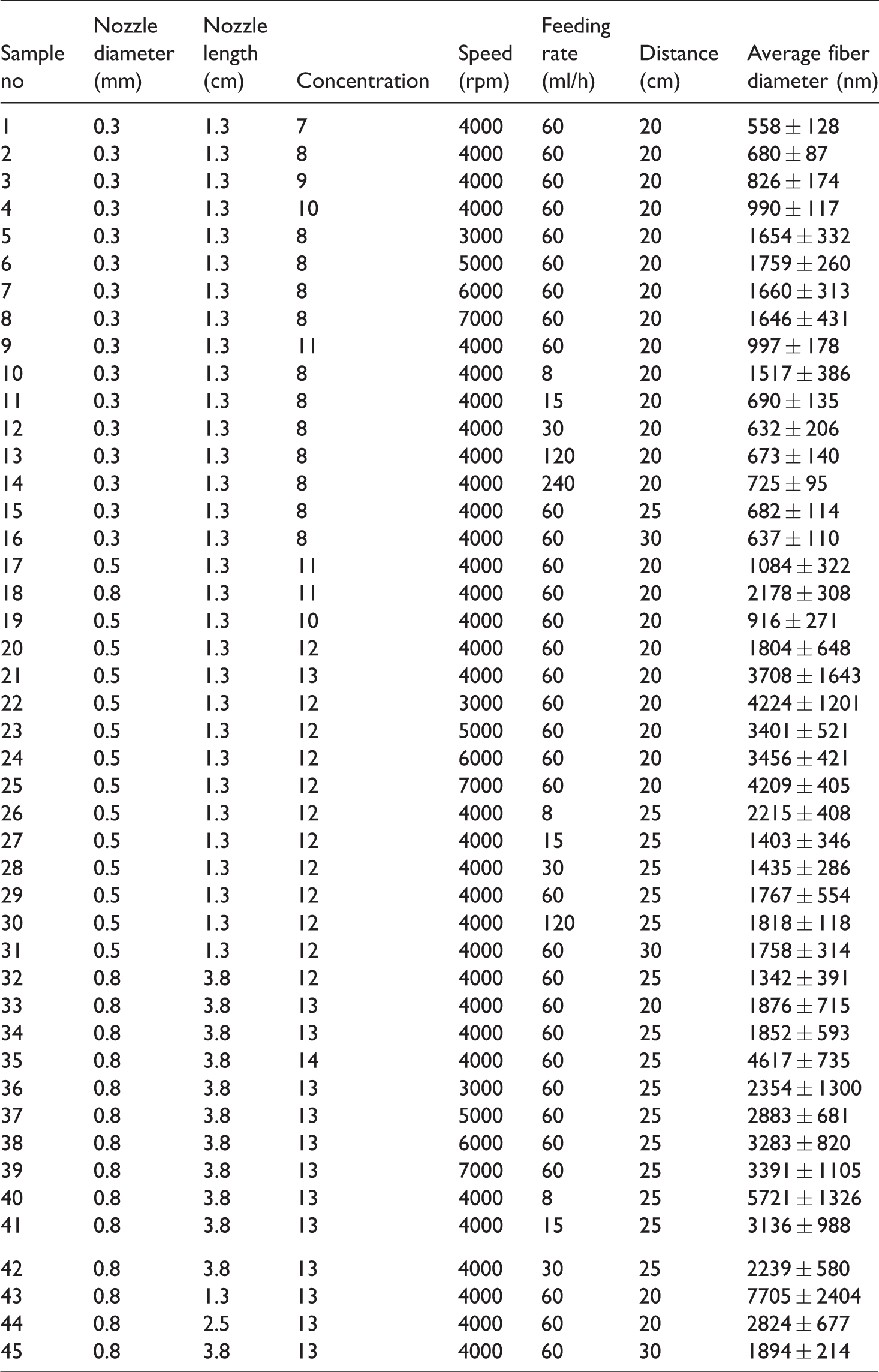
So far, polystyrene [83], poly(methyl methacrylate) [84], poly(ethylene terephthalate) [85], polyvinylpyrrolidone [86], polylactic acid [87,88], polyamide 6 [15], polyvinyl acetate [89,90], poly(ethylene oxide) [3,91], polycaprolactone [92,93], polyvinylidene fluoride [4], poly(3-hydroxybutyrate-co-3-hydroxyvalerate) [94] were centrifugally spun however studies reported so far had limited number of parameter with few data points and there is no comprehensive parameter study with detailed experimental design that shows effects of all solution and process parameters on fiber morphology. As reported in a recent review on centrifugally spun nanofibers [95], there were not a systematic parameter study that includes all solution and process parameters of centrifugal spinning including concentration, rotational speed, feeding rate, collector distance and nozzle diameter. PAN is an important material for many application areas. Therefore, considering the advantages of centrifugal spinning, fast and safe nanofiber production technique, studying all process and solution parameters which affect performance of PAN nanofibers is important for future researches. Moreover, fiber morphology and diameter affect porosity, surface area, functionality and performance [55,89,96]. Considering the importance of average fiber diameter and morphology, comprehensive parameter study along with statistical analysis is vital. In this study, centrifugally spun PAN nanofibers were fabricated and effect of solution and process parameters on fiber morphology and average fiber diameter was studied. All process parameters of centrifugal spinning as well as solution parameters were studied in large range for the first time. Table 1 shows all studied solution and process parameters with the values studied. Statistical analysis was also reported to determine the important factors. It was seen that polymer concentration and nozzle diameter was main factors to determine the morphology and average fiber diameter. Effect of solution concentration was investigated by preparing different polymer concentrations (7-13 wt. %) and centrifugally spun these solutions by using three different nozzle diameters (0.3 mm, 0.5 mm and 0.8 mm). Larger average fiber diameter was observed with increasing polymer concentration for all studied nozzle diameters. Wide rotational speed range, from 3000 rpm to 7000 rpm, was also studied and the lowest average fiber diameter was observed when the rotational speed was 4000 rpm for all nozzle diameters studied. 8 wt. % PAN solution was centrifugally spun with the rotational speed of 4000 rpm, feeding rate of 60 ml/h, collector distance of 20 cm and nozzle diameter of 0.3 mm and bead free nanofibers with the average fiber diameter of 680 ± 87 nm was observed.
Solution and process parameters.

Experimental
Chemicals
Polyacrylonitrile (PAN, Mw = 1,50,000) and N,N -dimethyl formamide (DMF) were supplied from Sigma Aldrich.
Centrifugal spinning of Polyacrylonitrile nanofibers
PAN solutions with different concentrations (7-13 wt. %) were prepared in dimethylformamide (DMF) and stirred for 24 hours at ambient temperature. PAN solutions were then centrifugally spun into nanofibers with the solution and process parameters listed in Table 1. The centrifugal spinning system (Figure 1) was powered by a DC motor and the rotational speed that applied in the range of 3000 – 7000 rpm was controlled by a speed control module. The cylindrical rotating disk was fixed on a shaft, which was controlled by the motor. The polymer solution was continuously fed into the spinneret by a syringe pump system and the feeding rate varied in the range of 8-240 ml/h. The fibers were collected on aluminum rods that were located on a circular pattern around the spinneret with three different adjustable distances, 20, 25 and 30 cm.

Schematic view of the centrifugal spinning.
Structure characterization
The morphology of PAN nanofibers was investigated by FEI Quanta FEG 250 scanning electron microscope and Hitachi HighTech HT7700 tunneling electron microscope. Diameters of nanofibers were measured by using Revolution 1.6.0 analysis software. At least 100 fiber diameters were measured on SEM images and average of them reported in Table 2. Viscosity measurements were performed using a programmable rheometer (The Brookfield DV-III Ultra) at room temperature with Brookfield software; Rheocalc V2.3. The surface tension measurements were performed using a tensiometer (Dataphysics DCAT 11EC, Germany) by the Wilhelmy plate method at room temperature. Minitab 16 was used for ANOVA analysis.
Average fiber diameter for centrifugally spun PAN nanofibers.
Results and discussion
Solution viscosity and surface tension
Viscosity is the most effective factor for fiber formation and solution concentration directly influences the viscosity of the spinning solution. Viscous force is the liquid’s resistance to flow thus viscosity can prevent the shape of the polymer jet to be altered quickly. High viscosity could prevent jet formation due to lack of centrifugal force whereas low viscosity leads to jet breaking and thus formation of beads instead of fibers [97]. In order to study the effect of concentration on fiber formation and average fiber diameter, 7-13 wt.% PAN solutions were prepared in DMF and solution viscosities were reported for all studied concentrations in Table S1. As seen from the table, after 7 wt. % solution concentration, the viscosity increased significantly with increasing concentration. The viscosity was 165 mPa s for 7 wt.% solution concentration and increased up to 3140 mPa s when the solution concentration was 13 wt.%. A critical concentration must be exceeded in order to produce nanofibers in centrifugal spinning system. Below critical concentration beads or beaded fibers form whereas nanofibers form without beads after critical concentration. Increasing solution viscosity with polymer concentration is shown in Figure 2 and critical concentration was found to be 7%.
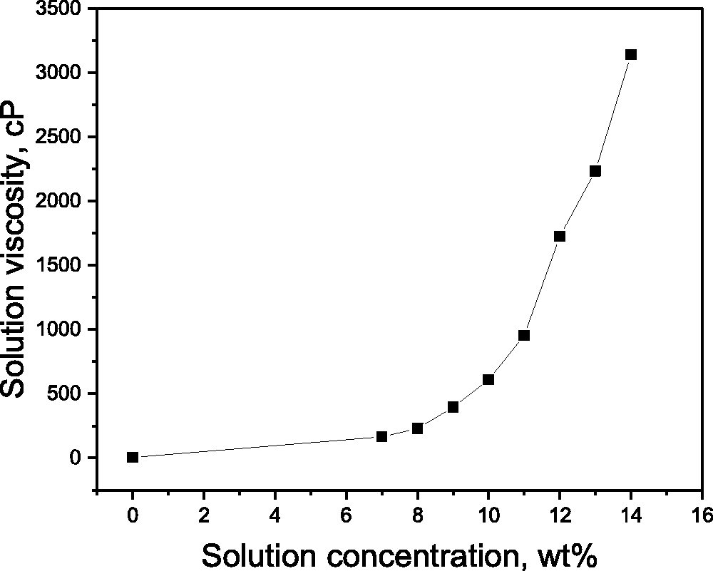
Solution viscosity versus polymer concentration.
Surface tension of polymer solution is a critical parameter in centrifugal spinning. Surface tension is a physical force that rises as a result of the atoms of the liquid pulling each other in all directions and depends on the nature of the liquid. Liquids which have large intermolecular forces have a large surface tension. Surface tension makes the jet surface area shrink and centrifugal force must overcome the surface tension for jet formation [97]. During centrifugal spinning, the polymer jet is stretched and the surface area is expanded with the centrifugal force. If the surface tension is too high and the centrifugal force is not enough, the polymer solution will not exit through the nozzles. This can lead to clogging in the nozzles or breakage of the polymer jets; thus, beads can form instead of fibers. Surface tension was listed in Table S1 for different polymer concentration. Surface tension is mainly affected by the composition of solvents [98]. Since only DMF was used; it was seen that polymer concentration did not affect the surface tension significantly, which was around 37 mN/m for all studied polymer concentrations (7-13 wt.%). Similarly, same surface tension with varying polymer concentrations was reported for other polymer solutions including chitosan and PEO [6]. When chitosan:PEO solution was prepared with different mass ratios (100:0 to 0:100) at a total of 4% concentration in distilled water and alginate solution (3%), the surface tension remained nearly unchanged regardless of the blend ratio with a value of ∼65 mN/m [6]. Okutan et al. [99] used two different gelatin concentration in acetic acid and surface tension remained almost same for 7% and 20% gelatin concentration, respectively. In another study, Ramakrishnan et al. [100] reported that 2.5% and 5% PEO in distilled water had a surface tension of 62.18 and 61.45 mN/m which showed that increasing concentration had no significant change on the surface tension.
Solution concentration
Figure 1 shows the schematic view of centrifugal spinning. In this technique, centrifugal force is applied to the spinning solution and fiber formation is achieved when the centrifugal force overcomes the surface tension and viscous forces. The spinnability is related to viscoelastic behavior of solution and some chain overlap and entanglements are needed for fiber formation. Solution concentration and thus viscosity is very important to determine the morphology and average fiber diameter. When the solution concentration is too low, there is not sufficient chain overlap to form continuous jet and droplets are seen on the collectors. High amount of entanglements improves spinability at high concentrations however higher concentration results in larger viscosities and larger stress relaxation time and restrict jet stretching and thinning that leads to larger average fiber diameter [15,21].
Figures 3, S1 and S2 shows the effect of different concentrations on the morphology and average fiber diameter for different nozzle diameters of 0.3 mm, 0.5 mm and 0.8 mm, respectively. When the nozzle size of 0.3 mm was used, fiber formation was seen for the concentrations of 7, 8, 9, and 10 wt.%. When concentration was lower than the critical concentration, 7 wt. %, no fiber formation was observed. The average fiber diameter was 558 nm, 680 nm, 826 nm and 990 nm for the concentrations of 7, 8, 9, and 10 wt. %, respectively. Some large bead formation was observed when 7 wt.% solution was used to produce PAN nanofibers however bead free nanofibers was observed when the polymer solutions with 8, 9, and 10 wt.% concentration was used. In another study, the average fiber diameter was also increased with increasing polymer concentrations for PVDF fibers [4].18, 21.5 and 25 wt% PVDF solutions in DMF were forcespun at 4000 rpm and average fiber diameter was 340, 900 and 1242 nm, respectively. Higher concentrations resulted in larger fiber diameters but also had higher bead formation [4]. Merchiers et al. [101] centrifugally spun PS solution to obtain nanofibers. Increasing the concentration from 10 to 25 wt% resulted in higher average fiber diameter; from 0.52 to 10.05 µm, respectively [101]. Similarly, Xia et al. [20] produced centrifugally spun FeCl3/PVP nanofibers and average fiber diameter was 2437, 2571, 2699 and 2645 nm for concentrations of 9, 11, 13 and 17 wt%, respectively due to the increasing viscosity of the solution. With increasing concentration, solution viscosity increases, thus the average fiber diameter increases [20].

SEM images of centrifugally spun PAN nanofibers produced by using 7, 8, 9, 10% PAN concentrations. Nozzle diameter: 0.3 mm, rotational speed: 4000 rpm.
Furthermore, smaller nozzle diameter improves fiber formation at lower concentrations. When the nozzle size of 0.3 mm was used, fibers were observed at the concentrations of 7 wt % to 10 wt.%. However, no fiber formation was observed below 10 wt.% and 12 wt. %, respectively, when the nozzle diameter of 0.5 and 0.8 mm was used. This proves that lower spinnable concentration threshold could be affected by applied shear stresses [15].
When the nozzle size of 0.5 mm was used, the average fiber diameter was observed as 916 nm, 1084 nm and 1804 nm, respectively, for the concentrations of 10, 11, and 12 wt.%. Similarly, when the nozzle with the size of 0.8 mm was used, the average fiber diameter was increased as the concentration increased. For 12, 13, and 14 wt.% concentrations, the average fiber diameter was 1342 nm, 1852 nm and 4617 nm, respectively. Average fiber diameter with increasing concentration for all nozzle diameters could be also seen in Figure 4.
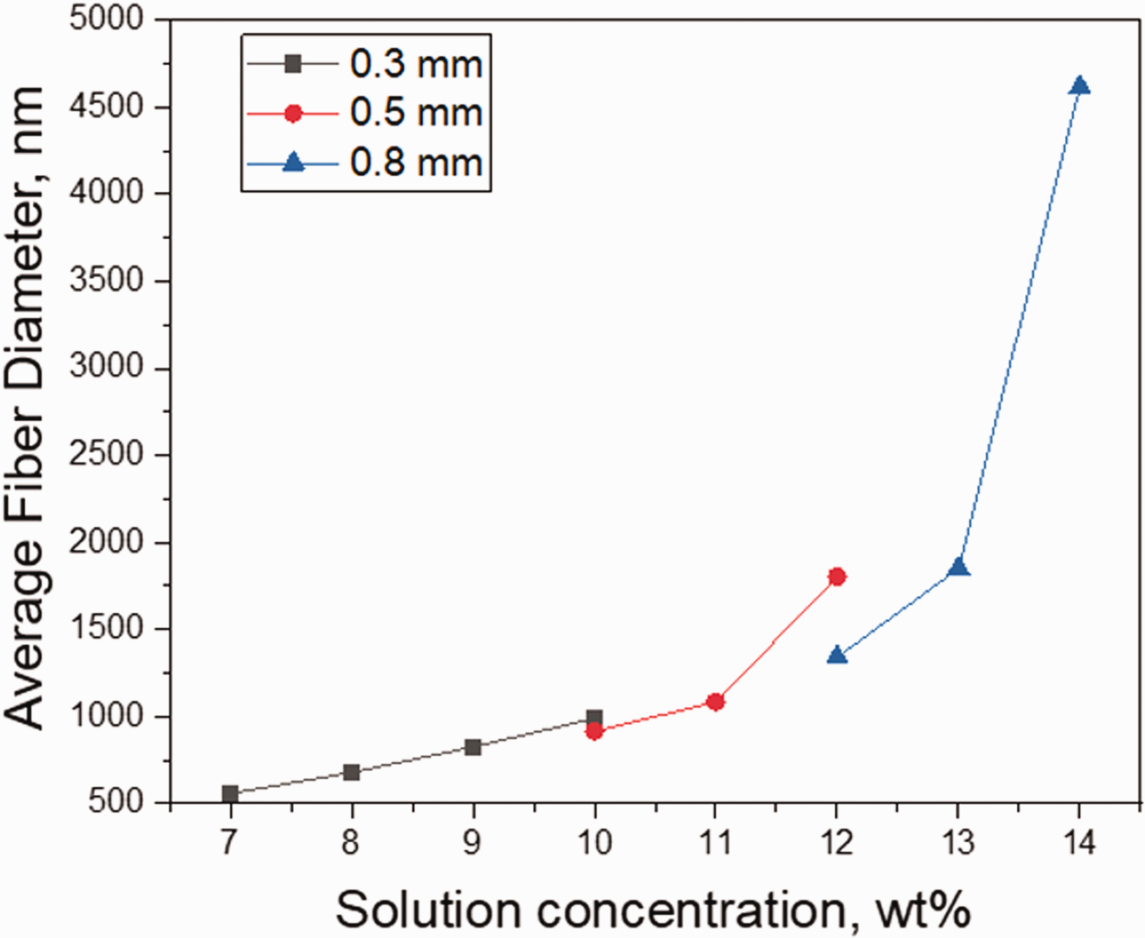
Average fiber diameter versus polymer concentration.
Nozzle diameter
In centrifugal spinning, the amount of ejected polymer solution is directly related to nozzle diameter. Larger amount of polymer is delivered with larger nozzle diameter. Three different nozzle diameters, 0.3 mm, 0.5 mm and 0.8 mm were used to investigate the effect of nozzle diameter on the average fiber diameter and SEM images were shown in Figure 5. The average fiber diameter increased significantly with increasing nozzle diameter when the other parameters kept constant, polymer concentration of 11 wt. %, feeding rate of 60 ml/h, collector distance of 20 cm and rotational speed of 4000 rpm. The average fiber diameter was 997 nm, 1084 nm, and 2178 nm, respectively, for the nozzle sizes of 0.3 mm, 0.5 mm and 0.8 mm. Increasing average fiber diameter with increasing nozzle diameter were also reported by Fang et al. [3] for centrifugally spun fibers. Leng et al. [18] also fabricated finer polystyrene fibers by using smaller nozzle size due to lower amount of solution extraction per unit time [18].

SEM images of centrifugally spun PAN nanofibers produced by using different nozzle diameter (0.3 mm, 0.5 mm, 0.8 mm). Polymer concentration 11%, rotational speed: 4000 rpm.
Rotational speed
Rotational speed is another important parameter that affect the morphology and average fiber diameter. The effect of rotational speed was investigated by altering the rotational speed from 3000 rpm to 7000 rpm while keeping other parameter constant. Figure 6 shows SEM images of PAN nanofiber produced by using 0.3 mm nozzle diameter and different rotational speeds. As seen from Figure 6, the fiber with the lowest average fiber diameter of 680 nm produced with the rotational speed of 4000 rpm. The average fiber diameter was 1650 nm at 3000 rpm and average fiber diameter of 1759 nm, 1660 nm and 1646 nm were observed for the rotational speeds of 5000, 6000 and 7000 rpm. High rotational speeds promote the polymer chain elongation and thus thinner fibers were observed by increasing the rotational speed up to 4000 rpm. When rotational speed is increased, the surface tension and viscosity of the solution remains the same, thus the centrifugal force exerted on the solution per volume increased thus smaller fiber diameter was observed. However, at higher speeds, over 4000 rpm, average fiber diameter increased. This result could be attributed to rapid solvent evaporation at high speeds. At the speeds above 4000 rpm, solvent evaporates rapidly and polymer jets solidifies before elongation that leads to large fiber diameter. At lower rotational speeds, below 4000 rpm; at 3000 rpm; there is not enough speed for the polymer jet to elongate and thin, therefore higher average fiber diameter was observed. Similar results was also observed by Stojonovska et al. [19] for lignin fibers. Increasing the rotational speed from 6000 to 8500 rpm led to smaller fiber diameters, from 532 to 476 nm, however when rotational speed was further increased to 11,000 rpm, the average fiber diameter was found to be 521 nm [19]. Similarly, for the nozzle size of 0.5 mm and 0.8 mm, the lowest average fiber diameter was seen when the rotational speed was 4000 rpm. As seen from Figure S3, the average fiber diameter was 4224, 1804, 3401, 3456 and 4209 nm at the speeds of 3000, 4000, 5000, 6000 and 7000 rpm, respectively while using the nozzle size of 0.5 mm. Figure S4 shows the SEM images for the PAN fibers produced at varying speeds and by using 0.8 mm nozzle. The average fiber diameter was 2354, 1852, 2883, 3283, 3391 nm, respectively, for the speeds of 3000, 4000, 5000, 6000 and 7000 rpm. It can be concluded that 4000 rpm was the optimum speed for the smallest fiber diameter among all rotational speeds and for all nozzle types.

SEM images of centrifugally spun PAN nanofibers produced by using different rotational speeds (3000-7000 rpm). Nozzle diameter: 0.3 mm, polymer concentration 8%.
Nozzle length
Figure 7 shows SEM images for PAN fibers fabricated by using different nozzle lengths of 1.3 cm, 2.5 cm and 3.8 cm from 13 wt. % solution at 4000 rpm, with the feeding rate of 60 ml/h. As seen from the figure, increasing nozzle length led to decreased average fiber diameter. The average fiber diameter were 7705 nm, 2824 nm and 1765 nm for the nozzle lengths of 1.3 cm, 2.5 cm and 3.8 cm, respectively. The result could be attributed to pressure drop occurred at the nozzle. The rate of the outflow of the solution decreased with increasing nozzle length until it left the nozzle [87]. Thus, it had more time to form the polymer jet and thinning the jet before reaching to the collectors which resulted in lower average fiber diameter. Decreased diameter with increasing nozzle length was also reported for PLA fibers [87].
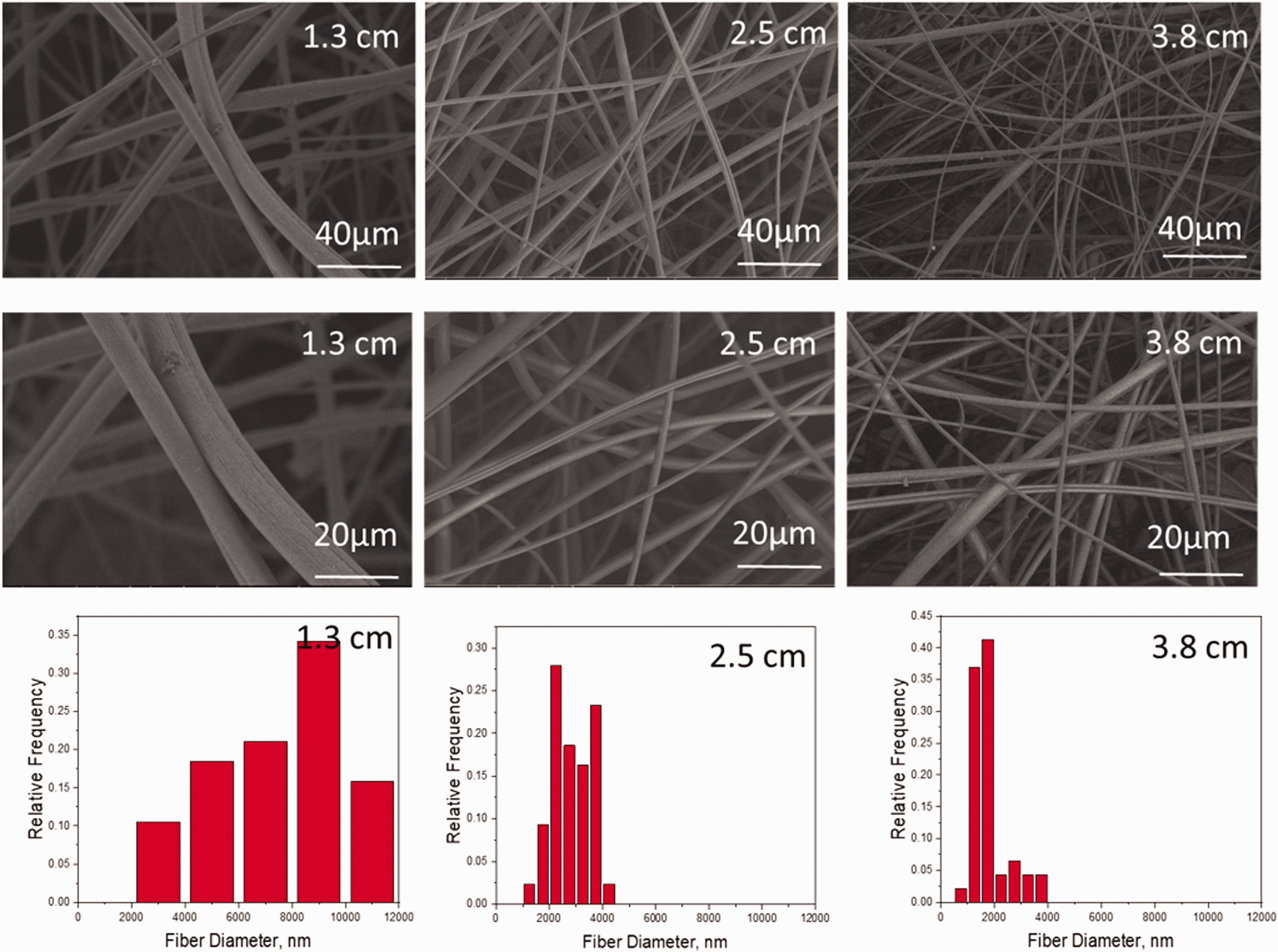
SEM images of centrifugally spun PAN nanofibers produced by using different nozzle lengths (1.3, 2.5, 3.8 cm). Nozzle diameter: 0.8 mm, polymer concentration 13%.
Feeding rate
Feeding rate was controlled with a syringe pump and the effect of feeding rate on fiber morphology was studied. For the nozzle diameter of 0.3 mm, PAN fibers were produced with varying feeding rates, from 8 ml/h to 240 ml/h. Figure 8 shows SEM images of PAN fibers produced from 8 wt. % solution at 4000 rpm and the feeding rated varied between 8 to 240 ml/h. As seen from the figure bead free fibers with the lowest average fiber diameter of 680 nm was fabricated at the feeding rate of 60 ml/h. At the lower feeding rates, bead formation was seen due to lack of solution and at high feeding rates, average fiber diameter increased slightly.
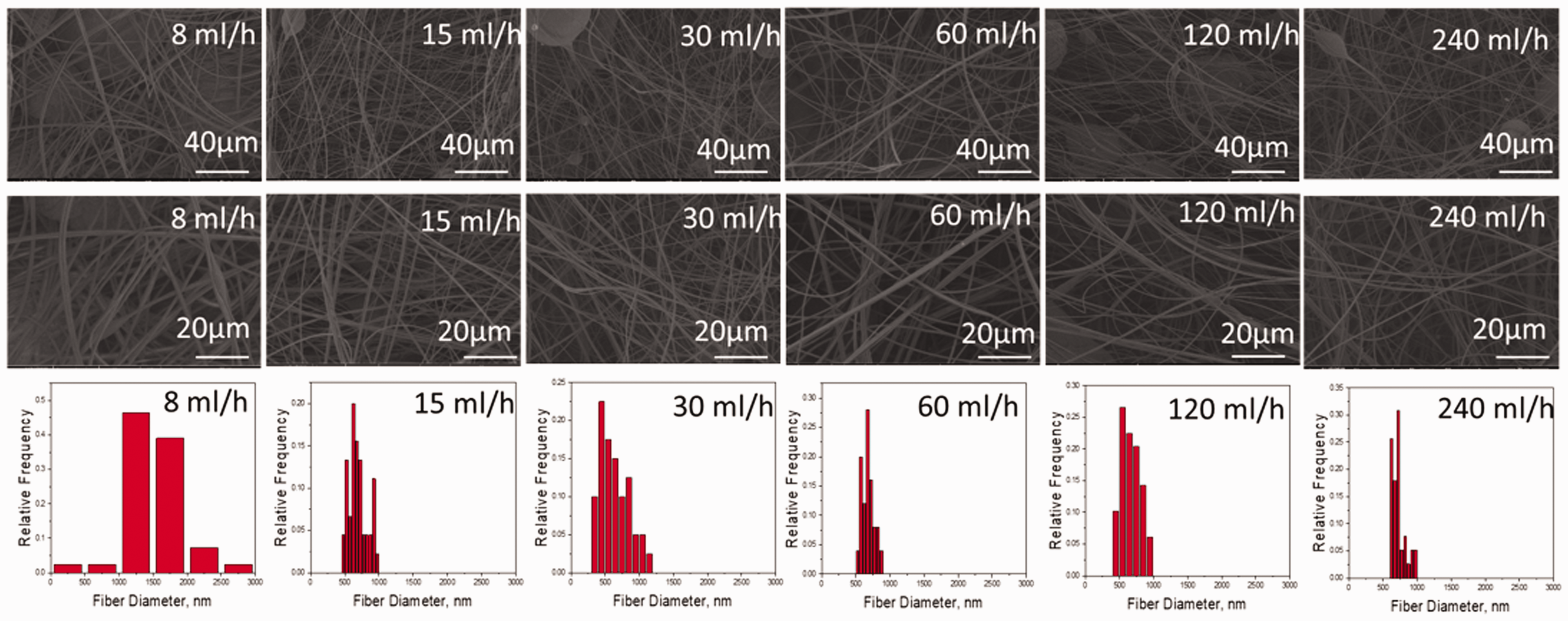
SEM images of centrifugally spun PAN nanofibers produced by using different feeding rates (8-240 ml/h). Nozzle diameter: 0.3 mm, polymer concentration 8%.
Figure S5 shows SEM images of PAN fibers produced with the 0.5 mm nozzle size, rotational speed of 4000 rpm for 12% PAN concentration. Bead free fibers were observed for the feeding rates of 81,530, 60, 120 ml/h and the average fiber diameter were 2215 nm, 1403 nm, 1435 nm, 1356 nm and 1818 nm for the feeding rates of 81,530, 60, 120 ml/h, respectively. Similarly, as seen from Figure S6, the average fiber diameter decreased with increasing feeding rates for 13% PAN concentration. The average fiber diameter were 5721 nm, 3136 nm, 2239 nm and 1852 nm for the feeding rates of 8, 15, 30 and 60 ml/h, respectively. The fiber formation was influenced by solution concentration and nozzle size. At low concentration larger range for feeding rate was studied and fiber formation was observed whereas with increasing concentration only limited feeding rate, 8-60 ml/h, led to fiber formation. No fiber formation was seen below or above this range for 13% PAN concentration. Hammadi et al. [15] also reported varying spinnability for changing viscosity and nozzle size. For highly viscous solutions, large nozzle sizes led to fiber formation, while smaller nozzle sizes was used with low viscosity solutions.
Collector distance
In centrifugal spinning, distance between the nozzle and the collector controls solvent evaporation, jet elongation, and solidification. The effect of collector distance on fiber morphology was studied by using three nozzle diameters. Figure 9 presents SEM images of PAN fibers fabricated from 8 wt. % solution at 4000 rpm with the varying collector distances, 20 cm, 25 cm and 30 cm. As seen from the figure, no significant change was observed in average fiber diameter and fiber morphology. Figure S7 show SEM images of PAN fibers produced with 0.5 mm nozzle size with 12% PAN concentration. Similarly, no significant change in average fiber diameter were observed by changing the collector distance. The average fiber diameter were 1804 nm, 1767 nm, and 1758 nm, respectively. Figure S8 show SEM images for PAN fibers for different collector distances for 13% PAN concentration and the average fiber diameter was 1876 nm, 1852 nm and 1894 nm, respectively. Changing the collector distance did not result significant change at studied concentrations. This indicates that 20 cm is an enough for the evaporation of the solvent to fabricate nanofibers. In accordance with these results, previous studies also reported that as collector distance altered, average fiber diameter did not change significantly [97]. Zander [92] studied different the collector distances of 10, 12 and 14 cm and produced PCL nanofibers and stated no statistical difference in fiber diameters. Li et al. [83] also reported no significant difference on fiber diameter with changing collector distance for centrifugally spun PS nanofibers.

SEM images of centrifugally spun PAN nanofibers produced by using different collector distances (20, 25, 30 cm). Nozzle diameter: 0.3 mm, polymer concentration 8%.
Statistical analysis and optimizing average fiber diameter
ANOVA results for average fiber diameter was displayed in Table 3. It is seen that concentration; nozzle diameter and nozzle length are highly significant (p < 0.01) on average fiber diameter. In contrast, the collector distance, rotational speed, feeding rate showed non-significant effect on the average fiber diameter with a p value of above 0.05.
ANOVA table for average fiber diameter.

*(p < 0.05) significant, (p < 0.01) highly significant.
Figure 10 shows the effect of different process and solution parameters on average fiber diameter. It is seen from the figure that average fiber diameter varies significantly, ranging from 558 nm to 1759 nm, depending on process and solution parameters. Figure S9 displays the effect of nozzle diameter and nozzle length. Figure S10 shows the main effect plot for fiber diameter as a function of spinning solution concentration, nozzle diameter and nozzle length. The diameter mean values increases with increasing concentration, nozzle diameter and nozzle length. In addition to the main effects, interaction effect between concentration × nozzle diameter and concentration × rotational speed has been shown in Figure S11. These graphs show that the increasing the concentration and nozzle diameter will result in increased average fiber diameter. SEM and TEM images of the CS and ES nanofibers are also shown in Figure S12. The average fiber diameter of electrospun 8 wt. % PAN was 592 ± 92 nm whereas that of centrifugal spun 8 wt. % PAN was 680 ± 87 nm. Similar morphology and average fiber diameter range for centrifugally spun and electrospun fibers were also observed by Yong et al. [90]. When 7.5 wt. % PVA nanofiber was electrospun, the average fiber diameter was observed to be as 537 ± 49 nm and that of centrifugal spun fiber was observed to be 510 ± 48 nm.
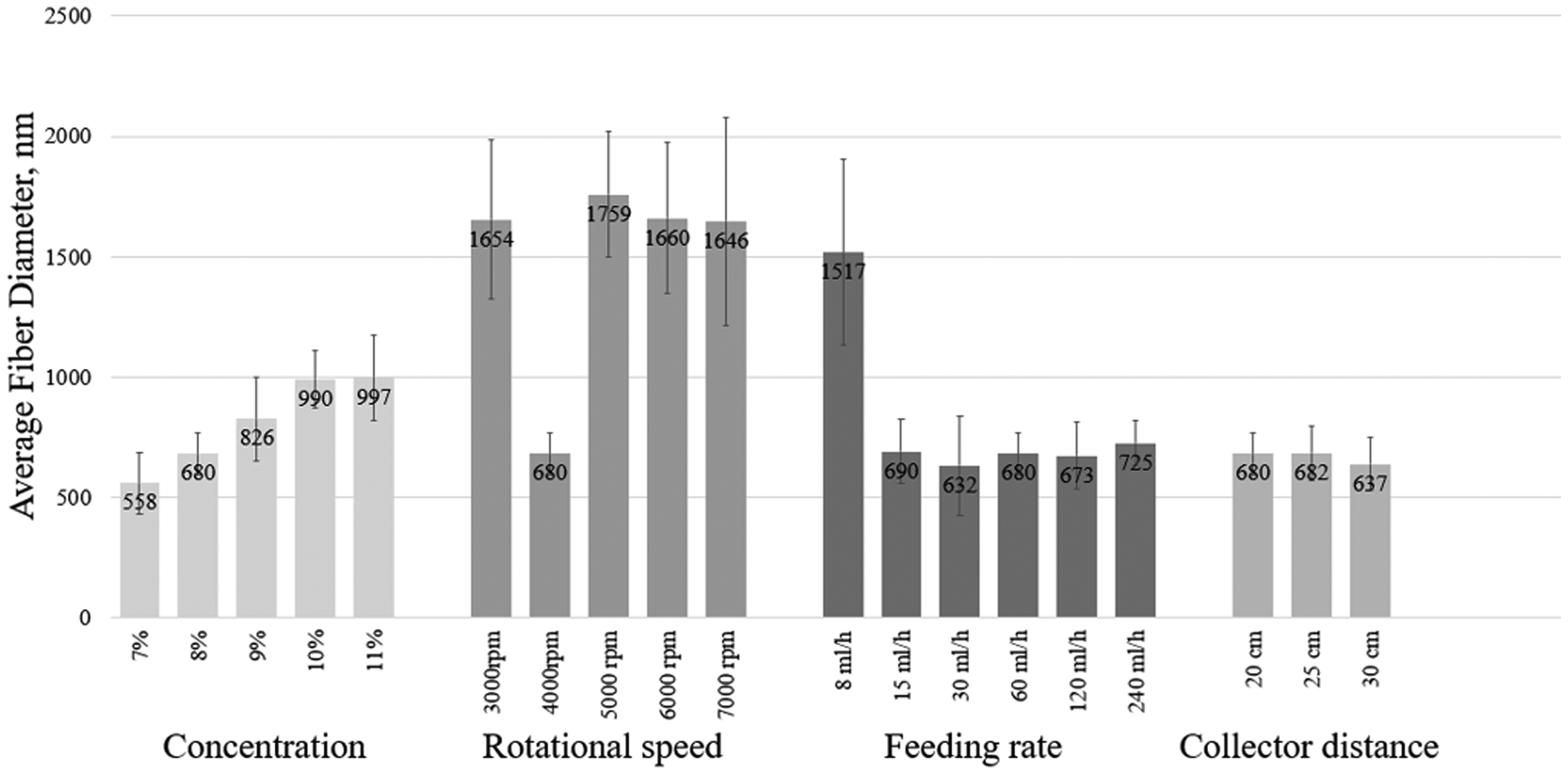
The effect of different solution and process parameters on average fiber diameter.
Ionic conductivities of PAN nanofibers
Ionic conductivities are critical for nanofiber separators and they directly affect the performance of the separators in batteries [96]. Ionic conductivities of liquid electrolyte-soaked membranes were measured by electrochemical impedance spectroscopy and the results were reported in Table 4. The conductivities were 3.0 mS/cm, 2.9 mS/cm, 2.6 mS/cm and 2.4 mS/cm, respectively, for the nanofibers fabricated by using 7%, 8%, 9% and 10% PAN solutions. The higher concentration values led to increased average fiber diameter and thus decreased ionic conductivities. Ionic conductivities were affected by morphology and average fiber diameter and increased ionic conductivities with decreased average fiber diameter were reported for PVDF and PAN nanofiber separators as well [31,102].
Ionic conductivities.

Conclusion
PAN nanofibers were fabricated via fast and safe nanofiber production technique and the effect of solution and process parameters on fiber morphology and fiber diameter were studied systematically. The effect of concentration, rotational speed, feeding rate and collector distance were studied by using three different nozzle diameters. For all studied nozzle diameters, increasing concentration resulted in larger average fiber diameter. The fibers with the lowest average fiber diameter was observed when the rotational speed was 4000 rpm. The optimum feeding rate was 60 ml/h considering the average fiber diameter and bead formation. The effect of collector distance on average fiber diameter was found insignificant. 8 wt. % PAN solution was centrifugally spun with the rotational speed of 4000 rpm, feeding rate of 60 ml/h, collector distance of 20 cm and nozzle diameter of 0.3 mm and bead free nanofibers with the average fiber diameter of 680 ± 87 nm was observed.
Footnotes
Declaration of conflicting interests
The author(s) declared no potential conflicts of interest with respect to the research, authorship, and/or publication of this article.
Funding
The author(s) disclosed receipt of the following financial support for the research, authorship, and/or publication of this article: This research was supported by The Scientific and Technology Research Council of Turkey (TUBITAK). Project Number: 219M348.
Supplemental material
Supplementary material for this article is available online.
References
Supplementary Material
Please find the following supplemental material available below.
For Open Access articles published under a Creative Commons License, all supplemental material carries the same license as the article it is associated with.
For non-Open Access articles published, all supplemental material carries a non-exclusive license, and permission requests for re-use of supplemental material or any part of supplemental material shall be sent directly to the copyright owner as specified in the copyright notice associated with the article.