
Abstract
This paper presents a transversely hyperelastic constitutive model for predicting mechanical properties of flexible composites under unidirectional tension. A strain energy function which reflects the behavior of anisotropic elastic material is decomposed into three parts: matrix, fiber and fiber-matrix interaction. The fiber-matrix interaction was decomposed into in-plane shear stresses and out-of-plane shear stress, the in-plane shear stresses were related to the fiber elongation invariants, and the out-of-plane shear stress was related to the fiber elongation invariants and the matrix invariants. The fiber-matrix interaction considering shear factor was established. Based on fiber reinforced continuum mechanics, a transverse hyperelastic constitutive model including fiber, matrix and their interaction is developed. The transversely hyperelastic constitutive model is verified by the uniaxial tension tests. The constitutive model can be used to design the flexible structure of stratospheric airship.
Introduction
The stratospheric airship (SSA) has received much attention with potential applications in radio relay telecommunications service, earth observation science and other fields [1]. Envelope material (flexible flim composite) is the main structure of the stratospheric airship, which determines the long endurance flight performance [2]. The complex stratospheric environment requires a kind of lightweight flexible flim composites with high performance and weather resistance. Laminated fabrics (flexible film composites) were widely used in stratospheric airships due to its excellent mechanical performance and weather resistance [3].
Over the past several decades, many experiments of the flexible film composites had been widely carried out. The experiments were decomposed into two types: tear tests with initial crack and tensile tests without initial crack. Several tear methods were used to study the tear behavior. Tear methods include trapezoidal tear method [4–6], central slit tear method [7–12], single edge notch tear method [2], wing-shaped tear method [13] and tongue tear method [14]. Flexible composite materials have also made progress in elastic mechanics constants and failure criteria under uniaxial and biaxial tensile tests without initial crack. The failure criterion [15,16] and the determination of elastic constants [17] of the material are studied under uniaxial tensile tests with different off-axial angles. In order to accurately characterize the mechanical properties of flexible composite materials in service environment, the failure criterion of stress ratio [18] and the measurement of elastic constant of flexible composite [19] were obtained under biaxial tensile tests.
Various constitutive models have been developed to explain the mechanical behavior of envelope materials. Linear elastic orthotropic models [17,20] were widely used in flexible composites for their simplicity. Linear constitutive models were commonly used to measure elastic constants of flexible composites. In order to accurately capture the nonlinear mechanical behavior of flexible composite, nonlinear constitutive models were also studied extensively. Non-orthogonal constitutive models [21–23] were developed for characterizing woven composites in phenomenological model. Hyperelastic constitutive models based on strain invariants were also studied extensively. The strain energy function was decomposed into four parts (fiber, matrix, fiber-matrix shear interaction and fiber-fiber interaction). The fiber-fiber interaction of flexible composite was usually not considered in uniaxial tensile tests [24]. The fiber-matrix interaction was usually not considered in biaxial tensile experiments in warp and weft directions [25]. Yao et al. [26] developed a constitutive model for plain weave fabrics considering all parts. However, it must be pointed out that the above constitutive models were in-plane models.
The mechanical behavior for the flexible composites were reviewed. Considering that the flexible composite is very thin (in this paper, the thickness is 0.21 mm), the existing constitutive models are all two-dimensional plane models. The out of plane stress also had a great influence on the mechanics of flexible composites. In this paper, a transversely isotropic hyperelastic constitutive model is developed for flexible composites. The structure of this paper is given as follows: in the next section, based on fiber reinforced continuum mechanics theory, a transversely isotropic hyperelastic constitutive model for large deformation of flexible composites is developed. The new model can not only describe the in-plane shear stress, but also the out of plane shear stress. The new model can provide theoretical support for the design of flexible composite materials. Then, uniaxial tension tests were introduced in detail. In ‘Numerical results and model validation discussion’ section, the parameters of constitutive model obtained from experimental data and verified with tests. In the penultimate section, the results of constitutive model were discussed. A brief summary of the work was presented in the final section.
Transversely hyperelastic constitutive model
Flexible film composites can be treated as laminated composite structures with fibers embedded into matrix. In the model, the fibers and matrix are assumed to be perfectly bonded together without considering separation between the fiber and matrix. Based on Spencer’s fiber reinforced continuum mechanics theory [27], a transversely hyperelastic constitutive model for large deformation responses of flexible composite is developed.
General format for the constitutive model
A strain energy function for an anisotropic hyperelastic material for large deformation response is defined to represent phenomenological model of envelope material. The strain energy function can be expressed as a scalar function of the initial fiber direction a0d (a01: warp direction, a02: weft direction) and the right Cauchy-Green deformation C=FTF. Here F=∂x/∂X is the deformation gradient tensor. The elastic response of the envelope material is assumed to originate from the resistance of the matrix and fiber. There, the strain energy function is given by

Where WM is the strain energy contribution from the ground matrix, WF is the contribution from the fiber elongation.
The strain energy function can be written in term of principal invariants Ii as

Where the invariants are given by

Where I4d, I5d are invariants, and subscript d = 1, 2 represents the stretches of warp and weft, respectively. I5d is another strain invariant, which is also related to fiber elongation. In this paper, the envelope material is assumed to be an incompressible material.
Material models for matrix and fiber
The matrix model is assumed to be incompressible material. The strain energy function WM can be described by a simple neo-Hookean hyperelastic model with incompressibility

Here C10 is the only one material parameter of matrix and C10 is related to shear modulus of the matrix. vm represents the volume fracture of matrix.

The strain energy function WF originates from fiber elongation. A simple nonlinear fiber strain energy function [28,29] can be expressed as
Here k1d and k2d are material parameters of fiber strain energy function. Vfd represents the volume fraction of fiber, and d = 1, 2 represents the volume fractures of warp and weft. In this paper, vf1 is assumes to equal to vf2.
Multiplicative decomposition of deformation gradient
Guo et al. [30] use a specific multiplicative decomposition of the deformation gradient to constructing the strain energy function for transversely isotropic hyperelastic materials. In the model, any isochoric deformation can be divided into two parts: the first part is uniaxial deformation along the fiber, the second part is all remaining shear deformation. This method has been presented in detail in literature [30] and only a brief description is given here.
Let the origin fiber direction
Therefore, in the

By choosing a suitable
The fiber deformation in uniaxial tensile is given by

Here, F*12 represents in-plane shear, F*23, F*23 represent out-of-plane shears. These shear deformations can be related to the invariants of

Strain energy function
Denoting the volume fraction of the fibers and matrix as vf and vm, respectively (vf+vm=1, vf=vf1+vf2,vf1=vf2). When uniaxial deformation along the fiber direction,

The shear strain energy of fiber-matrix is related to the elongation of fiber and matrix. The shear strain energy of fiber-matrix is given by

Where I1(F*fd) = λ2Fd+2/λFd=I4d+2I−1/24d, is the first invariant of tensor
The shear deformation of fiber matrix is the result of the interaction of fiber and matrix. Therefore, the shear strain energy is related to the invariants of fiber and matrix. The fiber-matrix shear strain energy is given by

The strain energy of flexible composite consists of three parts: fiber, matrix and fiber-matrix interaction. The strain energy of the fibers, matrix and fiber matrix interaction has been given. Now the strain energy function of flexible composite called Uretek-3216LV is given by

As can be seen from equation (13), a total of six material parameters and the physical meaning of each term are very clear. These material parameters can be obtained from experimental data through the following procedure: Match experimental results of uniaxial tensile test in warp direction to obtain the material parameters k11 and k21. Similarly, the material parameters k12 and k22 can be obtained from experimental results of planar tests in weft direction. Match experimental results of uniaxial shear tensile tests with least-square method to obtain the material parameter C10 and m
The procedure provides the guidelines for experimental results for the material characterization of envelope material. The second Piola-Kirchhoff stress obtained directly from the hyperelastic strain energy function equation is given by S=∂W/∂C-pC−1. p is the pressure. The Cauchy stress

Specific application to the envelope materials
In this part, the constitutive model is applied to flexible composite in detail. For a uniaxial tensile deformation in which the principal axes are shown in Figure 1. The deformation gradient F is given in equation (15).


Uniaxial tensile deformation of envelope materials.
Where λi is the principal stretch along the i-th principal direction. The relationship of λ1 and λ2 can be expressed as

Where θ01 is the original angle between warp direction and loading direction, θ01=θ02=45°, θ is the angle between the warp fiber and the loading direction at any time during the loading process. The stretch in the structural direction denotes tensor
In this paper, when the envelope material is stretch under off-axial angles of uniaxial tension, the fiber length is assumed to be unity (λf=1). The left Cauchy-Green deformation tensors C and right Cauchy-Green deformation tensors B are expressed as
The relationship between invariants I1, I2, I3 and principal stretches λi can be expressed as

In this paper, the general form of unit vector for each fiber direction in 1-2 plane are considered as

θ01 is the initial angle between the warp direction and loading direction. The invariants I41 and I42 shown in Figure 1 are expressed as

Substituting equations (15) to (21) into equation (14), the Cauchy stress in constitutive model can be expressed as


A total of six parameters can be obtained from uniaxial tensile tests. In tensile tests, the traction boundary conditions need to be satisfied. In other words, when the loading direction is along the x1 direction (σ1≠0), the other directions are imposed the constraints to zero (σ2=σ3=0). The σ1, λ2, λ3 can be obtained from equations (22) to (24) when a principal stretch λ1 is given. Engineering stress and engineering strain are given in tensile experiments. To compare with the experimental data, the Cauchy stresses in the constitutive model are transferred in engineering stresses in the following numerical simulations.
Experimental testing
Materials
The stratosphere airship envelope material is a multi-layer flexible composite material Uretek-3216LV with thickness of 0.21 mm. An areal density of envelope material Uretek-3216LV is 200 g/m2. As shown in Figure 2, the envelope material is composed of five function layers including wearable layer, ultraviolet layer, the structural layer, the gas retention layer and sealing layer. Tedlar PVF film is selected as the helium barrier and the UV radiation protection. Vectran yarns are selected as structure layer. The warp and weft density of the fabrics are both 17 × 12 threads/cm, and the warp and weft yarns are both 200 Denier. Ethylene vinyl alcohol copolymer is selected as sealing layer. To simplify the constitutive model, the laminated films are regard as matrix. The envelope material is composed of fibers and matrix in simplified model.

Envelope material. (a) Macro envelope material (b) envelope layout (c) Simplified model.
Uniaxial tensile tests
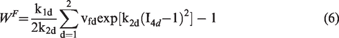
The specimen of flexible composite with three directions (0°, 45°, 90°) are conducted. Strip specimens are widely used in uniaxial tensile behavior of envelope materials [31]. The geometry dimension of the uniaxial specimen was determined to be 300 mm in length and 50 mm in width, the effect length of tensile region was set to be 200 mm. The specimens are prepared with off-axial angles of θ (θ=0°, 45°, 90°) from the vertical direction along loading direction. Five specimens were prepared for each off-axial direction of uniaxial tension tests. All the specimens are loaded in WDW-100 machine by displacement mode with the speed of 20 mm/min. The ultimate tensile load of the tensile testing machine is 1 ton, the load control precision is 0.01 N, and the displacement control precision is 0.001 mm. All the tests performed at room temperature of 25 °C and a relative humidity of 60%. The specimen and the uniaxial tensile test machine are shown in Figure 3.
a) The specimen of uniaxial tensile tests (units: mm) b) the uniaxial tensile test machine.
Uniaxial tension results
Considering the mechanical behavior of the specimen have obvious difference between the on-axial tension (0° and 90°) and off-axial tension (45°), the mechanical of specimen with different off-axial angles are discussed respectively. The mechanical behavior of specimen with on-axial tension is shown in Figure 4. Mechanical behaviors of specimens in warp and weft directions are similar and both show obviously nonlinear behavior. The stress-strain curve of uniaxial tension tests in 45° direction is shown in Figure 5. The stress-strain curve of the specimen in 45° direction is S-shaped.

Stress -strain curves of the uniaxial tensile tests in 0°and 90°directions.

Stress -strain curve of the uniaxial tensile tests in 45° direction.
Numerical results and model validation discussion
Fiber parameters
The fiber parameters can be obtained from uniaxial tensile tests along the warp direction or weft direction. Based on the literature [32], the volume fraction of matrix and fiber is 36% and 64% respectively. The engineering stress σ1 in warp direction is given by

The parameter k11 is 4028 MPa, k21 is −11.56 (R-square is 0.98).
The engineering stress σ1 in weft direction can be expressed as

The parameter k12 is 2640 MPa, k22 is −5.787 (R-square is 0.96). The comparison between the model and test values in warp and weft directions is shown in Figure 6. The results show that the test values are in good agreement with the model values.

The comparison between the model and test values in warp and weft directions.
Matrix and fiber-matrix parameters
The matrix and fiber-matrix parameters can be obtained by uniaxial tensile tests with off-axial angles of 45°. Combing the equations (22) to (24) can obtain the matrix and fiber-matrix parameters. Imposing the constraints σ2=0 and σ3=0 permits equation (22) to be solved for matrix and fiber-matrix parameters C10 and m. The parameters (R-square is 0.9622) are:

The comparison between the model and test values in warp and weft directions is shown in Figure 7. The model predicted values have a good agreement with the test values.

The comparison between the model and test values in 45° direction.
Model validation
In this section, the constitutive model is validated. The stress-strain curves of constitutive model is to compare the corresponding experimental data are shown in Figures 6 and 7. The results show that the predicted value of the model is in good agreement with the experimental data. The constitutive model can be used to design the flexible structure of airship. Moreover, the geometric shape changes are also considered.
When the flexible composite is stretched along the fiber direction, the angle between the two sets of fibers keep constant. Stretch in the x2 direction versus stretch in the x1 direction for flexible composite in warp and weft directions is shown in Figure 8.
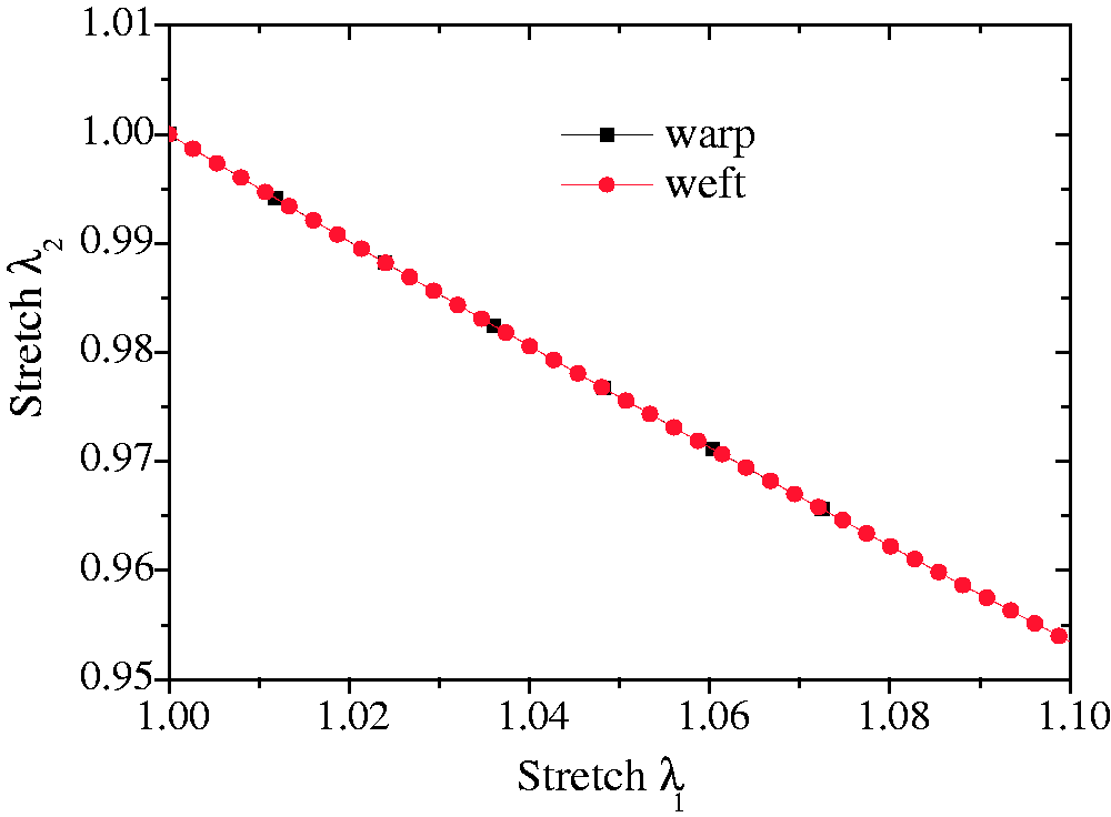
Stretch in the x2 direction versus stretch in the x1 direction for flexible composite in warp and weft directions.
When the angle of warp direction and loading direction is 45°. Angle changes between the fibers for flexible composite is shown in Figure 9. Stretch in the x2 direction versus stretch in the x1 direction for flexible composite in 45° direction is shown in Figure 10.

Angle changes between the fibers for flexible composite in 45° direction.

Stretch in the x2 direction versus stretch in the x1 direction for flexible composite in 45° direction.
Further investigations of the constitutive model
The strain energy function of flexible film composite can be divided into three parts: fiber, matrix and fiber-matrix shear interaction. The contributions of three parts (matrix, fiber and fiber-matrix interaction) of the flexible composite under uniaxial tests with different off-axial angles are different. The contributions of each part of the mechanical behavior of the flexible composite are discussed under on-axial and off-axial tension.
When the fibers parallel to the loading direction, only the fibers contribution to the extension similar to phenomenological model [24]. In other words, the matrix and fiber-matrix contribution little to the extension.
When the angle of loading direction and warp fiber is 45° direction, the matrix and fiber-matrix shear interaction are contribution to the extension. Two patrts stress versus stretch in the x1 direction for flexible composite in 45° direction is shown in Figure 11. “Total” denotes the total shear stress. “Matrix” and “Fiber-matrix” denotes the matrxi stress and fiber-matrix shear interaction stress. The contribution of two component stresses to the constitutive model is different at different stretch stages. When the stretch is less than 1.31, “matrix” shear stress is of great important for constitutive model. However, when the stretch is more than 1.31, “fiber-matrix” shear stress is of great important for constitutive model.

Two patrts stress versus stretch in the x1 direction for flexible composite in 45° direction.
Fiber-matrix shear stress can be decomposed into two parts: along fiber shear stress and transverse shear stress. Two shear components stress versus stretch in the x1 direction for flexible composite in 45° direction is shown in Figure 12. “Total” denotes the total shear stress. “Along fiber” and “Transverse” denote along fiber shear stress and transverse shear stress respectively. the contribution of two components shear stress for the fiber-matrix shear stress is defferent. When the stretch is less than 1.31, “Along fiber” shear stress is of great important for the fiber-matrix shear stress. However, when the stretch is more than 1.31, “Transverse” shear stress is of great important for the fiber-matrix shear stress.

Two shear components stress for fiber-matrix shear stress versus stretch in the x1 direction in 45° direction.
Conclusion
In this paper, a composites-based hyperelastic constitutive model is developed to characterize the nonlinear anisotropic response of flexible composites. In the model, the matrix model is modeled as an incompressible neo-Hookean material, while the fiber model is exponential form material. The fiber-matrix interaction was decomposed into in-plane shear stresses and out-of-plane shear stress, the in-plane shear stresses were related to the fiber elongation invariants, and the out-of-plane shear stress was related to the fiber elongation invariants and the matrix invariants. The fiber-matrix interaction considering shear factor was established. Based on fiber reinforced continuum mechanics, a transverse hyperelastic constitutive model including fiber, matrix and fiber-matrix interaction is developed. The predicted results of constitutive model have a good agreement with the results of uniaxial tensile tests. The results show that the out-of-plane shear stress is an important term to constitutive model. When the uniaxial loading direction and the warp fiber formed an angle of 45 degrees, the specimen stretch exceeded 1.31, the out-of-plane shear stress played a major role.
Footnotes
Declaration of conflicting interests
The author(s) declared no potential conflicts of interest with respect to the research, authorship, and/or publication of this article.
Funding
The author(s) received no financial support for the research, authorship, and/or publication of this article.