
Abstract
We present the critical and systematic investigations on the normal/regular types of carbon black to trigger the conductivity of polymer nanocomposite in developing commercially viable coated flexible fabric. Regular grade carbon blacks are utilized to develop conductive fabric via nanocomposite preparation and application by knife-over-roll coating (average 90 microns thick). The study suggests, tailored secondary microstructure of carbon black particles having a diameter of 30 nanometers (with ∼0.6 packing fraction, 5.815E + 19 per cc charge carrier density, 0.774 ratios of Hall coefficient) has a profound effect on conductivity. The microstructure of carbon black is altered by the shearing force of a mechanical stirrer in a viscous solution of natural rubber latex and polyvinyl alcohol then self-restructured when an excess amount of water is evaporated by high-temperature drying. Thus, the tailored secondary microstructure of carbon black with a diameter of 30 nanometers provides the highest charge carrier density as compared to other types of carbon black used. We found that the attained conductivity (>113 S/m) in this process is 98% of the predicted value as per the classical model. This technique can be exploited to use normal grade carbon black in replacement of conductive grade carbon black and other carbonaceous material like graphene and carbon nanotube. We envision that this easily scalable, commercially viable technique can be utilized for large scale production of conductive fabric.
Keywords
Introduction
Developments of conductive textiles using carbonaceous conductive fillers have been initiated long before for various applications like sensors [1], electromagnetic interference shielding [2], etc. Conductive grade carbon black(CB) [3–6] carbon nanotubes [7–9] graphene [10,11] and carbon fiber [12] have been tried to develop conductive textiles. In a review, Wang J. summarized the uses of carbon nanotubes to develop electrochemical biosensors [13]. Over the last two decades, enormous attention has been paid on the carbon nanotube and graphene as conductive fillers along with conductive polymers [14–19] and metal nanoparticles [20–23]. Combination of conductive grade CB and carbon nanotubes [24,25], CB and graphene [26], CB and carbon nanofibers [12], carbon black and polyaniline [27], polyvinylpyrrolidone and carbon nanotube [28], polypyrrole and silver [29], polypyrrole and multi-walled carbon nanotube, as well as silver [30], multifunctional graphene and polyvinyl phosphonic acid [31], have also tried for developing conductive polymer nanocomposites for various applications. However, the use of normal grade CB particles as the conductive filler have been overlooked regardless of its availability, low cost, and durability. Although, the effectiveness of carbon nanotube [30] and graphene [31] as conductive fillers have been established [7,32–34], limited availability and high cost restrict their implementation for large scale production. Similarly, the use of conductive polymers [35] for developing conductive textiles is still a concern because of its high cost and low weather resistance. Thus, the research continues for finding a low-cost, durable, lightweight, flexible conductive textile to meet up the ever-growing demands for electro-textiles applications.
Carbon black is normally used as a reinforcing filler for the rubber compound. There are various types of CBs available on a commercial scale such as furnace black, channel black, acetylene black, and lamp black. It is customary to name CBs depending on their manufacturing processes (e.g. furnace black implies that furnace was used to manufacture it). It is a well-known fact that surface fractal dimension [36,37] of all the amorphous CBs is almost constant (i.e. 2.2). Though their particle size, surface area, surface chemistry, secondary microstructure [38], alkalinity is varied based on the manufacturing processes (for example, furnace black is alkaline, and channel black is acidic). On the other hand, the agglomeration tendency of CBs is differed based on the particle size, surface energy, and surface functional groups [39]. Thus, the processability of CB is very much dependent on the secondary microstructure (higher surface energy result in higher structure, in turn, increases difficulties in dispersion in rubber matrix). As a result, the reinforcing capability, bulk properties, dispersibility, and electrical properties are observed to be dissimilar. It is a well-known fact that higher secondary microstructure is suitable for imparting higher electrical conductivity to the composite in contrast to the attained higher processing difficulties. The higher loading of CB in a composite is observed to be resulted in achieving a higher level of conductivity. In latex stage mixing, the loading of CB cannot be increased beyond a certain level (latex coagulates depending on acidity/alkalinity of CB) thus conductivity in the process is very difficult to achieve.
In our recent work [40], we have initiated the approach to use normal grade carbon black for developing conductive cotton fabric using the knife-over-roll coating technique and found very much promising for the purpose. We found that the attained conductivity level is comparable and somewhere better than the costly forms of carbon allotropes as well as conductive polymers when used as conductive fillers. In the present study, the various types of furnace blacks are used for optimizing the parameters of CB particles (depending on their secondary microstructural changes e.g. cluster size, shape, numbers of particles per clusters, etc.) for achieving the highest possible conductivity.
In our previous study, only one type of carbon black(furnace black) was used to develop coated conductive fabric. Herein, six different types of furnace black were tried to optimize the parameters of carbon blacks to trigger the attained conductivity using the same polymer matrix of PVA and NRL [40]. The alteration of their secondary microstructure and resultant electrical properties of the coated fabrics are investigated in detail and compared with the theoretically predicted value of conductivity. This coated fabric can be utilized for ultra-violet ray protection and electromagnetic interference shielding applications.
Materials and method
Materials
The bleached cotton fabric was procured from Raymond, India, and used for applying all types of conductive polymer nanocomposites to develop coated conductive fabrics. The base fabric was plain woven with 118 g/m2 areal density. Hot water-soluble PVA (89-90% hydrolyzed), Sigma Aldrich India, and NRL (50% solid content), Kerala Latex Pvt. Ltd. India was used for preparing an interpenetrating polymer network. The various types of furnace black, namely N134, N220, N330, N550, N650, and N774, were obtained from Himadri Chemicals, India, and used to develop conductive nanocomposites. The surface crystallinity of carbon blacks used is ≤0.48 [41]. The details of all the normal grade carbon black are given in Table 1. Polyethylene oxide emulsifier (Merck Specialties Pvt. Ltd.) was used as a stabilizing agent for the blended matrix (NRL and PVA). Carbon black when mix with NRL has a natural tendency to coagulate. Thus to avoid such difficulties polyethylene oxide and PVA was used. Moreover, under high-speed stirring, the viscous mixture is prone to entrap air into it. Turkey red oil (TRO) (70%), (Rishabh Intermediates, India) was used as the antifoaming agent which help to release the entrapped air from the mixture. Glutaraldehyde (25%) procured from Merck Specialties Pvt. Ltd. was used as the common cross-linking agent [42] for both NRL and PVA. These three chemicals are commercially available and mixable in hydrous and viscous NRL.
Basic parameters of the carbon black particles.
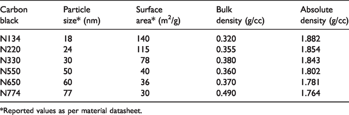
*Reported values as per material datasheet.
Preparation of nanocomposite and application technique
The optimized process parameters (Supplementary Information, Figure S1) were used to develop conductive nanocomposites as paste form using the blended polymer of natural rubber latex (NRL) and hydrolyzed polyvinyl alcohol (PVA). The optimized dose of 180 mL hydrolyzed PVA (15%, weight/volume; water solvent) is first mixed with 100 mL of NRL (50% solid content) for 5 min under high-speed mechanical stirring. Then an optimized dose of 12 mL Turkey Red Oil (TRO, 70%) is added along with 300 g of CB. The total amount of TRO and carbon is added stepwise under continuous stirring at the same speed (3000 rpm). Simultaneously, an extra amount of water is judiciously added to maintain constant viscosity (near 6000 Poise, Figure S2 in the Supplementary Information) so that the mixture can flow avoiding over dilution or coagulation (Zeta potential of the mixture varies from −12.2 mV to −15.5 mV depending on the size of carbon black). Since the addition of carbon black is observed to have resulted in the exponential increment in the viscosity. The whole stepwise addition of CB and TRO requires about 25 min. Once a uniform mixture is obtained, 3 mL of glutaraldehyde (25%) is added and mix for about 5 min. The mixture (coating paste) is then applied on one side of the plain woven, bleached cotton fabric to develop conductive coated fabric by a manual knife-over-roll coating technique (Zimmer, Austria, a photograph is added in the Supplementary Information Figure S3). The coating paste is placed on the fabric from a beaker then the fabric is drawn in between the roll and knife. As a result, a very thin layer of the paste is spread on the surface as per the set gap which is controlled by a precise thickness gauge attached to the machine. After applying the first layer of coating paste (nanocomposite), the coated fabric is dried at 95°C for 2–5 min. Such four steps are repeated to obtain a final coating thickness of about 90 microns. When we apply a viscous (to some extent heterogeneous) polymer matrix on an uneven fabric surface using a knife-over-roll coating technique, the chances of altering the continuity of a homogeneous polymer matrix is high. It is our observation that this coating thickness along with other processing parameters can provide optimal conductivity by the quoted conductive polymer nanocomposite. Finally, the coated fabric is dried and cross-linked at 140°C for 4 hours using hot air-woven. The schematic of the whole process is shown in Figure 1 and nanocomposite formulations are shown in Table 2. The loading of all CB was kept constant at 300 phr (parts per hundred gram of rubber). In our previous study, it was observed that this loading is optimum to attain the highest level of conductivity using that blended polymer matrix. The present study was concentrated to observe the effect of the types of CB due to their secondary microstructural changes only.

Schematic of the whole process.
The formulation of all the nanocomposites.

Testing and characterization
The technique of measuring the conductivity of coated fabric is shown in the left panel of Figure 2. The square-shaped coated fabric sample was placed on the gold-coated sample holder keeping the coated side upright. The cathode (A) and anode (B) were placed on the coated side of the fabric, maintaining a gap of 1 cm between them. Then required voltage was measured to pass 10 mA current through the coated polymer nanocomposite. The coating thickness was given as the input parameter to the Ecopia1 (HMS 5300) to measure the resistivity, charge carrier density, and other electrical properties of coated fabrics. The same steps (at least five) were repeated to measure the resistivity from the different places of the same sample. Then average parameters are reported. The electrical conductivity of the nanocomposites was also assessed and verified by Agilent (4338B High Resistance Meter), which is shown at the right panel of Figure 2. The circularly shaped samples (nanocomposite) were placed in between the circular sample holders. The thickness and diameter of the sample are used as input parameters to the system. One sample from each polymer nanocomposite was tested to observe the effect of frequency on the various electrical properties of the nanocomposites. The surface roughness, profile, and topography of the coated fabrics were investigated by an atomic force microscope (AFM) (Agilent technology, 5500 AFM). Tapping mode with a force constant of 48 N/m was used for the investigation. The tip material was Si3N4 with less than 10 nm tip curvature length and less than 100-micron lengths of the cantilever. To observe the surface morphology and dispersion nature of carbon particles, a field emission scanning electron microscope (FESEM) (Carl ZEISS, Merlin) was used. The combination of gold and iridium coating (10 nm thick) was applied on the surface of all the samples before taking micrographs.

Schematic of the procedure of conductivity testing.
The acceleration voltages of 5.0 kV were applied while taking the surface photomicrographs of the surface of coated fabrics or polymer nanocomposites. The absolute density of the carbon particles was measured using a gas pycnometer (Quantachrome/Ultra PYC 1200e). The density of natural rubber latex and polyvinyl alcohol in dry conditions was measured by Densimeter (Wallace Densimeter X22B). The density of nanocomposites was measured by the same technique as well as calculated from the density of the constituents of the polymer nanocomposites, considering the blend proportion.
Results and discussion
Curing characteristic and bonding mechanism of nanocomposite film on the surface of cotton fabric
The cross-linking characteristics are confirmed by FTIR spectra which are shown in Figure 3. The cross-linked NRL and PVA blended matrix is designated by NRLPVAGA. NRL contains ammonia which reacts with glutaraldehyde and forms pentane-1,5 diylidenediamene [42]. By the ene reactions, diylidenediamine is cross-linked to the NRL. The presence of the N–H group (3046 cm−1) confirms the crosslinking of NRL. On the other hand, the elimination of the O–H (3290 cm−1) group confirms the cross-linking of PVA. The shifting of acetyl keto group C = O (because 87–90% hydrolyzed PVA is used) from 1711 cm−1 to 1651 cm−1 as well as the presence of the C–O–C peak in the spectra of NRLPVAGA also supports the cross-linking of PVA by glutaraldehyde. FTIR analysis of coated fabric was also conducted but no characteristic peak was found. A very thin layer of blended polymer nanocomposite (CB loaded) is attached to the surface of cotton fabric by physical cohesion/entanglement rather than chemical bonding.

FTIR spectra of NRL, PVA and NRLPVAGA.
The addition of the different types (sizes) of CB particles in the same polymer matrix is believed to have an impact on the polymer chain mobility [43] and subsequently on the conductivity [44,45] of the nanocomposites. Similarly, the amount of crosslinking agents [46] also restricts the polymer chain mobility. In the present study, a single-optimized dose of glutaraldehyde was used (neglecting the effect of the size variation of the carbon blacks) to prepare all the nanocomposites.
Surface morphology and roughness of the coated fabrics
The surface morphology and roughness are indicative of the internal microstructure of the polymer nanocomposite. It is also useful to judge the distribution and dispersion characteristics of the filler into the polymer matrix. In the present study, a blended matrix of NRL and PVA is used for effective dispersion and improving structural parameters of carbon black for achieving a high level of conductivity. The shearing force of the mechanical stirrer breaks the aggregates of CB particles into smaller sizes in the blend polymer matrix. The fragile layer of NRL and PVA blended film acts as a barrier to re-aggregate the CB particles thus resulted in close packing. Moreover, the scrapping action (shearing forces) of the knife-over-roll helps to apply this closely packed polymer nanocomposite on the surface of the fabric. Since the structure of the filler in the polymer nanocomposite plays a vital role in the conductive properties, different techniques are utilized for assessing the structural changes. The structural changes are bound to happen, because, on one hand, the mechanical stirrer is used to mix the filler into the blended matrix, on the other hand, the knife-over-roll technique is used to apply the polymer nanocomposites in paste form on the surface of the fabric. It is also important to observe the changes to justify the high level of conductivity of the coated fabric developed.
The surface morphology of the different types of CBs is shown in Figure S5 in the Supplementary Information and discussed there. The surfaces of the polymer nanocomposites made out of the corresponding particles are shown in Figure 4(a) to (f) respectively, for example, Figure 4(a) is corresponding to Figure S5(a), which means that the surface is shown in Figure 4(a) is developed using N134 carbon black particle and so on. A common CB to blended matrix ratio (∼0.6, v/v) is used for developing the polymer nanocomposites in all the cases, and the respective coated surfaces of fabrics are shown in figure (Figure 4). Enormous changes in the morphology are common for all types of CB used. But, firmness in structure, roughness, continuity of structures, porousness, etc. is observed to be varied. These may play an influential role in deciding the conductivity as discussed in the subsequent section. It is important to mention here that the optimized process parameters such as NRL and PVA ratio, TRO loading, carbon black loading, mixing time (25 min), stirrer speed (3000 rpm), coating thickness (90 microns), and the number of coats were used to develop polymer nanocomposite coated conductive cotton fabric (Supplementary Information Figure S1). It is evident from the micrographs (Figure 4) that all the particles are restructured in such a fashion that all the clusters of particles settle down permanently maintaining continuity on the surface. The degree of continuity (visually) is highest in the case of the polymer nanocomposite made out of N330 CB. Bigger lumps are bound by the blended matrix when N134 and N220 were used to make the polymer nanocomposites. Nanocomposite made from N550 is observed to have less firmness in structure than N330 but higher than N650 and N774. A representative image with higher magnification is added in the Supplementary Information (Figure S6). Additionally, the surface morphology with varied mixing time at 3000 rpm speed of the mechanical stirrer is presented in Figure S11 in the Supplementary Information.

Photomicrographs of the surfaces of the coated fabrics developed using (a) N134; (b) N220; (c) N330; (d) N550; (e) N650; and (f) N774 CB particles. In all the cases a constant CB: Blended matrix (≈0.6) is used to make conductive nanocomposites.
For better understanding, the uncoated surface of the fabric is shown in Figure 5(a) and the coated surface in Figure 5(b)) with the same magnification. It is evident from the figure (Figure 5(b)) that the fabric surface is covered with the porous but firm layer of the polymer nanocomposite.

(a) Uncoated surface of cotton fabric. (b) Coated surface of the coated fabric.
The clustered nature of all the CBs is observed to be common when they were used as a conductive filler to make conductive polymer nanocomposites using NRL and PVA blended matrix.
Atomic force microscopic analysis of the smooth and black glossy surfaces (10-micron x 10-micron) provides quantifiable secondary microstructural parameters of the nanocomposites. It helps for a better understanding of the conductive properties. The roughness (height parameters, in Table S1), histogram (Supplementary Information Figure S7), and 3-dimensional topographical images (Figure 6), as well as roughness profile of all the polymer nanocomposites (Supplementary Information Figure S8), are quite interesting to realize the internal structure indirectly. It is also useful for the visualization of surfaces in the nanoscale range. It is evident from 3-dimensional topography (Figure 6) that the distinct variation is visible among the polymer nanocomposites made with the different types of CB particles. It is observed that roughness changes with change in the types of CB. When a smaller particle is used, a more uneven surface is obtained. Moreover, the compactness of the surface also changes with changes in the particle type, although all the types of nanocomposites have the same level of carbon loading (∼0.6 vol fraction).

Three-dimensional topography images of all the nanocomposites. (a) N134_300, (b) N220_300, (c) N330_300, (d) N550_300, (e) N650_300, and (f) N774_300.
Compositional parameters and conductivity
The physical compositional parameters of all the polymer nanocomposites are shown in Figure 7(a) to (c). The bulk density of the particles themselves and at the nanocomposite state is depicted in Figure 7(a). The bulk density of particles in the nanocomposite state is calculated from the carbon particle volume fraction and nanocomposite packing fraction (as per ASTM D4762) as under (more details are shown in Table 3 and Table S2 in the Supplementary Information) :

The physical compositional parameters of all the nanocomposites and their conductivity.
Electrical properties and Hall Effect on the polymer nanocomposites coated conductive fabric.

The distance between particles is estimated using the hypothetical classical formula [47] per which is shown in Figure 7(c). The attained reduction in the distance between two adjacent particles is observed to be lower while N330 CB (average distance ∼5.1 nm, 37%, shown in Supplementary Information Table S3) is used to develop conductive polymer nanocomposite due to its highest packing. The conductivity of all the nanocomposite coated fabrics is shown in Figure 7(d). The conductivity of the coated fabric is higher in the case of N330 nanocomposite coated fabric. Moreover, the coated conductive fabric was subjected to flexing (without stretch) up to 2,00,000 cycles (two lac cycles), and change in the resistivity was estimated. It is observed that no cracks are initiated and the changes in resistivity are insignificant up to 75,000 cycles of flexing. (Supplementary Information Table S4).
Parameters of carbon black particles and conductivity of nanocomposites
The effect of the parameters of carbon particles such as diameter, surface area, and the number of particles per cluster on the conductivity of the coated fabric is shown in Figure 8. It is observed that the conductivity of the coated fabric is increased with increasing diameter of the carbon particles up to 30 nm beyond which conductivity is decreased. The same trend is observed regarding the effect of surface area on the conductivity of the coated fabric. It is a well-known fact that the conductivity of the filler-loaded polymer nanocomposite is increased by increasing the surface area of the conductive filler in the low level of loading. But, in the present work, it is observed that an extremely high loaded polymer nanocomposite with normal grade CB behaved differently. The conductivity of the coated fabric is increased with increasing surface area of the particles used up to the surface area of the 78 m2/g then decreased with the rising surface area due to the higher aggregation tendency. Since the higher, the aggregation tendency lower is the possibility to disperse in the polymer matrix of the polymer nanocomposite resulting in lower packing.

The parameters of carbon particle and respective conductivity.
Comparison of attained conductivity of polymer nanocomposites with predicted value as per the classical model
The predicted value of conductivity of the polymer nanocomposites is calculated using the classical model [48] (details are given in Table 4) and compared with the attained results. The predicted values are estimated using the equation (Eqn. no. S4, Supplementary Information) which considers the volume fraction of filler, the conductivity of filler, and the conductivity of polymer only. A standard value of the conductivity of carbon black is taken. Thus, the predicted conductivity for all types of carbon blacks is the same. The classical model is silent about the effect of the microstructure of the fillers. This study suggests that the large differences between the predicted and measured values of conductivity are due to the degree of secondary microstructural changes. The percentage column in Table 4 is indicative of the attained values of conductivity as compared to the predicted values by the classical model. It is observed that in the case of N330 carbon loaded nanocomposite, it is possible to attain a higher percentage level of the predicted value as compared to other types of carbon loaded nanocomposites. The coherent secondary microstructure of N330 CB in the polymer nanocomposite is resulted to attain the highest conductivity in comparison to other types of CBs used. In the case of N134 and N220, bigger sizes of a cluster are detrimental to achieve coherent secondary microstructure in the polymer nanocomposite. In contrast, N550, N650, and N774 provide very small clusters without sufficient integrity between them. It is well-known that for better conductivity of nanocomposites we need coherent high-secondary microstructure of CB in the polymer nanocomposites [38].
Comparison of the attained conductivity with the predicted conductivity using the classical model.

Characterization of tailored secondary microstructure of carbon black in the polymer nanocomposites
FESEM, AFM, studies indicate the tailoring action in the secondary microstructure, which is a combined effect of the blended polymer matrix as well as a high-speed mechanical stirrer. To quantify the secondary microstructural changes of CBs, the clustered nature of all the polymer nanocomposites is also analyzed using the simulated formula [49]
Number of particles per cluster of all the nanocomposites.

The study suggests that the conductivity of the composite can be enhanced by not only increasing the CB loading (which is proportional to the charge carrier density) but also with the improved microstructural integrity. Although six different types of CB with similar loading (∼0.6 packing fraction, volume fraction) was used for preparing nanocomposite, due to the better microstructural integrity of N330_300 composite, it offers the highest charge carrier density as compared to others nanocomposites under consideration. It is also observed that the charge carrier mobility is decreased with increasing packing fraction of CB. Thus, it is very important to optimize the CB loading (packing fraction) for achieving higher charge carrier density without lowering the charge carrier mobility.
Physico-mechanical properties of the nanocomposite coated conductive fabric
The tensile strength of the coated fabrics is observed to be enhanced by 14% (Table 6). The stress-strain curve of N330_300 nanocomposite coated and the uncoated fabric is also shown in Figure 9. Poly(vinyl alcohol) is known for its strong and durable film-forming ability. The combined strength of the duly cross-linked blend of PVA and NRL is contributed to promoting the tensile strength of the fabric. The tearing strength is lowered by 30% (Table 6) from uncoated cotton fabric as a result of the limitations imposed on the structural deformability of the fabric by the nanocomposite during tearing. It is a well-known fact that ‘fabric assistance’ a plays a major role while measuring the tearing strength. If the structural deformability decreases, the fabric assistance also decreases. The bending length of the coated fabric is also observed to be increased by approximately 25%. It is indicative that the flexibility of the coated fabric is hampered. On the other hand, the dry crocking fastness (abrasion resistance) of the coated surface is witnessed to be excellent since PVA also helps to improve the adhesion of polymer nanocomposite to the cotton fabric’s surface. The coated fabric was also subjected (non-agitational) to alkali (pH 14) and acid (pH 0) solution for 24 h then washed and dried. The changes in the conductivity of the treated fabric were observed to be insignificant.
Tensile and tear strength of uncoated and polymer nanocomposite coated fabric.


Indicative stress-strain curve of coated and uncoated fabrics.
Conclusions
The various types of normal grade CB particles are used to construct conductive polymer nanocomposites for developing conductive coated flexible fabric with the help of the blended matrix of NRL and PVA. The study shows that the achieved conductivity levels are differed based on their packing characteristics concerning the types of CB particles used. The parameters of the CB particles, mainly diameter and cluster nature, have a profound effect on the conductivity of the coated fabric along with other process parameters. It is observed that the primary particle size of 30 nm with 78 m2/g surface area provides the highest level of conductivity. The characterization of all the polymer nanocomposites from different approaches such as compositional and electrical properties suggests that the secondary microstructural changes of N330 CB resulted in becoming the best as conductive filler among the CBs used. FESEM, AFM studies also are in good agreement with that suggestion. The use of the simulated formula for characterizing the clustered nature reveals that N330 CB loaded polymer nanocomposite provides the best cluster (6 particles per cluster whereas in the parental state it was >40 particles) to pack in the closest microstructure for developing a compact and firm structure on the surface of the coated fabric. It is observed that 98% of the predicted conductivity (by the classical model) is attained when N330 CB is used as a conductive filler. A maximum of 113.4 S/m conductivity is obtained using N330 CB particles. The novelty of this work lies in the tailoring of the secondary microstructure of normal grade carbon black to improve the dispersion properties then regained the high microstructured nature by increasing extremely high loading by introducing a certain amount of PVA in the NRL matrix. This technique can be utilized to use the normal grade carbon black in replacement of costly conductive grade of carbon black.
Footnotes
Acknowledgements
We are grateful to the Indian Institute of Technology Kharagpur, WB, India, for providing financial support and all kinds of research facilities.
Declaration of conflicting interests
The author(s) declared no potential conflicts of interest with respect to the research, authorship, and/or publication of this article.
Funding
The author(s) received no financial support for the research, authorship, and/or publication of this article.
Supplemental material
Supplemental material for this article is available online.