
Abstract
This study was carried out to understand and evaluate the response of 3 D woven fabrics upon the simulated ballistic forces. Under the low-velocity impact, analytical and numerical models were developed for determining the impact energy, which was used to evaluate the ballistic impact of projectile onto multiple-layered woven fabric panels based on the ballistic impact of single textile yarns. The behavior of primary and secondary yarns in a fabric under the ballistic impact was analyzed by both the models. The mechanisms of failure and energy dissipation of Kevlar fabric subjected to low-velocity impact were numerically investigated by using the ABAQUS platform as a tool of finite element method (FEM). The results obtained from numerical and analytical approaches were validated against experimental value which showed a good agreement.
Introduction
A wide range of protective materials, also known as personal protection equipment (PPE), have been used by humanity to protect themselves from any potential injury in hostilities, armed conflicts, and other severe situations ever since human civilization came into existence. Consequently, the ballistic protection continues to be a vital area of research for the material scientists [1–3]. With the advancement of modern firearms, it becomes challenging for the scientists to bring a precise design which can amalgamate all the fundamental requirements of PPE, such as resisting the projectile from penetrating the body armor as well as from stabbing the human body and limiting the trauma of the bearer without compromising the mobility and flexibility along with thermal moisture comfort for allowing its wearer to perform promptly. Textile structure-based body armors have received significant attention in recent years along with the success in the invention of several high performance fibres and developments in 3D weaving technology. Chen et al. [3] explained three significant aspects of engineering the textile body armor, which are the selection of materials, fabric construction, and the design of the ballistic panel. It has been found that high-performance fibers are playing a significant role in engineering and designing ballistic fabrics and armor panels and becoming the most favorable material to use among researchers. Also, superior impact resistance, high strength to weight ratio, and versatility features have brought those high-strength fibers in the spotlight, which can also turn into any contours when combined with resins for miscellaneous applications such as airplane turbine, military vehicles, and marine composites [2–7] where resistance to impulse is essential. Conventionally, several woven fabric layers are piled upon each other to make body armor by stitching or laminating, which is not only quite heavy, but also susceptible to delamination under impact load [8]. However, 3D weaving technology has now made it possible to produce integrated multilayer structures by introducing another warp yarn, which is binder Z-tows/yarn, besides the interlacement of stuffer warp (X) and weft (Y) yarns [9,10]. For evaluating the efficacy of personal protective equipment, a few things need to be measured, such as the ability to obstruct the penetration of the projectile, and the capacity to absorb and migrate the impact energy [3]. Hepper et al. [11] explained the methods of reducing the effects of energy transfer from a projectile, which can be categorized in two ways. One is to elevate energy absorption through breaking, stretching, and compressing the protective materials, or extending the time over which the impact energy is applied to the body. The second is to dissipate or decentralize the impact energy to broader areas of the protective material [3, 10]. Furthermore, several factors influence the impact resistance of the fabric, including fabric architecture, yarn crimp, inter-yarn friction, weave design, and various mechanisms of energy absorption and decadences of the fabric. By analyzing various experimental studies, it has been evident that fabric architecture is the most influential characteristic of energy absorption along with other mechanical properties of woven fabrics. Besides, different fabric architectures have shown significant variance in their mechanical performances, such as permeability, tension wave speed [12], tensile and tear strength [13–16], and evidently impact energy absorption [17].
During the low impact velocity, frictional energy exhibits the dominance among three absorbing energies named kinetic energy, strain energy, and friction energy, which are investigated by several researchers [18–20]. However, it is strenuous to reveal the actual factors which are affecting solely or as a couple during the ballistic impact due to its complex interaction between yarns while fabric is under impact velocity tests [6,21]. During the incident of ballistic impact on woven fabric, the energy absorption mechanism works in two ways; kinetic energy of the projectile is absorbed by the primary yarns which shows through tensile failure as a consequence of the direct contact with that metal object, and residual energy is absorbed by the elastic deformation of the primary and secondary yarn [22].
Analytical modeling of impact problems in textile structure is a compromise solution between accuracy, cost and physical knowledge. The analytical approach rests on very hard hypothesis which allow to simplify the solution. A typical problem can be solved in less time, providing then a useful tool to designers. Analytical models were developed for the impact behavior of 2D woven fabrics for the simplest case of impact behavior [23] (single yarn without boundary conditions) to the complex one [24] (2D plain multilayer woven fabric subjected to ballistic impact). Many authors [22,25–29] later proposed an analytical model for impact behavior of woven fabric, which was limited to the linear and elastic behavior of yarns. These works neglected the friction and undulation of yarns which were important for 3D woven fabrics [30,31]. Naik et al. [22,27] and Mamivand et al. [28] developed analytical models to calculate the stress distribution of primary yarns, which are based on experimental data of laminated composite. The researchers [32] also analytically investigated the efficiency of fiber-reinforced polymers confined on square reinforced concrete columns.
Roylance et al. [33] proposed a numerical model which approximate the woven layers of fabric as network of nodes connected together by 1D element with a certain mass which is similar to the other approaches of researchers [34–36]. Ivanov et al. [37], Vinson and Zukas [38] proposed a macroscopic model and the fabric is described as schematically by homogeneous plate . Vinson and Zukas [38] and Taylor and Vinson [39], proposed a model in which the material is considered as isotropic material which has an identical behavior of fabric in all the directions of plane. Lim et al. [40] incorporate the viscoelastic behavior of fibres and conclude that numerical results show “plate shaped cone” deformation and experimental test shown “pyramid deformation”. Gu [41], Duan et al. [42,43] and Rao et al. [44,45] proposed mesoscopic models, in which yarns are geometrically modeled and 3D solid elements were used for meshing this approach was useful for describing the complex phenomenon such as crimp, slipping, fracture and delimitation of the layers. Barauskas et al. [19] used shell elements for constructing the mesoscopic model that reduces the computation time. Some researchers [18,42,43] studied the effects of yarn/projectile and yarn/yarn friction which is expressed as a function of relative velocity of contacting surfaces and the transition from static friction to stable dynamic. Barauskas et al. [19] proposed the model according to the ranges of values of dynamic and static friction coefficients, in which the prediction of number of broken yarns are equal to the experimental in the case of 2D plain woven fabric made by para–aramid fiber.These studies have shown the importance of friction coefficient , young modulus and strength of yarn on ballistic performance of fabrics.
In this research, impact energy absorbed by a 3D woven solid structure for a given projectile was determined by an analytical model using basic kinematic equations, conservation principles, and stress-strain relations. The impact energy was also computed by numerical approach with FEM. 3D Model of orthogonal fabric structure was designed by commercial platform, Texgen, and simulation of the impact behavior of 3D woven fabric was performed on FEM based Abaqus platform. Results obtained from both the modeling approaches were validated with experimental values.
Production of 3D woven orthogonal fabric
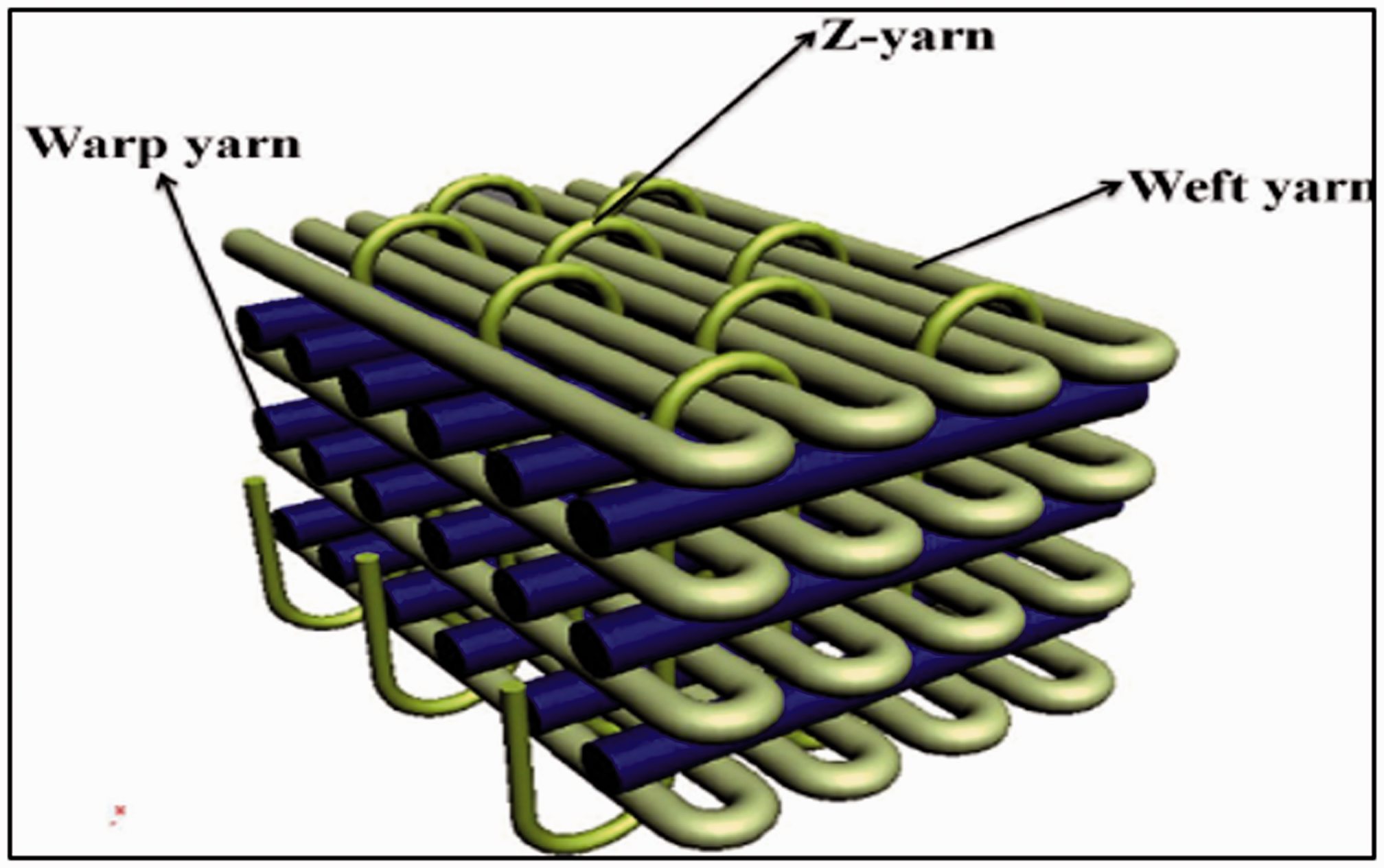
3D orthogonal woven fabric samples were developed in a customized rapier weaving machine, which is designed and equipped with multi-beam arrangement and modified take–up system. Kevlar and Zylon multifilament tows were used to weave the 3D woven orthogonal fabric. Kevlar yarn was obtained from Du–Pont company and Zylon was obtained from Toyobo company . The specifications of both yarns and 3D woven fabrics are given in Tables 1 and 2, respectively. The weave architecture of the 3D orthogonal structure produced for this project is shown in Figure 1. This 3D fabric consists of four layers with longitudinal warp yarns called stuffer warps, weft yarns in transverse direction, and Z yarns known as binder thread in through the thickness direction.
Specifications of yarns.

Specifications of 3 D orthogonal fabric.

Experimental procedure
For carrying out the low-velocity impact test, CEAST® FRACTOVIS PLUS model instrumented drop weight impact testing machine was used. A hemispherical impactor was made to drop from a height of 1.02 m at a velocity of 200 m min–1. The parameters of impactor or projectile are given in Table 3. These parameters were kept same in both the modelling methods as well as in actual experiment. The samples were prepared according to the ASTM D3763 standards with a size of 16 cm * 16 cm. The samples were fixated on the instrument by pneumatic clamping with a clamping force of 1500 N. The number of sample size is 5 for impact testing of fabric. The boundary conditions and the low velocity impact for both simulations and experiments on composite sample were defined as per the ASTM D3763 standard.
Projectile (Impactor) Parameters.

Modeling of 3D woven orthogonal structure
Texgen software was used to create the 3D model of orthogonal structure. In this system, the yarns behave as a solid volume, and modeling depends upon the different parameters of its constituents such as yarn cross-section, yarn path, and yarn surface. Primarily, Texgen was used here for developing the geometrical model of the orthogonal structure so that initial information of mechanical behavior of yarn was not required. The specifications of 3D model generated in Texgen are given in Table 4. The geometrical model of the 3D orthogonal weave structure produced on Texgen is shown in Figure 2.
Specifications of 3 D model generated in Texgen.


3 D orthogonal weave model developed in Texgen.
Analysis of 3D orthogonal model by FEM
The 3D model developed in Texgen has a default file format of .tg3. In order to further analyze this structure, firstly, it must be converted into a surface mesh in the Texgen platform. This will mesh the surface features of the 3D model and assign nodal points at the surface. The more the number of nodal points, the higher will be the surface mesh density, and more accurate results can be obtained upon analysis. The surface mesh model must be converted into an Abaqus Voxel file. This will enable the file script to be translated into the Abaqus environment for further analysis. Texgen and ABAQUS platform was used in combination because both are based on similar Python scripting interfaces. A unit cell was assumed to be a simple cubic; periodic boundary conditions were applied on the face of unit cell excluding the edges and at the edges excluding vertices [46]. The significance of the above boundary condition in conjunction with the constraint on rigid body translation and rotations which results in the 3D analysis of a fabric structure.
To simulate the impact problem, Abaqus/Explicit code was used with available VUMAT user subroutine for Hashin-3D material model. ‘Step Module’ Dynamic /Explicit solver was chosen to solve the problem because this Module helps to simulate the impact and deformation phenomenon. In the same module, the field and history output required can be specified. In CAE “Part Module”, the plate was modeled as “3D Deformable Solid” and the bullet was modeled as “3D Discrete Rigid”. An “8 noded linear brick 3D solid element C3D8R” was specified in the 'Mesh Module'. The “C3D8R” element was chosen for the Kevlar fabric as this kind of Mesh as has been shown to give more realistic simulations for ballistic impacts. The projectile was meshed uniformly by “3 node 3D triangular facet R3D3” discrete rigid elements. This triangular element was chosen for the projectile because it gives least error at the pointed edges of the projectile therefore enhancing the model accuracy.
These boundary conditions have been carefully chosen to give realistic approach to simulation for analyzing the impact behavior. Then, the properties of the selected material’s parameters for Kevlar 49 fabric were inputted through the “Materials” Tab. In ‘Assembly Module’, the Kevlar fabric and the ballistic projectile were assembled relative to each other and a gap of 0.5 mm was maintained to apply Node to Face Contact between the projectile and plate surface. The duration of impact was considered to be 0.0003 sec in all the cases. The contact between the projectile and fabric was defined in the ‘Interaction Module’. The boundary conditions were defined in the ‘Load Module', and it was assumed that all the four edges of the Kevlar were fixed and the initial velocity of 200 m/min was assigned to the bullet in the predefined field condition. Optimization module was used to create an optimization task which can be used to optimize the topology or shape of the model and given a set of objectives and restrictions. The final step for performing the simulation is the Job module. It is used to create and manage analysis jobs and to view a basic plot of the analysis results. It is also used to create and manage adaptivity analyses and co-executions.
Steps for impact simulation on 3D weave structure are shown in flowchart in Figure 3. 3D model of orthogonal fabric developed in Texgen was exported to Abaqus platform as shown in Figure 4(a). Modeling of the fabric was done by using the Pattern option in Assembly Module and unit cell patterning shown in Figure 4(b). Hemispherical impactor shown in Figure 4(c) of given specifications was used for simulating the low velocity impact on the fabric. The outer hemispherical surface of the fabric is stored as an interacting surface as well. Figure 4(d) shows the assembly of impactor and fabric created by assembly module by positioning the impactor vertically top of the 3D woven fabric at a specified distance in a global coordinate system. The positions are as such that the two interacting surfaces face one another, and the axis of the impactor passes through the center of the fabric. Boundary conditions on 3D weave structure are shown in Figure 4(e) and (f) shows the meshed structure of the fabric and the impactor, after that this structure was used for finite element modeling.
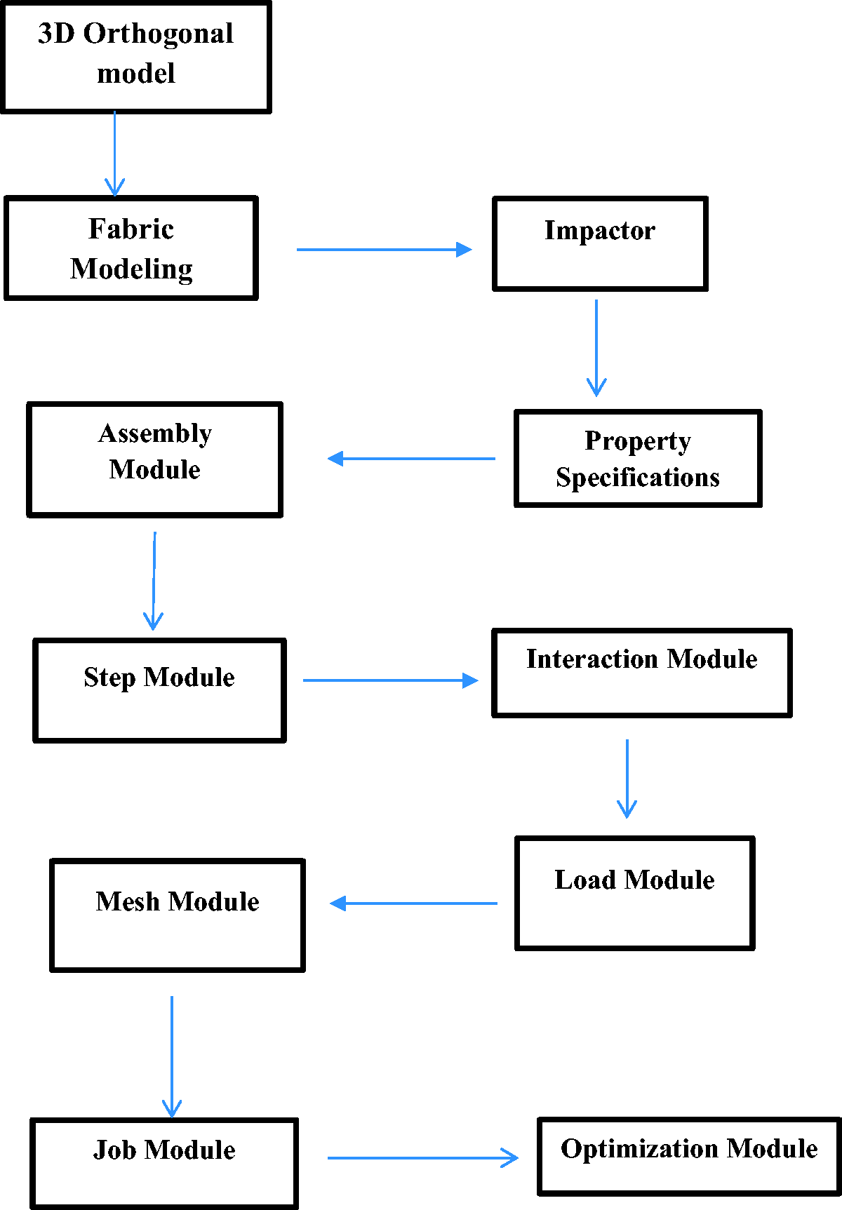
Flowchart of FEM modeling in Abaqus platform.

Modeling of 3 D structure in Abaqus (a) Imported 3 D weave fabric in ABAQUS (b) Patterning of unit cell (c) Creation of hemispherical impact in ABAQUS (d) Assembly of Impactor and Fabric (e) Boundary conditions on 3 D weave structure (f) Meshed structure of fabric and impactor.
Analytical model for 3D orthogonal structure
Modeling approach
In many technical applications, textile materials are subjected to loading or straining rates that may be much greater in magnitude than the regular household applications of these materials. One of the major forces these technical textiles are exposed to is the ballistic force. The primary energy absorbing mechanisms during ballistic impact are the kinetic energy absorbed due to the tensile failure of the primary yarns and the energy absorbed due to elastic deformation of the primary and secondary yarn as demonstrated in Figure 5 [22]. An analytical model was carried out to find the energy absorbed by the fabric during the event of impact.

Analytical model methodology.
An analytical model was established to study the ballistic impact onto multiple layered woven fabric panels by projectile, based on ballistic impact of single textile yarns. Basic kinematics equations, conservation principle and stress-strain relations were used. The yarns are divided into primary yarns and secondary yarns. The direct impact received by primary yarns from the projectile provides the resistance to projectile, which results in its deceleration. In ballistic panel, the impact is transmitted to the secondary yarns due to the crossover points between the weft and warp yarns involved in the fabric. The energy absorbed by each yarn during breakage is calculated and multiplied to give the energy absorbed by breakage for 3D fabric. For determination of energy absorbed due to deformation, firstly the maximum deformation is calculated for last layer of yarns and correspondingly each layer deformation is evaluated. Knowing the strain in each layer, the strain energy is calculated for each yarn and multiplied to get the complete value of layers. Similarly, the deformation energy for secondary yarns is evaluated and are summed up to get the whole value i.e. impact energy for Kevlar and Zylon.
Step by step derivation of impact energy absorbed by fabric

Schematic representation of a model.

Illustration of area under the impact of projectile.

Deformation in the primary yarn.

Illustration of deformation in secondary yarns.

Forces on the projectile.

F =


EPI and PPI are ends per inch and picks per inch respectively,
[ ] denotes the greatest integer function

Where, A = yarn cross section, Tex = yarn fineness,
ϕ = Fibre volume fraction (FVF)

Eabs = No of yarns undergoing breakage * Energy absorbed by single yarn

Step 17: Maximum deformation of secondary yarns
The deformation of the secondary yarns is calculated with the assumption that the deformation values are linearly dependent on the distance from the boundary, i.e. the yarns causing the deformation forms a triangular section as shown in Figure 9.
Therefore, summing the individual elastic energies absorbed for each yarn.
The following summation given in equation (10) can be used to compute the total value of absorbed strain energy by the secondary yarns [22].


Where n is total number of deformed(secondary) yarns and r is radius of projectile.
Step 18: Calculating total energy absorbed
The total energy absorbed by the yarns due to the impact can be calculated as the sum of the energy required by the primary yarns to break and the deformation energy stored by the slipped primary and the secondary yarns.
Results and discussion
Evaluation of FEM analysis
The failure and energy dissipation mechanism of Kevlar fabric subjected to low velocity impact was numerically investigated via FEM by using ABAQUS platform. After solving the problem Abaqus/Explicit generates, output database file (*.ODB), contains the results from the analysis. The output database file (*.ODB) is the binary output file that will be read during post-processing to view graphical results. Output database files in Abaqus/CAE loads in the ‘Visualization module’ and allows viewing a graphical representation of the outputs. In Abaqus postprocessor, it is possible to draw the output data in the form of X-Y plot. The variables can be specified from field output and history output, assigned in ‘Step module’. In this study, the Energy absorbed versus time was plotted for the above simulation.
Figure 11 shows simulation of the 3D model of Kevlar fabric in which projectile impacted on the fabric. The graph obtained between energy and time from FEM analysis is shown in Figure 12 and the total energy absorbed for Kevlar fabric calculated by FEM was 52.3 J. In Figure 12, from 0.1 to 0.15 unit of time the curve is flat because initially, from the very beginning when the simulation has started for 0.1 unit of time while projectile was travelling as it still has not contacted yet till that period with the target, 3D fabric. It may be seen from the graph that the relationship is not perfectly linear, rather the curve slightly bends toward the strain axis with increase in strain.

Simulation of Kevlar 3 D model in ABAQUS.

Energy absorbed by Kevlar fabric versus time.
Experimental result
3D orthogonal fabrics were made of Kevlar and Zylon, and both were tested for the impact as per the ASTM D3763 method. It has been found that from previous researches that 3D orthogonal structures have better impact properties than their counter parts. It has been proven from countless studies for 2D fabric and their laminates that in the event of a transverse impact, the energy absorption rate increases monotonically with fiber modulus rather varying strain energy rate, projectile mass, and momentum [48,49]. David et al. mentioned in their research by conducting significant numbers of computational modeling on ballistic penetration resistance of laminated textile composites due to the tendency of the low breaking strain of high modulus materials and tend to show low impact resistance. In contrast, the rate of energy absorption of laminated panels increases with the fiber modulus [48,50]. A numerical approach was presented by Freeston et al. [48,51] where it exhibited that while a 2D woven fabric exposed to ballistic impact, the maximum yarn strain happens at the point of contact and goes off along the path of the yarn away from that contact point. Different fiber attributes such as linear density, young modulus, and strength as well as various projectile features, e.g., mass, shape, and velocity of the impactor, have been considered by Termonia et al. [52] in their experimental research on the impact resistance of 2D woven fabric during an impact incident. They stated that some noticeable features get affected by the yarn slippage through clamps. Lekhani et al. [53] has showed internal geometry of uneven hollow structures with honeycomb core and skin, which have been used for a variety of engineering applications such as lightweight structural composites material. It has been found that different cell geometries of honeycomb structures and various shapes of even sandwich strcutures [54] such as rectangular, triangular, and trapezoidal have influence in mechanical attributes of the fabric and its constituent composites.
From the experimental results, it can be seen from the Figure 13 that although both the fabrics are produced with nearly same aerial density, identical number of layers as well as same no. of yarns in all directions, and same fibre volume fraction (approx.), Zylon (82.178 joule) absorbs 38% more energy than Kevlar (43.86 joule) during the impact test. It was evident from previous researches that yarn characteristics play a pivotal role in energy absorption while impactor comes to a contact with the fabric under ballistic impact [52]. From the specification of both yarn in Table 2, it shows that Zylon has nearly 53% higher modulus than its counterpart, Kevlar. Therefore, the fabric made of Zylon exhibits higher energy absorbing tendency than Kevlar.

Fabric samples after impact (a) Kevlar (b) Zylon.
Validation of results obtained through analytical model and numerical model
Comparison of numerical model and experimental results
The numerical modeling was carried out for the fabric made of Kevlar to compute the impact energy, and the impact energy was determined on low-velocity (200 m/min) by the tub impact method (drop weight impact tester). Experimental value is compared with model result by plotting a bar chart shown in Figure 14. The diagram reveals a satisfactory correlation between the numerical and experimental results with a maximum error of 19%. The Error% in prediction was calculated from the equation (14)

Numerical model and experimental results of impact energy for Kevlar fibre.
The results obtained using simulation overestimated the impact energy absorbed by the 3D fabric during impact by the projectile. The possible explanations for this deviation are: The software is considered a linear stress-strain curve before the yield point, which is not entirely linear and slightly bends toward the strain axis with increased strain. The yarns do not entirely follow the parameters and properties given to the yarns while performing the simulation operation.
Comparison of analytical model and experimental results
The total impact energy obtained from the analytical and experimental results is depicted in Figure 15 for validation purposes. The impact energy results show that the predicted value gives a close approximation of the experimental result for the 3D woven orthogonal structure of Kevlar and Zylon with a maximum error of 16%. It is also illustrated from the results that Zylon based 3D fabric gives higher impact energy than its Kevlar counterpart.

Predicted and experimental results of impact energy for different fibers.
While trying to understand the reason for this deviation, it is realized that the approach used for the calculation of the impact energy for the 3D fabric is reasonably conservative. Given the analysis, the following facts are attributed to the error obtained in determining the impact energy value by analytical modeling. The losses in the form of heat generation due to various frictional contacts, such as fiber to fiber, fiber to projectile have not been taken into consideration. Differences may arise due to different flexural rigidities of the various fibers leading to different propagation of the deformation to secondary yarns. The yarns in Z direction may be absorbing some of the energy through deformation which has not been accounted for. There may be slippage of yarn held between the plates leading to lower strain of the yarn than calculated.
However, keeping in view the flexibility of textile material and probability of irregular geometry of the 3D woven fabrics in which three constituent yarns are disposed of without proper mutual interlacement, the deviation of predicted value to the extent of 16% from the experimental value may be considered reasonably acceptable.
Conclusions
Impact energy absorption of 3D woven orthogonal fabrics produced from Kevlar and Zylon tows were determined by numerical and analytical approaches. Although the analytical model was developed meticulously in several steps, the mathematics involved in heat generation losses due to various frictional contacts, such as fiber to fiber, and fiber to the projectile was neglected. The numerical modeling performed through simulation on Abaqus software is based on mathematical coding. The predicted results obtained from both the models were compared with the experimental values. The estimated error in both models falls between 16–19% due to some unavoidable constraints attributed to textile material’s inherent characteristics and 3D woven orthogonal structure. However, the deviations in predicted values are considered acceptable, considering the textile fiber’s flexible nature.
The present scope of this research was limited to a structure and a particular type of 3D fabric. The study can be taken forward by studying the impact characteristics of various models with varied weave architectures by investigating the effects of various geometric parameters such as yarn spacing, fabric thickness, yarn width, and fiber volume fraction. Each of these models could also evaluate the differences in the impact energy of 2D and 3D fabrics, and among the various structures of 3D fabrics.
Footnotes
Declaration of conflicting interests
The author(s) declared no potential conflict of interest with respect to the research, authorship, and/or publication of this article.
Funding
The author(s) disclosed receipt of the following financial support for the research, authorship, and/or publication of this article: The project team sincerely acknowledges the Ministry of Textiles, Government of India for sponsoring this project to Focus Incubation Centre of 3D Fabric and Structural Composite.