
Abstract
The optimization of process parameters such as applied voltage, orifice diameter, solvent system, and solvent ratio for electrospinning of neat polymers, polylactic acid (PLA) and poly (є-caprolactone) (PCL), to obtain uniform, randomly oriented nanofibers with minimum diameter variation and beaded structures has been critically discussed. The paper focuses on establishing a sequential optimization technique for arriving at a common set of electrospinning process parameters for individual polymers, such as, applied voltages, orifice diameters, solvent mixtures, solvent ratios, to be used in the fabrication of electrospun nanofibrous mats (ENMs) of blended polymers. In this study, the effect of variation of applied voltages, orifice diameters, solvent mixtures, solvent ratios, PLA/PCL blending ratios, solution concentration of blends and flow rate were reported via morphological analysis of electrospun nanofibers. The set of optimal process parameters obtained for both PLA and PCL were adopted for the fabrication of ENMs based on the PLA/PCL blends. The paper further deliberates on the physical performance of PLA/PCL based ENMs in acidic, basic and neutral release media. Thus, the study establishes a hierarchical processing optimization route for designing blended ENMs by following a set of variable electrospinning process parameters.
Introduction
Electrospinning is a versatile and cost-effective technique for fabricating electrospun nanofibrous mats (ENMs) embracing long and continuous nano-fibers, obtained on application of electrostatic forces on polymer solutions. Over the years, electrospinning of polymer solutions for the fabrication of nanofibrous membranes has attracted both academia and industry. In the present scenario, electrospun nanofibers are being used in the fabrication of tissue scaffolds, drug carriers, filters, protective apparel, sensors and nanocomposites [1–12]. The electrospinning of biodegradable polymers is currently preponderating, as the fabricated ENMs mimic the structural morphology of natural extracellular matrix (ECM) [13–15]. Thus, several biodegradable polyesters have been broadly studied, e.g., polylactic acid (PLA), polyglycolic acid (PGA), poly (ε- caprolactone) (PCL), polyhydroxy butyrate (PHB), and poly (3-hydroxy valerate) for the fabrication of biomedical devices [16,17]. The two well-known biodegradable polymers, polylactide (PLA) and poly (ε- caprolactone) (PCL) are used in this study. PLA is one of the most promising biopolymers constituting biocompatible nature, high modulus and decent strength. However, the intrinsic brittleness of PLA brings about poor impact and tear resistance which impedes its use in numerous applications. Thus, PCL, being biodegradable and flexible, is often incorporated in stiff PLA matrix, in order to prevent brittle failure thereby enhancing its ductility, pliability and load transfer efficiency. Reportedly, PLA and PCL based blends are immiscible thermodynamically, and thus exhibit phase separation and poor interaction at the interface [18,19]. Thus, the fabrication of electrospun nanofibers provides special aspect ratio to the continuous fibers as the fiber diameter is in nano-scale, thereby enhancing their interfacial interactions, dispersive homogeneity and biodegradability [18–21].
To fulfill the application requirements and to attain desirable properties, the fiber diameter, morphology, porosity, size, and various mechanical properties need to be optimized. The influence of fiber diameter and morphology on thermal, microstructural, mechanical and viscoelastic properties of PLA/PCL based ENMs have already been reported [19]. Furthermore, modeling nanostructured materials by dispersing nanofibers into a polymer matrix, to enhance their interfacial load transfer efficiency and high aspect ratio present an astounding contribution towards smart and miniaturized technology. A schematic designing and fabrication of electrospun nanofiber incorporated PLA/PCL based engineered composite patches and their morphological, microstructural and mechanical properties have also been reported [18]. Thus, the fabrication of biodegradable polymer-based ENMs has emerged out to be a paradigm that has exceptional potential in the fabrication of biomedical devices which act as crucial prodigy materials [5,22–25].
Electrospinning of polymer solutions is usually accompanied by optimization of numerous process parameters such as applied voltage, orifice diameter, receiving distance, solution concentration, solvent system, and flow rate which govern the surface morphology, diameter, crystallinity and various physico-mechanical properties of fabricated electrospun fibers. The electrospinning solution conductivity, surface tension, and viscosity directly influence the electrospun fiber morphology thereby, modulating their mechanical properties. Lu et al. [26] have successfully optimized some electrospinning process parameters for PLA/PCL blends using DCM/DMF as the solvent mixture. Nevertheless, abundant knowledge and information have been reported for the fabrication of lone polymer-based ENMs [27–32]. However, a standard experimental technique needs to be introduced for schematic optimization of fiber diameter and morphology of blended ENMs.
Considering the above facts, this paper focuses on initial optimization of electrospinning process parameters for individual PLA and PCL based ENMs, by studying the influence of variation in applied voltage, orifice diameter, solvent system and solvent ratios on the morphology of ENMs, to obtain electrospun fibers with minimal bead defects, average fiber diameter, and diameter variation. So far, the papers published have not reported any schematic route to determine the optimum process parameters for the fabrication of blended ENMs. Thus, the study aims at determining a common set of optimized process parameters for individual PLA and PCL based ENMs, to be used for the fabrication of randomly oriented PLA/PCL blended ENMs. Thus, to design PLA/PCL blended ENMs with average fiber diameter in nanoscale and minimum bead defects, the influence of variation in PLA/PCL blending ratio, solution concentration and flow rate on the morphology of blended fibers were studied. As the blended ENMs are known to exhibit enhanced drug release rate compared to lone polymer-based ENMs [33]. The paper also discusses the physical performance of PLA and PCL based ENMs, in acidic, basic and neutral release media, as they act as potential candidates for the fabrication of various biomedical devices.
Experimental
Materials
Injection moulding grade (3052 D) of PLA with a number average molecular weight of 1,16,000 g mol−1 and PCL (Capa® 6800) with a number average molecular weight of 80,000 g mol−1, were purchased from NatureWorks, USA, and Perstorp, UK respectively. Chloroform (CF), Dimethylformamide (DMF) and Dichloromethane (DCM) of AR grade, purchased from Fisher Scientific, India, were used to prepare electrospinning solutions. PLA and PCL were vacuum dried before use.
Fabrication of ENMs
The ENMs were prepared using the horizontal set-up of the Electro-spinning machine (Super-ES-2, E-spin Nanotech Pvt. Ltd., India) as shown in Figure 1. The PLA and PCL based electrospinning solutions were loaded in a 5 ml syringe with a blunt needle (metal capillary) attached to it. The syringe was then fixed onto a syringe pump to regulate the flow of electrospinning solution. The receiving distance of ∼ 15 cm between the tip of the capillary and the drum collector and the drum speed of ∼ 700 rpm were kept constant throughout the study [34]. The electrospun fibers were produced when a high voltage supply, sufficient to generate a charged jet, was applied at the tip of the metal capillary. The fibers were deposited on an aluminium foil placed over the grounded drum collector which was allowed to move in both x- and y-direction as shown in Figure 1. The entire assembly was placed in a chamber with relative humidity ∼ 40% and a temperature of ∼ 25°C. Further, the electrospun fibers were vacuum dried at ∼ 30°C for 48 h, to remove any residual solvent and were stored in a desiccator.

Schematic of the electrospinning set-up.
Variation in applied voltage
PLA and PCL (∼10 wt.%) electrospinning solutions were prepared using a CF and DMF solvent mixture in ratio 4:1 v/v. The electrospinning solutions were loaded into a syringe with a needle having ∼ 0.5 mm tip diameter and ∼ 1.5" metal capillary attached to it. The flow rate of ∼ 0.5 ml/h and electrospinning duration of ∼ 30 minutes were kept constant with a variation in positive voltage from ∼ 16 kV to ∼ 22 kV to study its effect on fiber morphology and distribution.
Variation in orifice diameter
The neat PLA and PCL based fibers were fabricated using needles with varied orifice (tip) diameter ranging from ∼ 0.9 to ∼ 0.4 mm for ∼ 30 minutes. The flow rate of ∼ 0.5 ml/h was kept constant. Here, electrospun fibers were fabricated from ∼ 10 wt.% electrospinning solutions prepared using CF/DMF in the ratio 4:1 v/v at ∼ 20 kV.
Variation in solvent system
PLA and PCL based fibers were electrospun using ∼10 wt. % solution for two different combinations of solvents, which are CF/DMF (4:1) and DCM/DMF (4:1), at ∼ 20 kV applied voltage. The electrospinning was performed using ∼ 0.5 mm needle tip diameter and ∼ 0.5 ml/h flow rate for ∼ 30 minutes.
Variation in solvent mixture
The electrospun fibers of PLA and PCL were fabricated from ∼ 10 wt.% solution prepared using different ratios of CF/DMF (100/0, 90/10, 80/20, 70/30 and 60/40) solvent mixtures. Fibers were electrospun by keeping the orifice diameter of ∼ 0.5 mm, an applied voltage of ∼ 20 kV and a flow rate of ∼ 0.5 ml/h constant for ∼ 30 minutes.
Variation in PLA/PCL blending ratios
PLA and PCL based blended electrospun nanofibers, with varying PLA/PCL blending ratios (30/70, 50/50 and 70/30 w/w) were fabricated from ∼10 wt.% solution prepared using CF/DMF (4:1) solvent mixtures at ∼ 20 kV. Electrospinning was performed keeping the orifice diameter of ∼ 0.5 mm and a flow rate of ∼ 0.5 ml/h constant for ∼ 30 minutes.
Variation in solution concentration of the blend
PLA/PCL blended (70:30 w/w) electrospun nanofibers were fabricated from ∼ 8, ∼ 10 and ∼ 12 wt.% solutions which were prepared using CF/DMF (4:1) solvent mixtures at ∼ 20 kV applied voltage. Fibers were electrospun by keeping the orifice diameter of ∼ 0.5 mm and a flow rate of ∼ 0.5 ml/h constant for ∼ 30 minutes.
Variation in flow rate
A comparative analysis of PLA, PCL and PLA/PCL blended (30:70, 50:50 and 70:30 w/w) electrospun fibers was performed by varying the flow rate between ∼ 0.5 ml/h and ∼ 4 ml/h. Fibers were electrospun from ∼10 wt. % solution prepared using CF/DMF (4:1) solvent mixture and by keeping the orifice diameter of ∼ 0.5 mm and applied voltage of ∼ 20 kV constant for ∼ 30 minutes.
Electrospinning solution characterization
Anton Paar (MCR 702) Twin Drive rheometer equipped with measuring cylinder (B-CC20 with 20 mm diameter) geometry and measuring cup (C-CC20) geometry was used to study the rheological attributes of polymer solutions. The characterization of samples was performed at the shear rate ranging from 0.1 to 1000 s−1 (∼25 °C, 1 Hz).
Oakton (CON 700) conductivity meter equipped with a glass electrode (cell constant, K = 1) was used to measure the electrical conductivities of polymer solutions at ∼ 25 °C. The solution conductivities reported as an average of at least five consecutive measurements.
Morphological characterization
The surface morphologies of ENMs were studied using Scanning Electron Microscopy (SEM) and Atomic Force Microscopy (AFM). SEM analysis was performed using Zeiss EVO 50 and the surface of samples were gold coated using 20 mA current supply for 2 minutes. Micrographs were recorded by varying the working distance at required magnification to obtain a focussed image using ∼ 20 kV accelerating voltage. Atomic Force Microscopy (AFM) was also used to analyze the phase contrast in surface morphologies of ENMs. AFM analysis was performed, using tapping mode for ENMs, with a hpAFM by NanoMagnetics instrument.
Physical performance evaluation (in-vitro)
The degree of swelling and weight loss for PLA, PCL and PLA/PCL (70/30 w/w) blended ENMs were evaluated in acidic (pH = 4), basic (pH = 9.2) and neutral (pH = 7) media for 48 h using equations (1) and (2), respectively. Mi, Ms and Md in equations (1) and (2) represent the initial weight of samples, weight of swollen samples and dried samples respectively. The set-up was placed in an incubator shaker at 200 rpm for 48 h at 37 °C. The weight of swollen samples was recorded after drip-drying using filter paper and for dried samples, the weight was recorded after oven-drying at ∼ 40 °C for ∼ 48 h.


The samples were prepared in triplicates and weights of swollen samples and dried samples were measured at periodic intervals for 48 h and an average was reported. The variation in fiber diameter after 48 h was studied using SEM.
Results and discussion
The electrospinning of the neat polymers and blends have been systematically carried out while introducing variation in seven operating parameters and a hierarchical optimization route is followed through by resorting to conducting experiments at one-variable-at-a-time (OVAT) approach.
Effect of applied voltage on the output response
Microscopic images of PLA and PCL based electrospun fibers indicate a decrease in beaded morphologies with an increase in fiber deposition on increasing the voltage up to ∼ 20 kV, as shown in Figure 2. The duration of electrospinning was kept constant (∼30 min) for comparative analysis. The increase in fiber deposition on increasing the applied voltage is attributed to the increased release of electrospinnable fluid into the jet at higher applied voltages. Furthermore, the average fiber diameter distribution curve represents a minimum for average fiber-diameter variation at ∼ 20 kV for both PLA and PCL based ENMs as shown in Figure 3. However, an increase in beaded morphologies with a decrease in fiber deposition was observed on further increasing the applied voltages beyond ∼ 20 kV as shown in Figure 2(d) and (h). Sill et al. [2] reported the influence of applied voltage on the shape of the pendant drop and Taylor cone formation at the capillary tip. Thus, the increase in bead defects, at applied voltages greater than ∼ 20 kV, may be attributed to the increase in force required to eject the charged jet. This results in the inability of stable Taylor cone formation thereby affecting the continuity of charged jet. As a result, ∼ 20 kV was considered to be an optimum value of applied voltage for the fabrication of PLA and PCL based electrospun fibers with minimum bead defects and more uniform fiber diameter and diameter variation.

SEM images of electrospun PLA (a–d) and PCL (e–h) fibers at ∼16 kV, ∼18 kV, ∼20 kV and ∼22 kV applied voltages respectively.

Variation in average fiber diameter with applied voltage for electrospun PLA and PCL fibers.
Variation in needle diameter
A decrease in bead defects with a decrease in orifice diameter of the metal capillary was observed for both PLA and PCL based electrospun fibers as shown in Figure 4. Minimum average electrospun fiber diameter and variation were observed for both PLA and PCL based electrospun fibers fabricated using metal capillary with ∼ 0.5 mm orifice diameter as shown in Figure 5. On further decreasing the orifice diameter to ∼ 0.4 mm, the electrospun fiber deposition was observed to decrease with an increase in fiber diameter variation and bead defects. This may be attributed to the clogging of the metal capillary on decreasing the orifice diameter resulting in difficulty in maintaining the continuity of jet. However, for higher orifice diameter ∼ 0.9 mm, extraordinarily high fiber diameter variations were observed for both PLA and PCL based electrospun nanofibers. This is due to the fluid being ejected directly into the jet without the formation of a stable Taylor cone. Furthermore, the bead defects arise due to instability of jet initiation, which is more for less viscous (low molecular weight) PCL solution and results in difficulty in maintaining straight jet which subsequently induces more bending instability. Thus, physically entangled fibers are obtained for PCL with more bead defects compared to high molecular weight PLA solution. As a result, ∼ 0.5 mm was considered to be an optimum value of orifice diameter for the fabrication of both PLA/PCL based ENMs in the subsequent sections.

(a to d) SEM images for electrospun PLA fibers and (e to h) for electrospun PCL fibers obtained for needle tip diameters ∼ 0.9 mm, ∼ 0.7 mm, ∼ 0.5 mm and ∼ 0.4 mm, respectively.
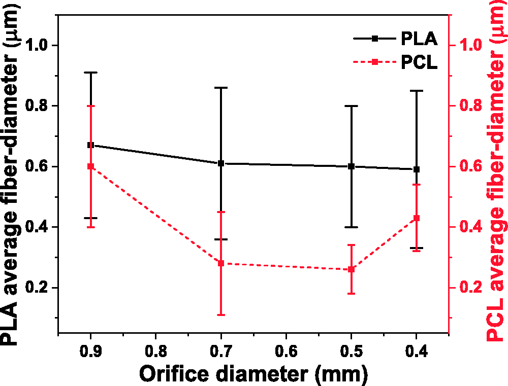
Variation in PLA and PCL average fiber diameter with orifice diameter.
Variation in solvent system
SEM images of PLA and PCL based electrospun fibers fabricated from electrospinning solutions prepared using CF/DMF and DCM/DMF (4:1) solvent systems is shown in Figure 6(a) to (d). Microscopic images revealed a decrease in average electrospun fiber diameter and variation with more uniform fiber deposition obtained for CF/DMF system compared to DCM/DMF system, for both PLA and PCL based electrospun fibers, as shown in Figure 6(e). This may be attributed to high dielectric constant and low boiling point of DCM (b.p.= 39.6 °C and dielectric constant = 8.9 at 20 °C) compared to CF (b.p.= 61.2 °C and dielectric constant = 4.8 at 20 °C). For CF/DMF system it is believed that jet solidification is comparatively slower which allows the jet elongation and stretching to continue longer than DCM/DMF solvent system. Thus, CF/DMF based electrospinning solutions resulted in the fabrication of comparatively more uniform fiber surface morphology with minimal average fiber diameter and variation and are thus used for fabrication of PLA/PCL based ENMs in the subsequent sections.
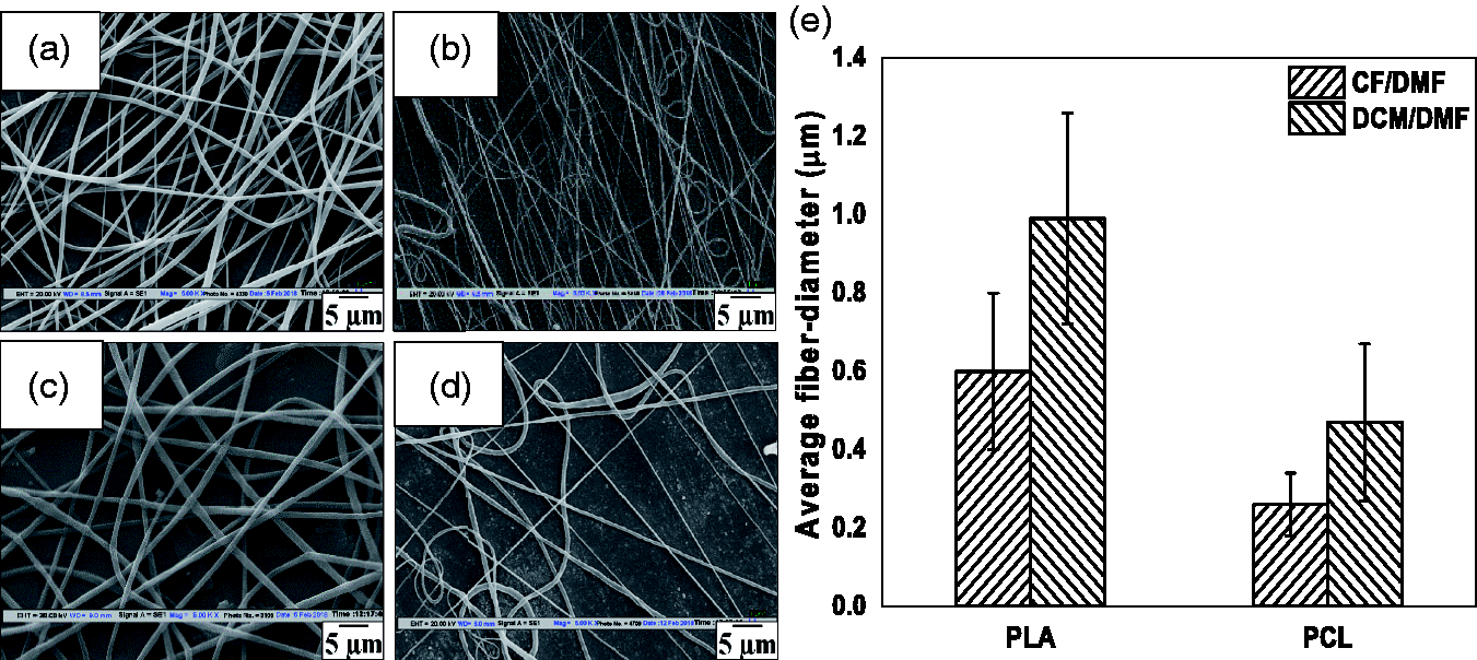
SEM images for PLA and PCL based electrospun fibers fabricated using electrospinning solutions prepared from (a and b) CF/DMF and (c and d) DCM/DMF solvent systems respectively; (e) variation in average fiber diameter of electrospun PLA and PCL fibers for CF/DMF and DCM/DMF systems.
Variation in solvent ratios
Rheological studies of PLA and PCL based electrospinning solutions in various CF/DMF solvent mixtures is shown in Figure 7. It was observed that an increase in DMF (poor solvent, b.p. =153°C and dielectric constant = 38.3 at 20 °C) content in solvent mixtures results in a decrease in solution viscosity of PCL based electrospinning solutions. This may be attributed to the comparatively better solubility of PCL in DMF [35]. However, for PLA based electrospinning solutions, solution viscosity was observed to increase with DMF content in the electrospinning solutions. The increase in solution viscosity for PLA based electrospinning solutions may be attributed to the poor solubility of PLA in DMF [36]. Furthermore, CF/DMF (80/20 v/v) solvent mixture exhibits similar values of solution viscosity at a shear rate of 101 s−1 as shown in Figure 7. The microscopic images for PLA and PCL based electrospun fibers fabricated using various CF/DMF solvent mixtures are shown in Figure 8. An increase in CF (good solvent, b.p.= 62 °C and dielectric constant = 4.8 at 20 °C) content in solvent mixtures tends to alter the solvent volatility of electrospinning solutions. This may be attributed to the comparatively lower boiling point of CF than DMF and thus leading to the formation of porous surface morphologies of PLA based electrospun fibers, due to the differential evaporation of the solvents of electrospinning solutions [28], as indicated by the SEM images shown in Figure 8. A further decrease in CF content in electrospinning solutions and a simultaneous increase in DMF content resulted in a subsequent decrease in solution volatility and thus poor fiber surface morphologies with the formation of fused fibers at the interfaces (CF/DMF = 70/30 and 60/40 v/v solution mixture). This is attributed to the comparatively high boiling point of DMF which affects the ability of the fibers to dry before reaching the collector and may result in the formation of bead defects.

Rheological properties of (a) PLA, (b) PCL based electrospinning solutions and (c) variation in solution viscosity at a shear rate of 10 s−1 for various CF/DMF solvent ratios.
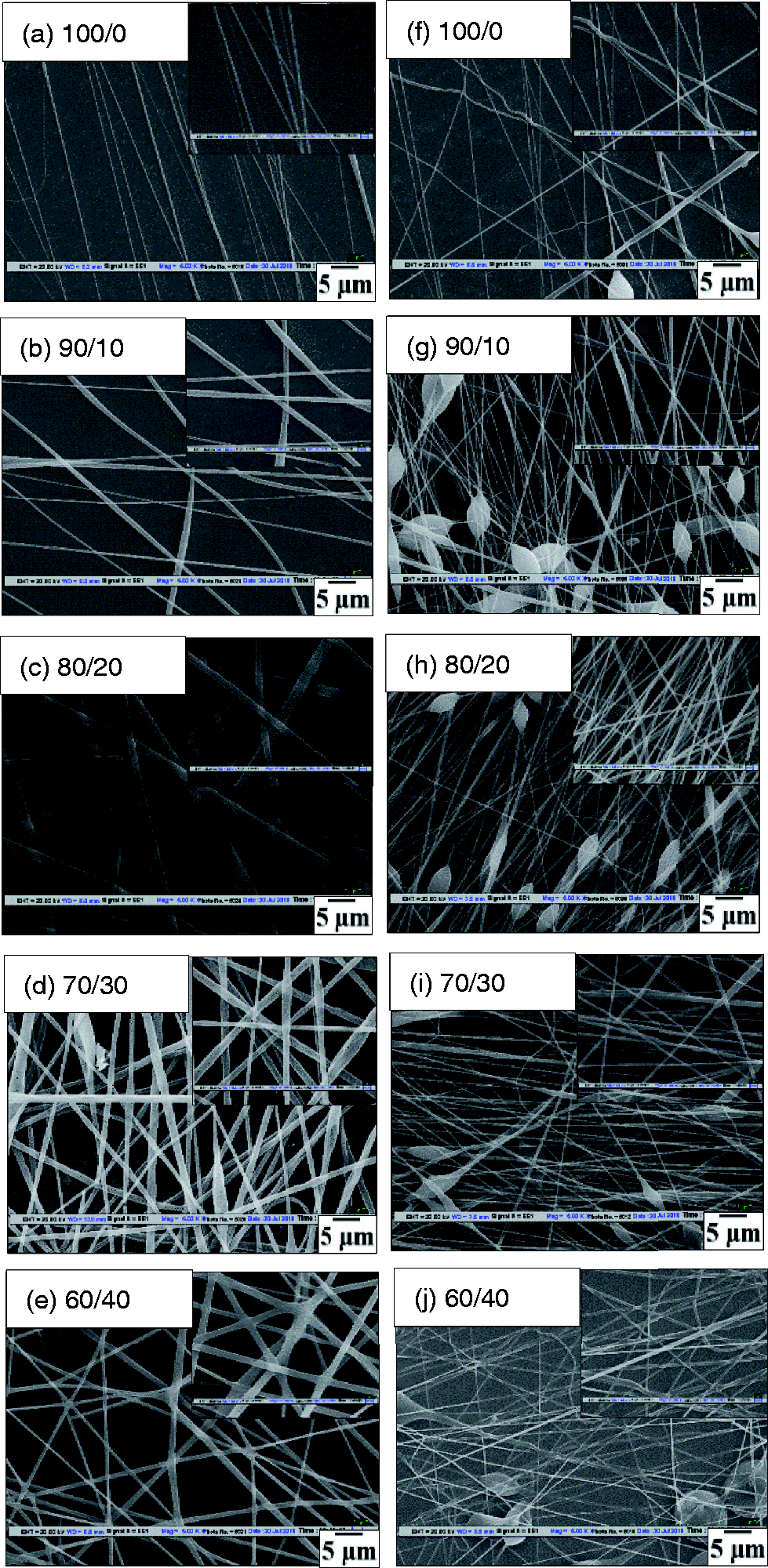
(a to e) SEM images of PLA based electrospun fibers (f to j) PCL based electrospun fibers for 100/0, 90/10, 80/20, 70/30, 60/40 ratios of CF/DMF solvent mixture.
In addition, an increase in DMF content results in a subsequent increase in electrical conductivity of PLA and PCL based electrospinning solutions as shown in Figure 9. PLA and PCL based electrospinning solutions exhibit similar electrical conductivity up to ∼ 20% (v/v) DMF content. However, a further increase in DMF content resulted in comparatively high electrical conductivity of PLA based electrospinning solutions compared to PCL. Furthermore, variation in average electrospun fiber diameter and diameter variation of PLA and PCL systems with electrical conductivity of electrospinning solutions is shown in Figure 10. For, PLA average fiber diameter variation was observed to decrease with the increase in DMF content up to ∼ 20% (v/v). However, on further increasing the DMF content the average electrospun fiber diameter and variation were observed to increase due to the formation of fused and non-uniform surface morphologies amongst electrospun fibers. Similarly, for PCL based electrospinning solutions, minimum diameter variation was observed for electrospun fibers fabricated using electrospinning solutions comprising of ∼ 20% (v/v) DMF content as shown in Figure 10. In addition, CF/DMF (80/20 v/v) solvent mixture-based electrospinning solutions resulted in the fabrication of more uniform fiber surface morphologies, with maximum deposition and comparatively minimum bead defects for both PLA and PCL based electrospun fibers. Furthermore, PLA based electrospun fibers were observed to exhibit a comparatively higher average fiber diameter than PCL. The higher molecular weight of PLA compared to PCL provides relatively higher solution viscosity to the electrospinning solutions, thereby, enhancing their ability to maintain the continuity of charged jet. As a result, minimum bead defects are obtained for neat PLA based fibers compared to PCL. Thus, CF/DMF (80/20 v/v) is considered to be the optimum solution mixture which results in minimum average fiber diameter, diameter variation and uniform surface morphologies for both PLA and PCL based electrospun fibers and is thus used for fabrication of PLA/PCL blended ENMs in subsequent sections.

Variation in electrical conductivity for PLA, PCL (∼10 wt. %) and polymer-free solution mixtures with the increase in DMF content.
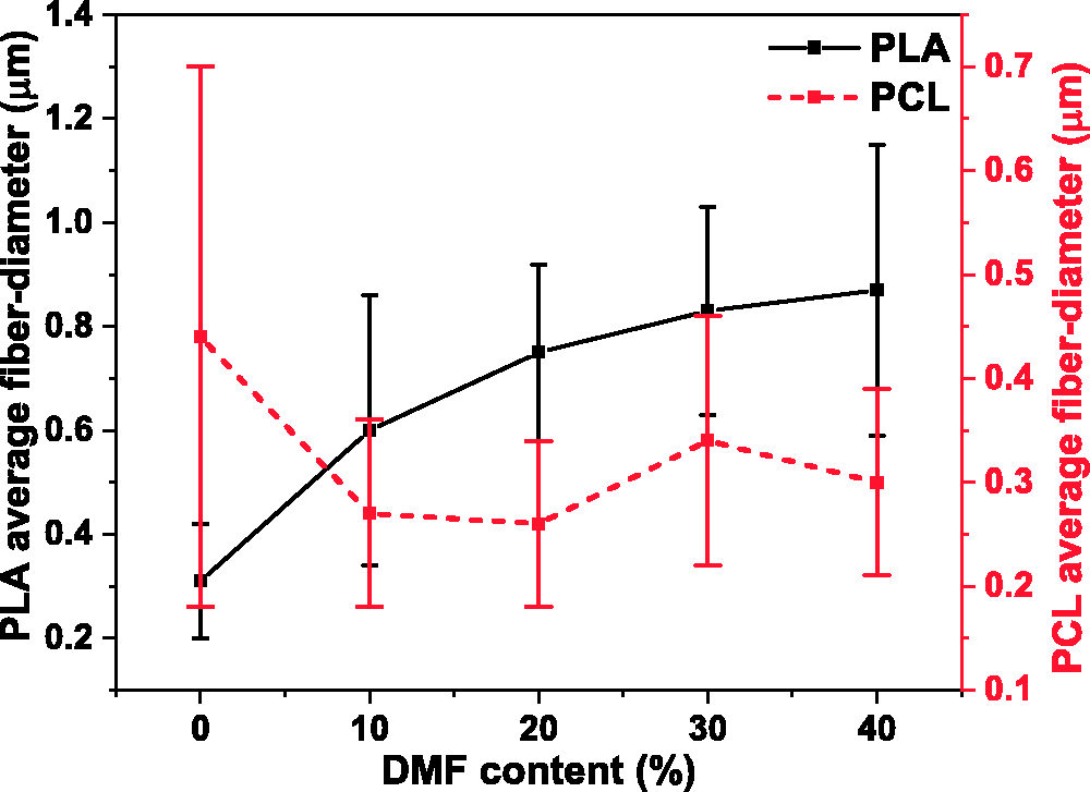
Variation of PLA and PCL average fiber diameter with respect to DMF content in various CF/DMF solvent ratios.
Variation in PLA/PCL blending ratios
The optimized process parameters which resulted in the production of uniform, bead free ENMs for both polymers (PLA and PCL) were used for the electrospinning solution preparation and fabrication of PLA/PCL based blended ENMs. ENMs were prepared for three different PLA/PCL blending ratios (30/70, 50/50 and 70/30 w/w). Microscopic images for 30/70, 50/50 and 70/30 (w/w) PLA/PCL blended ENMs are shown in Figure 11. The fiber diameter distribution profiles and the variation in average fiber diameter and diameter variation are shown in Figure 12. The beaded morphologies and average diameter variations were observed to decrease with an increase in fiber diameter on increasing PLA content amongst blended ENMs as shown in Figure 12. However, bead defects were observed to increase with PCL content amongst PLA/PCL blended ENMs (PLA/PCL: 30/70 and 50/50 w/w). This is attributed to the low solution viscosities of PCL based electrospinning solutions (CF/DMF (4:1)) compared to PLA (Figure 7), which is due to a significant difference in their average molecular weights. As a result, for PCL rich electrospinning solutions, the continuity of the jet is affected in the presence of electrostatic forces, generated by applying high voltages and consequently results in the formation of beaded morphologies. However, an increase in average electrospun fiber diameter with a subsequent decrease in beaded morphologies for PLA rich blends (PLA/PCL: 70/30 w/w) is attributed to their increased solution viscosities, thereby increasing their ability to attain a continuous stable jet with Taylor cone formation. Furthermore, the elongation and stretching of jet become difficult and slower with an increase in electrospinning solution viscosity resulting in a subsequent increase in average fiber diameter and variation as shown in Figure 12. AFM images exhibit a uniform phase distribution for neat PLA and PCL based ENMs as shown in Figure 13. Further, an interesting phase contrast between lighter PLA phase and darker PCL phase was observed in the AFM images of PLA/PCL (70:30 w/w) blended ENMs.

SEM images of (a) 30/70 (b) 50/50 (c) 70/30 w/w PLA/PCL blended ENMs.
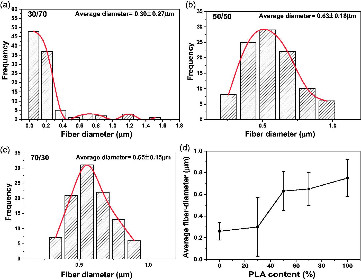
(a to c) Fiber diameter distribution profiles for PLA/PCL: 30/30, 50/50 and 70/30 ENMs respectively; (d) variation in average fiber diameter as a function of PLA content in PLA/PCL blended ENMs.

AFM images of (a) PLA, (b) PCL and (c) PLA/PCL (70:30 w/w) blended ENMs.
Variation in solution concentration of the blend
As discussed earlier, PLA/PCL (70/30 w/w) blend exhibited comparatively minimum bead defects and diameter variation. Thus, PLA rich composition was used to optimize the solution concentration of PLA/PCL blended fibers. The beaded morphologies were observed to decrease with the increase in solution concentration of PLA/PCL blend (∼8 wt. % to ∼12 wt. %) as evident from the SEM images shown in Figure 14. It was observed that bead defects and microdroplets appear in low solution concentration (≤8 wt. %) because of the inability of the electric force to maintain a continuous jet and thus tend to break into droplets before reaching the collector [26]. In addition, the disappearance of bead defects with the increase in solution concentration is attributed to the increase in solution viscosity which results in the formation of the straight jet along with the formation of Taylor cone at the needle tip. Thus, fiber diameter and diameter variation of the blend increased with the increase in solution concentration, with a minimum of ∼ 0.28 ± 0.07 µm for ∼ 8 wt. % solution to a maximum of ∼ 1.0 ± 0.2 µm for ∼ 12 wt. % solution as shown in Figure 15. However, a further elevation in electrospinning solution concentration (≥12 wt. %) results in an increase in fiber diameter and diameter variation because the elongation and stretching of the charged jet become difficult and slower. Thus, electrospinning becomes difficult for solutions with higher viscosities as the needle tip gets occluded after some time. As a result, ∼ 10 wt. % solution concentration was considered to be optimum for the fabrication of neat PLA, neat PCL and blended ENMs with minimum fiber diameter variation and bead defects.

SEM images of ENMs of PLA/PCL (70/30 w/w) blend for (a) ∼8 wt.% (b) ∼10 wt. % (c) ∼12 wt.% solution concentration.

Variation in average fiber diameter of PLA/PCL (70:30) blended ENMs with electrospinning solution concentration.
Variation in flow rate
The variation in average fiber diameter on increasing the PLA content amongst ENMs at flow rates ranging from ∼ 0.5 ml/h to ∼ 4 ml/h is shown in Figure 16 and summarized in Table 1. The average fiber diameter was observed to increase with the increase in PLA content as discussed earlier. The increase in flow rate resulted in an increase in both average fiber diameter and majorly diameter variations for all the compositions studied as shown in the fiber diameter variation curve in Figure 16. However, for neat PCL and PLA/PCL (30:70) based ENMs, average fiber diameter variation exhibited a significant increase with the increase in flow rate from ∼ 0.5 ml/h to ∼ 4 ml/h. This may be attributed to the increase in bead defects at higher flow rates due to the instability of continuous jet. Further, for PLA/PCL (50/50 w/w) blend, there was no significant variation in average fiber diameter. However, the diameter variation increased from ∼ 0.18 µm to ∼ 0.28 µm with an increase in flow rate from ∼ 0.5 ml/h to ∼ 4 ml/h. This may be attributed to the instability of jet resulting in the formation of bead defects amongst immiscible PLA and PCL phases for 1:1 blended ENMs. Moreover, the average fiber diameter and variations recorded for the flow rates, ∼ 0.5 ml/h and ∼ 1 ml/h, were observed to be comparable for most of the compositions studied. Thus, the flow rate of ∼ 1 ml/h was used for the fabrication of PLA and PCL based ENMs to increase the electrospun fiber deposition.
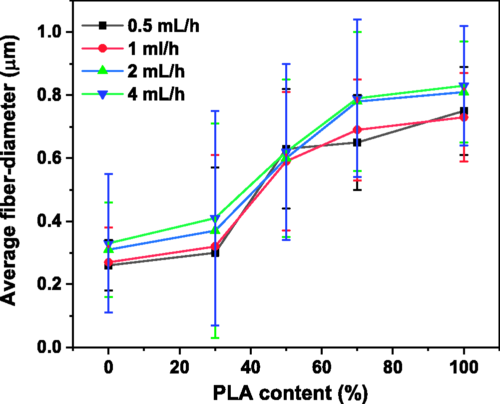
Variation of average fiber diameter as a function of PLA content amongst PLA/PCL blended ENMs at various flow rates.
Average fiber diameter and diameter variations (µm) at different flow rates for various PLA/PCL blended ENMs.

Physical performance evaluation (in-vitro)
The degree of swelling of PLA, PCL and PLA/PCL (70/30 w/w) blended ENMs were studied in acidic, neutral and basic media, using equation (1), for 48 h, as shown in Figure 17. In acidic (pH = 4) and neutral medium (pH = 7), the degree of swelling of PCL fibers was observed to be lower than PLA and PLA/PCL blended fibers. This may be attributed to a comparatively high crystallinity of PCL based ENMs than PLA [19,37]. However, in basic (pH = 9.2) and neutral medium (pH = 7), the degree of swelling of PLA/PCL blended fibers was observed to be higher than both PLA and PCL based fibers. The degree of swelling of ENMs has a direct correspondence with diffusion efficiency of release medium into the nanofibrous layers [38]. Thus, a significant diffusion of release medium was observed into inner layers of PLA/PCL (70/30 w/w) blended ENMs.

Variation in degree of swelling for PLA, PCL and PLA/PCL (70/30 w/w) blended ENMs in (a) acidic (pH = 4), (b) neutral (pH = 7) and (c) basic (pH = 9.2) release media.
The weight loss of PLA, PCL and PLA/PCL (70/30 w/w) ENMs was studied in acidic, neutral and basic media, using equation (2), for 48 h, as shown in Figure 18. The effective weight loss was observed to be less amongst PLA, PCL, and blended mats when observed for 48 h. Comparatively, minimum weight loss was observed for PCL and maximum for PLA based ENMs in all acidic, basic and neutral release media. This may be attributed to comparatively high crystallinity of PCL based ENMs and thus, a low diffusion of release media and weight loss was observed. Furthermore, a maximum weight loss was observed in the basic medium for all PLA, PCL and PLA/PCL (70:30) based ENMs after 48 hours as shown in Figure 18(d). Microscopic analysis of the surface morphologies of ENMs after 48 h is shown in Figure 19. An increase in bead defects was observed for PCL based ENMs in neutral and basic media after 48 h. A similar reappearance of beaded morphologies in PLA based ENMs was observed in neutral and basic media as shown in Figure 19. Increased average fiber diameter and variation were observed for PLA, PCL and PLA/PCL (70:30) blended ENMs in all the studied release media as shown in Figure 20. Moreover, an extraordinary increase in average fiber diameter was observed in neat PCL and neat PLA based ENMs in acidic media. However, the variation in the surface morphologies of blended ENMs was observed to occur to a lesser degree compared to neat PLA and PCL based ENMs and thus are potential candidates for the fabrication of biomedical devices, especially for drug delivery applications.

Variation in weight loss for PLA, PCL and PLA/PCL (70:30 w/w) blended ENMs in (a) acidic (pH = 4), (b) neutral (pH = 7) and (c) basic (pH = 9.2) release media, (d) variation in weight loss in acidic, basic and neutral media after 48 h.

SEM images of (a to c) PLA, (d to f) PCL and (g to i) PLA/PCL (70:30 w/w) after 48 h in acidic (pH = 4), neutral (pH = 7) and basic (pH = 9.2) media respectively.

Variation in average fiber diameter after 48 h in acidic (pH = 4), neutral (pH = 7) and basic (pH = 9.2) media.
Conclusion
Electrospinning process parameters optimization for the fabrication of electrospun nanofibrous mats (ENMs) based on PLA/PCL blend could be done to obtain mats with minimal diameter variation and bead defects. The optimal parameters for obtaining ENMs with appropriate fiber dimension with relatively bead free morphology while ensuring maximum fiber deposition have been found to be at an applied voltage of ∼ 20 kV, orifice diameter of ∼ 0.5 mm and a solvent mixture of CF/DMF in the ratio of 4:1 for the electrospinning of individual PLA and PCL based ENMs.
ENMs of PLA/PCL blends were prepared by implementing the optimal parameters ascertained for the neat components, i.e., PLA and PCL. The PLA/PCL blend composition is further optimized at a 70:30 (w/w) ratio and ∼ 10 wt. % electrospinning solution concentration resulted in the formation of ENMs with a combination of minimum bead defects and fiber diameter in the sub-micron scale. The flow rate of ∼ 1 ml/h was optimized for the fabrication of PLA/PCL blend based ENMs.
The degree of swelling of PCL based ENMs was observed to be lower than that of PLA and PLA/PCL blend based ENMs both in acidic (pH = 4) and neutral medium (pH = 7). Moreover, the degree of swelling of PLA/PCL blended fibers was observed to be higher than both PLA and PCL based neat fibers in both basic (pH = 9.2) and neutral medium (pH = 7). The investigations on weight-loss indicated a minimum for PCL and a maximum for PLA based ENMs irrespective of acidic, basic or neutral release mediums.
The study established a standard route for determining the set of optimal parameters for electrospinning assisted fabrication of PLA/PCL based blended ENMs and the physical performance evaluation of various PLA/PCL based ENMs sheds light on their potential applications in the fabrication of biomedical devices.
Footnotes
Acknowledgments
Lab facilities of CRF (Central Research facility) and NRF (Nanoscale Research Facility), IIT Delhi, are acknowledged.
Declaration of conflicting interests
The author(s) declared no potential conflicts of interest with respect to the research, authorship, and/or publication of this article.
Funding
The author(s) disclosed receipt of the following financial support for the research, authorship, and/or publication of this article: The authors acknowledge the research grant from ICMR (Indian Council of Medical Research; Ref: 5/3/8/320/2016-ITR) and financial support from MHRD (Ministry of Human Resource and Development), India.