
Abstract
Vacuum-Assisted Resin Infusion (VARI) and Resin Transfer Molding (RTM) techniques are the most common techniques for the manufacturing of polymeric composite laminates. The VARI technique has a lot of advantages such as low cost, free voids laminates and the ability to produce complex shapes. However, it has some drawbacks such as poor surface finish and temperature instabilities. On the contrary, the RTM technique can withstand high temperature, producing a good surface finish and complex shape laminates. However, it has a high tooling cost and poor quality laminates due to void contents. In this study, a new technique integrated both VARI and RTM techniques is developed to minimize their drawbacks. This technique involves using a semitransparent composite plate instead of a vacuum bag in the VARI technique. This semitransparent plate takes the inverse shape of the composite laminate similar to the RTM tooling. However, this plate has a low cost compared with RTM tooling and allows monitoring of the resin flow during the infusion process. To validate the integrated technique, the mechanical properties of composite laminates are compared with that produced by hand layup technique (HLT). Moreover, the influence of incorporation of 0.25 wt. % and 0.5 wt. % of titanium dioxide (TiO2) nanoparticle into woven and chopped fiber/epoxy composite laminates was demonstrated. The results indicated that the laminates fabricated by the integrated VARI method showed higher mechanical properties than those produced by the hand-layup technique. Moreover, glass fiber/epoxy filled with 0.25 wt. % of TiO2 nanoparticles gives high mechanical properties.
Keywords
Introduction
Recently, polymeric composite materials were used in structural applications ranging from aircraft and space structures to marine and automotive applications [1,2]. Vacuum resin infusion techniques are increasingly used in the manufacturing of these composites [3,4]. In the VARI technique, layers of fibrous material are presented on a rigid surface with net-shaped molding and under a bagging film. A vacuum pump is used to withdraw the air between the shaped molding surface and the bagging film compressing the fibrous material [5,6]. Consequently, air cavities can be minimized so that the produced composite part will have little free space thus producing composite products with good mechanical properties [7,8].
The advantage of the VARI technique is considering this technique as cost-effective to fabricate large-scale composites structures with the ability to produce complex parts in one operation [9]. Furthermore, composites with a higher fiber volume fractions can be manufactured using the VARI process which can be used in applications that need fibers to be the dominant material [10]. However, the drawbacks of the VARI process include thickness variation of the composite part due to non-uniform compaction pressure. Furthermore, poor surface finish is provided for composite laminates due to the wrinkling presented by the vacuum bag [11,12]. Moreover, heating the whole infusion setup to a high curing temperature is considered as a type of challenge because of using a vacuum bag [13]. Besides, the VARI technique includes difficulties in installing supplementary equipment, such as sealant tape, porous peel ply, vacuum bag, distribution media and breather [3]. Generally, these supplementary materials are not reusable after completing the process [5]. Consequently, a high amount of waste is produced.
On the other side, the Resin transfer molding (RTM) technique is commonly used in the manufacturing of polymeric matrix composites [14]. This technique mainly consists of two steps. The first step involves the mold-filling stage, which involves the injection of resin into the mold cavity containing the preform. In the second step, the mixture of resin and fiber is subjected to high temperatures that harden the catalyzed resin, and thus composite laminate is produced [15]. One major barrier to use the RTM technique is that the productivity of this technique is often lower than expected. This in turn will increase the cost of RTM components [16]. Moreover, the quality of composite laminates is influenced by the unbalanced flow of resin during the mold filling stage. Besides, the resin must have low viscosity and low shrinkage during the curing process.
There are a lot of researches attempted to minimize the problems of the VRI technique. Kazmi et al. [4] applied pressure variations in the stages of filling and post-filling to control both, the thickness and thus the fiber volume fractions of composite laminates manufactured with the VARI process. However, this may lead to increase the void content during the post-filling stage. Moreover, Yenilmez et al. [11] performed different compaction experiments to change the thickness of random fiber performs with an embedded polypropylene distribution medium. However, changing the thickness by pressure variation can be considered a waste of money. Ricciardi et al. [5], developed a modified innovative pulsed infusion technique for the manufacturing of fiber-reinforced thermoset composites. This technology involves using a double- vacuum bagging technique and a reusable pressure distributor. It can control the vacuum pressure in a pulsed way. Pulse infusion provides a cost-saving material advantage around 19% and a considerable waste reduction due to a minor consumption of polymer and the absence of the distribution network. Moreover, there is an increase in the flexural modulus and flexural strength by 9% and 24% respectively compared to the traditional vacuum infusion process. However, the main disadvantage of this technique is the preparation of the pressure distributor.
In recent years, epoxy nanocomposites have gained attractive attention because they give enhancement in mechanical properties compared to conventional composites [17,18]. Polymer nanocomposite can be used in the industry and in electrical applications such as insulating applications due to its dielectric characteristics [19,20]. Furthermore, nanoparticles can be added to polymer matrices to be used in biomedical applications [21]. Nano-filled composites have high flexural properties and impact resistance, so nanocomposites can be used for the aerospace industry [22]. Moreover, nanocomposites can be used for several sectors of industry like aerospace, automotive, electronics, and biotechnology [23]. Substantial improvements in mechanical, flammability and thermal properties have been achieved with nanocomposite laminates while maintaining similar density to those of the neat resin [24]. Furthermore, nanocomposites can be used in industrial applications owing to their high mechanical properties as tensile modulus, strength, flame resistance, barrier resistance, corrosion resistance, and stiffness [25,26].
Studies concerning the manufacturing of polymeric nanocomposites with VARI technique are limited as nanoparticles increase the viscosity of polymer solution thus hinders the easy flow of polymer into the fibrous material. Kumar and Sundaram [27] found that although the inclusion of Multi-walled carbon nanotube (MWCNT) to carbon/epoxy composites increased the viscosity and the mold filling time, it decreased the curing cycle duration to a substantial extent. Umer et al. [28] investigated the influence of adding graphene oxide (GO) nanoparticles on glass fiber/epoxy composite prepared using the resin infusion process. Different GO contents of 0.05, 0.1 and 0.2 wt. % were added. The results showed that adding GO to neat epoxy resin increased the viscosity and affected the resin cure reaction by reducing the resin gel time. Moreover, nanocomposites reinforced with 0.2 wt. % GO resulted in very slow polymer infiltration time with premature polymer gelation. Also, there is an increase of 21% and 30% in flexural modulus and flexural strength was attained by adding 0.2 wt. % GO to glass fiber/epoxy composite. Xia et al. [29] used CaCO3 nanoparticles to be impregnated to kenaf fibers through the VARI process. The results showed that the interfacial compatibility between fibers and resin matrix was significantly improved based on the comparison of the mechanical properties. Also, the modulus of elasticity, modulus of rupture, tensile modulus and tensile strength were improved by 33.1%, 64.3%, 22.3%, and 67.8%, respectively as compared to the non-treated kenaf fibers. Kaybal et al. [30] investigated the influence of 1, 2, 3, 4 and 5 wt.% nano-CaCO3 content on the tensile behavior of epoxy composites using the VARI process. It was found that the incorporation of 2 wt. % nano-CaCO3 significantly improved the tensile strength by 28%. Moghimi et al. [31] studied the incorporation of an epoxy matrix with hybrid MWCNT and nanosilica to fabricate woven carbon fabric/epoxy composites using VARI technique. It was found that nanocomposites containing a hybrid of MWCNT and nanosilica are better than the corresponding single nanoparticles with the same total weight content.
To overcome the drawbacks of both VARI and RTM techniques, an integrated technique between both vacuum assisted resin infusion and resin transfer molding techniques was developed. This technique is based on the use of a properly designed semitransparent composite laminate. This laminate takes the inverse shape of the composite product (similar to the RTM tooling). This semitransparent laminate supersedes the vacuum bag used in the VARI technique. This semitransparent plate takes the inverse shape of the composite laminate similar to the RTM tooling, however, this plate has a low cost compared with RTM tooling and allows monitoring the resin flow during the infusion process. This technique gives a uniform thickness to the polymeric composite product as compared with the traditional VARI technique [11,12]. Furthermore, there was no need for using for vacuum bag, peel ply, distribution media, and breather thus reduces the manufacturing cost as compared with other research [5,11,12]. Moreover, this technique allows controlling the part thickness without pressure variation as reported in [11]. Also, as compared with Fang et al. [13], the traditional VARI technique cannot withstand high temperature owing to the existence of the vacuum bag. The integrated technique can withstand high temperatures as a semitransparent composite laminate was replaced. Besides, low tooling cost was achieved as compared with the tooling used in the RTM technique [16]. The quality of this technique was checked by comparing the mechanical properties of neat woven/chopped glass fiber/epoxy composites manufactured by this technique and equivalent ones manufactured by the hand-layup technique. Moreover, this technique was used for the manufacturing of nanofilled glass fiber reinforced epoxy composite. Metallic oxide fillers were generally used to strengthen epoxy composites so enhance their mechanical and physical properties [32]. Rigid, inorganic nanoparticles as TiO2 enhance the toughness of the epoxy matrices without affecting its glass transition temperature. Titanium dioxide nanoparticles can be added to produce electrical insulators [20] and smart composite materials [33]. Adding the optimum amount of TiO2 nanoparticles improves the flexural strength and modulus significantly [34]. Besides, TiO2 nanoparticles were used in this study owing to their easy availability and low cost. The effect of different weight fractions of titanium dioxide (TiO2) nanoparticles on tensile, flexural and hardness behavior of woven/chopped glass fiber/epoxy composites was investigated.
Experimental work
Materials
The composite laminates were fabricated using an epoxy system, Kemapoxy 150 RGL, as the polymeric matrix. Two types of commercially E-glass fiber reinforcements are used as primary reinforcements, i.e. woven and chopped E-glass fibers. The secondary reinforcement used for the composites was Titanium dioxide nanopowder with a diameter of 18 nm. This nanopowder was supplied by US Research Nanomaterials, Inc.
The semitransparent composite plate that supersedes the vacuum bag was manufactured from commercially woven glass fiber mats and an epoxy system Kemapoxy 150 RGL with 12 layers of woven E-glass fiber with a density of 200 g/m2. The specifications of woven and chopped E-glass fiber mats are shown in Table 1 given by the supplier.
Properties of glass fiber [35].

Methods
Preparation of the upper mold (semitransparent composite laminate)
In this study, hand lay-up technique (HLT) is used to fabricate the semitransparent composite laminate that takes the inverse shape of any required product. This laminate was prepared from epoxy reinforced with 12 layers of woven E-glass fiber with a density of 200 g/m2. A metallic roller was used to extract the excess resin and also to reduce air voids in the polymeric composite laminate. The mold was kept at room temperature for about 24 hr after de-molding. The laminate was cured in a furnace for 4 hr at 80 °C. This semitransparent composite plate has dimensions of 500 x 450 x 5 mm3. After, the composite plate was post-cured for 48 hr, four rectangular edges of width 40 mm. These edges were performed by 12 layers of woven E-glass fiber impregnated with epoxy resin via hand lay-up process. The thickness of these edges was used to control the thickness of the manufactured laminate. After the composite plate and edges were completely cured, two holes of diameter 12 mm were drilled as shown in Figure 1(a).

The semitransparent composite plate with (a) two holes and 4 edges, (b) with the two syringes, (c) with the inlet and outlet hoses, (d) A schematic diagram of the new combined technique assembly.
Fabrication of neat and nano-filled composite laminates via the integrated technique
Like the conventional vacuum infusion technique, this combined technique consists of three main stages: pre-infusion, infusion, and post-infusion [13]. In the pre-infusion stage, we are applying wax all over the surface of the mold and the semitransparent plate, then the mold and composite plate were left to dry. Two open syringes are inserted into the two holes of the plate as shown in Figure 1(b). Two hoses of internal diameters of 12 mm are fitted to the two syringes one represents the inlet and the other represents the outlet. To ensure the uniform dispersion of the resin into the mold, a suitable distance between the inlet syringe and the layers of glass fiber was performed. To allow the transfer of resin from the syringe, this distance was attained in the inlet syringe by cutting a part from its end as shown in Figure 1(c). This distance helps in the uniformity of the resin flow before fiber impregnation. Moreover, the spacing between fiber layers is sufficient enough for the uniform flow of resin filled with small size TiO2 nanoparticles as shown in Figure 2(a) and (b).This figure shows the uniform flow of epoxy during the initial filling stage and the final filling stage, respectively.

The uniform flow of epoxy during the (a) initial filling stage and (b) the final filling stage.
The inlet hose is connected to the resin inlet and the outlet hose is connected to the resin trap. The sealant tape is then applied to the edges of the composite plate to adhere the plate to the mold. The preform is laid on the surface of the mold and beneath the composite plate to produce required laminate. The woven glass fiber/epoxy laminates was prepared from epoxy reinforced with 12 layers of woven E-glass fiber with a density of 200 g/m2. The chopped glass fiber/epoxy laminates was prepared from epoxy reinforced with 8 layers of chopped E-glass fiber with a density of 300 g/m2. The fiber volume fraction of either woven or chopped E-glass fibers is 32%. The volume fraction of woven or chopped E-glass fibers was determined experimentally by evaporating of polymeric matrix using the ignition technique according to ASTM D3171-99 [36–40]. A vacuum pump is connected to the resin trap similar to the traditional VARI process shown in Figure 1(d). The infusion and post-infusion stages are similar to the traditional VARI process. The vacuum pressure used to suck epoxy resin is 27 inHg in the manufacturing of all laminates. A chance of sedimentation of nano-particles may occur when the epoxy and TiO2 nanoparticles mixture is sucked by the vacuum pump. To overcome this sedimentation, the dispersion uniformity was assured due to five reasons: the first reason is the small thickness (3 mm) of the composite laminate that does not help in sedimentation (probability of sedimentation increases with the increase of thickness). The second reason is the existence of at least 8 layers of fiber (and hence 9 regions for stream) that divide the whole thickness (3/9 = 0.333 mm) and increase the possibility of dispersion. The third is the speed of the mixture (due to a strong vacuum pump) during the suction process, which does not give the chance for sedimentation. The fourth is the high viscosity of epoxy which prevents any kind of sedimentation (the high viscosity of epoxy reduces the possibility of sedimentation). The fifth is the small weight percent of nanoparticle used (0.25 wt. % (1.1 gram) and 0.5 wt. % (2.2 gram)). Due to the small size of nano-fillers and the absence of any larger aggregates, the nano-fillers can easily penetrate all fiber structures without compromising the impregnation by excessive viscosity, thereby enabling all the state-of-the-art process (integrated technique). Also, as the size of nanoparticles decreases, it becomes more difficult for sedimentation to occur.
Nanocomposites fabrication
Titanium dioxide nanoparticles were dispersed in epoxy resin via the sonication process. Mixing was stirred manually for 5 min then conducted with Hielscher ultrasonic processor UP 200 S (200 W, frequency 24 kHz). Sonication was performed with a pulse ratio of 0.5 s on/0.5s off with amplitude of 55% for 1 hr. In order to avoid resin degradation, the epoxy and TiO2 nanoparticles mixture was cooled by placing a bath of ice water during the sonication process [41]. Subsequently, a hardener was manually added to the mixture of epoxy and TiO2 nanoparticles with a ratio of 1:2 by weight of the epoxy resin. The mixture was then placed in a resin reservoir then infused into the mold by a vacuum pump. Epoxy and TiO2 nanoparticles mixture were sucked from the inlet and distributed to impregnate the layers of glass fibers mats whether woven or chopped glass fibers.
The incorporation of TiO2 nanoparticles to epoxy resin increases the viscosity as shown in Table 2. Further increase in TiO2 nanoparticles content leads to an increase in the viscosity thus the mold filling time increases. The viscosity values of unfilled epoxy, epoxy filled with 0.25 wt. % TiO2 nanoparticles and epoxy filled with 0.5 wt. % TiO2 nanoparticles were measured by using a falling body viscometer. One of the major obstacles when adding nanoparticles to epoxy resins is the increase in viscosity. The extent of altered flow behavior depends on many variables like particle size, shape and fluid/particle interaction [42]. The stronger the interface between the epoxy resin and nanoparticle surface, the higher the resin viscosity. The impregnated preform remained under vacuum till hardening occurred. The laminates were cured in a furnace for 4 hr at 80 °C. A schematic diagram of the preparation procedures of TiO2 nanoparticles reinforced GFRE composites is shown in Figure 3.
The viscosity of neat and nanofilled epoxy.

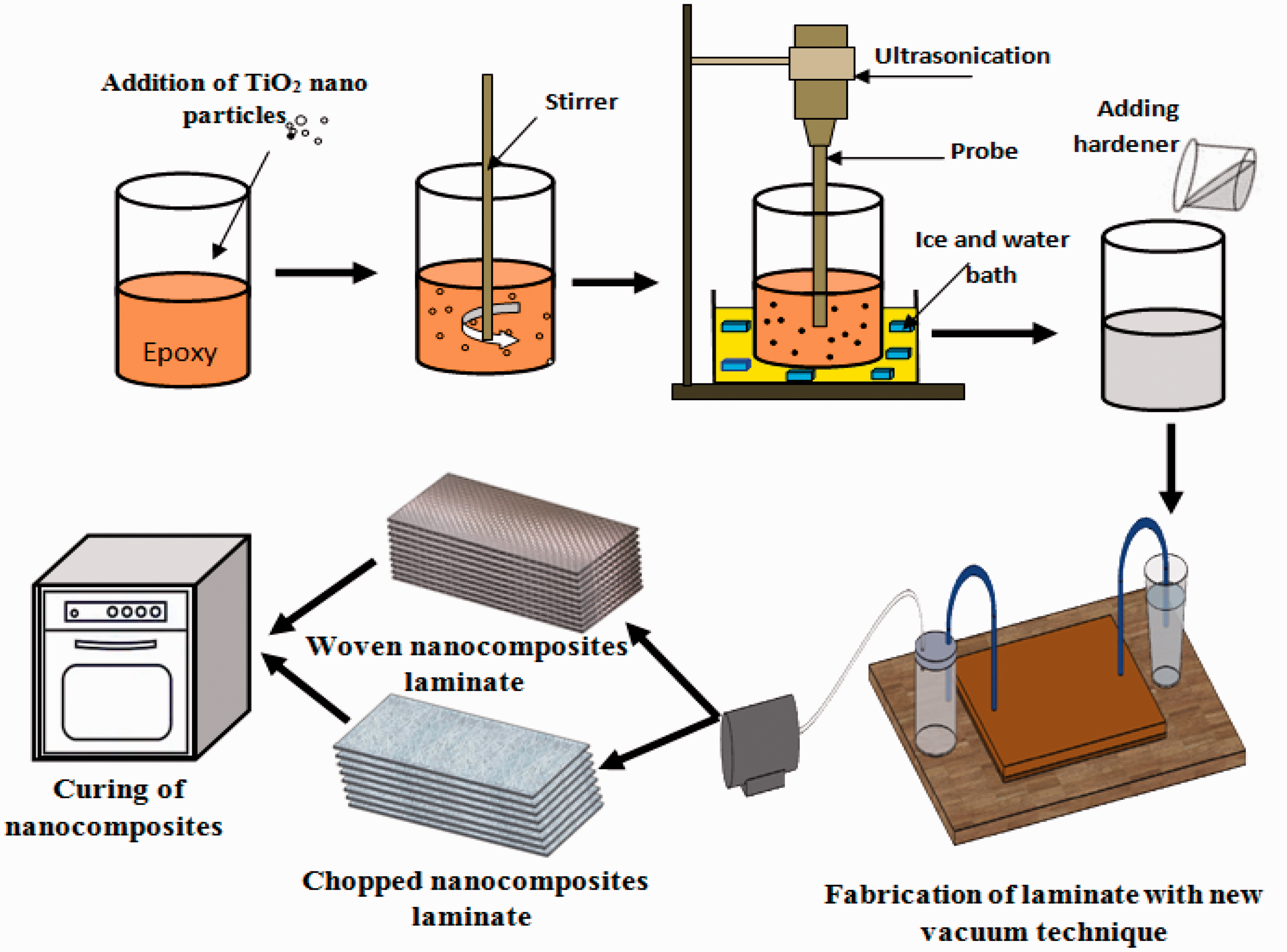
Schematic diagram for the fabrication sequences of TiO2 nanocomposites using integrated technique.
Mechanical characterization
Tensile test
The tensile properties of the fabricated composite laminate were measured according to ASTM D3039/D3039M [43]. The polymeric composite samples were cut into strips with a length of 250 mm, a width of 25 mm, and a thickness of 3 mm. The ultimate tensile strength, toughness, the apparent Young’s modulus, and strain were estimated using the curve of stress-strain obtained from the tension test as follows


Three-point flexural test
The flexural test was performed by using three-point flexural test and was conducted by using Jinan Test Machine WDW 100 KN universal testing machine according to ASTM standard D-790-10 [44]. The composites flexural strength was calculated according to the following equation:
Where F is the applied flexural load (N), L is the support span length (mm). The flexural strain is determined from the following equation:
Where D is the maximum deflection of the composite specimen center and t is considered as the specimen thickness. The deflection of mid-span of the specimens was calculated from the movement of the loading nose relative to the supports of the specimen. This deflection was used to calculate the flexural modulus. The modulus of elasticity in bending can be calculated from the equation: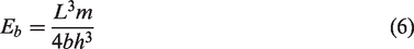
Where L is the support span length; m is the slope of the tangent to the straight-line portion of the load-deflection curve. Five specimens had been tested for each sample where the average value was calculated to represent the obtained value from the flexural test.
Hardness
Barcol hardness testing is a method of measuring the hardness of reinforced and non-reinforced rigid plastics. The hardness was measured at eight different locations of the fabricated composite specimens and the average value was calculated. Hardness was measured using the PCE-1000N Hardness Tester apparatus. Each sample was labeled by name, number, and indentation locations. The indentation locations were referenced along a line drawn from left to the right end of the tested specimen. The first indentation location was taken along the longitudinal axis at 4 mm toward the center of the specimen. Subsequent points were followed by 4 mm intervals from the first point toward the right end.
Microstructure examination
Scanning electron microscopy (SEM) was conducted to observe the morphology of the fracture surfaces of the manufactured composites using a FEI Quanta 250 FEG instrument. Fracture surfaces of the polymer composites were sputter-coated with gold before each analysis to improve resolution.
Density and void content of the fabricated composites
Air or other volatiles may exist in the composite laminate during fabrication process. The most common reason for void formation is the incapability of the epoxy matrix to displace entrained air in fibers during impregnation stage [45]. The void content of the fabricated composite laminate was determined according to ASTM D2734-09 [46] standard using the following equations:
The theoretical and experimental density of the manufactured composites was determined using the rule of hybrid mixture according to ASTM D792-00 [47] using the following equations [35,39,40,48,49]:
And
where ρexperimental is the actual density measured experimentally on manufactured composite specimens, Vm, VGF, Vp are the volume fraction of epoxy matrix, glass fiber, nano or micron particle respectively and ρm, ρGF, ρp are the density of epoxy matrix, glass fiber, nano or micron particle respectively.
Results and discussions
Tensile test
The comparison between tensile properties of neat and nanofilled woven and chopped GFRE produced by the new integrated technique is discussed below. Table 3 shows the types of fabricated composite laminates. Figure 4 shows the tensile stress-strain curve for neat and nanofilled woven GFRE specimens manufactured by integrated technique and neat woven GFRE manufactured by hand layup technique. This figure shows that the neat woven produced by the integrated technique exhibits higher tensile properties compared with that produced by hand layup technique. Moreover, woven GFRE filled with 0.25 wt. % TiO2 nanoparticles (VWN0.25) exhibit higher tensile stress and strain over neat woven GFRE. However, a further increase of TiO2 nanoparticles content to 0.5 wt.% into woven GFRE (VWN0.5) decreases the tensile stress as compared to VWN0.25 but still higher than that of neat GFRE.
The types of fabricated composite laminates.


Tensile stress-strain curve for Hand layup woven GFRE laminate, Vacuum neat woven GFRE, Vacuum nanofilled (0.25 wt. %) woven GFRE, and Vacuum nanofilled (0. 5 wt. %) woven GFRE.
Figure 5 shows the tensile stress-strain curve for neat chopped GFRE manufactured by hand layup technique, neat and nano-filled chopped GFRE specimens manufactured by integrated technique. It is clear from this figure that the neat chopped produced by the integrated technique exhibits higher tensile properties compared with that produced by hand layup technique. Chopped GFRE filled with 0.25 wt. % TiO2 nanoparticles (VCN0.25) exhibits higher tensile stress over neat chopped GFRE. However, a further increase of TiO2 nanoparticles content to 0.5 wt% into chopped GFRE (VCN0.5) leads to deterioration of the tensile stress as compared to neat chopped GFRE.

Tensile stress-strain curve for Hand layup chopped GFRE laminate, Vacuum neat chopped GFRE, Vacuum nanofilled (0.25 wt. %) chopped GFRE, and Vacuum nanofilled (0.5 wt. %) chopped GFRE.
Figure 6 shows the tensile properties of neat and nanofilled woven and chopped GFRE include ultimate tensile strength, strain to failure, tensile modulus, and toughness. The toughness is the ability of the material to absorb energy without fracture. Toughness was obtained from the area under the stress-strain curve [32]. The reason for the difference between values of the bar chart and stress-strain curve that the stress strain-curve was drawn for three test specimens, while the bar chart value represented the average value calculated for all tested specimens. It is clear from the figure that all the tensile properties of both neat woven and chopped composite laminates fabricated by the integrated vacuum technique is higher than that fabricated with hand lay-up technique. Significant enhancement of 40.04%, 10.09%, 15.91% and 42.42% in tensile strength, strain to failure, Young’s modulus and toughness, respectively, was obtained in chopped GFRE laminate manufactured by the integrated vacuum technique compared with HLT. However, an enhancement of 35.7%, 21.9%, 1.3% and 61% in tensile strength, strain to failure, tensile modulus, and toughness, respectively, is observed with woven composite laminates manufactured by integrated vacuum technique as compared to HLT. Yaacob et al. [50] made a comparison according to mechanical properties between laminates prepared by traditional VARI technique and hand layup technique. It was found that the enhancement in the tensile strength of laminates manufactured using VARI technique was 27%. Yuhazri et al. [51] compared between traditional VARI technique and hand layup technique toward kenaf/polyester composites. Enhancements in tensile strength and modulus by 27.5%, and 2.85%, respectively were found in comparison with hand layup technique. Abdurohman et al. [52] compare between hand layup, vacuum infusion and vacuum bagging methods toward E-glass. It was found that there was an improvement in the tensile strength and strain by 32.6%, and 7.85%, respectively compared with hand layup technique. However, vacuum bagging improves the tensile strength and strain by 3.9% and 5%, respectively compared with hand layup technique. Roopa et al. [53] investigated the mechanical properties of glass fiber/polyester composites fabricated by hand layup and Resin Transfer Molding techniques. It was found that the tensile strength for RTM laminates were 21% greater than those produced by hand layup technique. Cavatorta [54] investigated the effect of RTM and hand layup technique on the fatigue and mechanical properties of carbon-glass/epoxy laminates. It was found RTM specimens have higher tensile strength and modulus by 11.5% and 4.8% compared with hand layup specimens. From the previous results, it is clear that the integrated technique is better than traditional VARI and RTM technique as compared to hand lay-up technique according to the tensile properties of composite laminates.

Tensile properties of HLT, neat and nanofilled woven and chopped GFRE, (a) Ultimate tensile strength, (b) strain to failure, (c) tensile modulus, (d) toughness.
Raajeshkrishna and Chandramohan [55] used woven glass fabrics as reinforcement and thermosetting epoxy matrix to produce composite laminates by using VARI technique. It was found that the tensile strength of the resulted laminates was 170 MPa. The integrated technique showed a higher tensile strength (212 MPa) with an enhancement of 24.7%. Moreover, the tensile strain of glass fiber reinforced polymer composites manufactured by VARI technique is 2.36 as reported in [56]. The tensile strain of VNW obtained with the integrated technique was 5.12, so the improvement in the tensile strain obtained with the integrated technique was 116.7%. Furthermore, the tensile strength for chopped GFRE laminates manufactured by VARI technique was 135 MPa [57]. The tensile strength of chopped E-glass/epoxy composites produced by the integrated technique was 167.14 MPa, so the enhancement compared with traditional VARI was 23.8%. Anas et al. [58] utilized RTM technique to produce chopped GFRE and the tensile strength was 102.6 MPa, however, the tensile strength of chopped E-glass manufactured by the integrated technique was 167.14. An enhancement in the tensile strength of VNC produced by the integrated technique was 62.9% as compared with traditional RTM. Moreover, Borodulin et al. [59] produced chopped GFRE laminates by RTM technique with tensile strength of 109 MPa. The enhancement in the tensile strength An enhancement in the tensile strength of VNC fabricated by the integrated technique was 53.3% as compared with traditional RTM. The tensile strength and modulus for chopped GFRE laminates produced by RTM technique were 76.4 MPa and 3 GPa respectively [60]. The enhancement in the tensile strength and modulus compared with traditional RTM were 118.8% and 0.02% respectively. Kunrath et al. [61] used RTM technique to manufacture neat and nanofilled weave GFRE laminates. The tensile strength of neat weave GFRE laminates was 128.9 MPa. The enhancement in tensile strength of VNW produced by the integrated technique was 64.5%.
Enhancements of 31.1%, 5.47%, 10.2% and 35.7% in tensile strength, strain to failure, Young’s modulus, and toughness were obtained in woven GFRE filled with 0.25 wt% TiO2 nanoparticles, respectively, as compared to neat woven GFRE. Moreover, significant enhancements of 1.76%, 1.85%, 10% and 4.4% in tensile strength, strain to failure, Young’s modulus and toughness are obtained in chopped GFRE filled with 0.25 wt.% TiO2 nanoparticles, respectively, as compared to neat chopped GFRE. However, on further increasing the content of TiO2 nanoparticles, the trend reverses. It is inferred that enhancement in mechanical properties requires an optimal inclusion of nanoparticles as at higher addition of nanoparticles; chances of formation of agglomerates are dominant [62]. Moreover, Titanium dioxide nanoparticles can give higher mechanical properties compared with other nanoparticles. Kumar and Sundaram [27] found that although the inclusion of MWCNT gives a slight increase in the mechanical properties of nanocomposite laminates compared with the neat composites. Furthermore, using the optimum percentages of graphene nanoparticles led to 22% increase in the composite tensile strength [26]. Besides, an increase of 23.6% and 34.1% in the tensile and flexural strength was achieved by adding the optimum amount of nanoclay to glass fiber reinforced epoxy [63]. Also, Kaybal et al. [30] reported that nano-CaCO3 improved the tensile strength of epoxy composites by 28%.
The deterioration in the tensile properties in VWN0.5 and VCN0.5 was occurred due to the agglomeration attained with the incorporation of more and more nanoparticles. These agglomerations give a higher surface area that helps in the formation of enclosed air bubbles from the atmosphere. The aggregation of TiO2 nanoparticles reduces the potential improvement of mechanical properties owing to the restriction of the interfacial area [64]. When the nanocomposites are subjected to force, the TiO2 nanoparticle agglomerates are split easily thus a premature failure of the polymeric composite materials takes place [65].
Figures 7 and 8 shows the tensile fracture surface of woven and chopped glass fiber reinforced epoxy respectively. These figures indicate that matrix cracking, fiber breakage and delamination between composite layers are the main types of failure. Figures 7(a) and 8(a) show the tensile fracture surface of HW and HC, respectively. Nevertheless, Figures 7(b) and 8(b) show the tensile fracture surface of VNW and VNC. It can be observed that in neat GFRE composites fabricated with Hand lay-up and integrated technique, the damaged area was propagated to greater regions. The bad adhesion of glass fiber reinforced epoxy matrix in the composite layers in neat GFRE, fiber pullout and matrix cracking led to bad stress transmission between the epoxy and glass fiber resulting in a relatively low tensile strength. However, incorporation of nanoparticles enhances the bonding between matrix and glass fibers especially for small content of 0.25 wt. % TiO2 nanoparticles. Adding 0.25 wt. % TiO2 nanoparticles to WNV and VNC suppressed the propagation of damage in nano-filled laminates and simultaneously promoted the transfer of the load to the primary reinforcements as shown in Figure 7(c) and Figure 8(c), respectively. The permanent damage generated in glass fiber/epoxy filled with TiO2 nanoparticles laminates was observed to be less than the neat GFRE composites which revealed the effect of TiO2 nanoparticles in reducing the damage propagation. Nanoparticles play an essential role in reducing the initial failure of the matrix by enhancing the fracture toughness of the epoxy matrix system, thus preserving the structural integrity of the composite laminate. Consequently, the inclusion of TiO2 nanoparticles into epoxy matrix increases the strength of the nano-filled polymeric composite. The good bonding between the nanocomposite laminate layers increases the adhesion between the epoxy matrix and glass fibers. The dominant failure occurred due to fiber breakage without producing delamination between nanocomposite layers. Slight delamination was observed for nano-filled laminates reinforced 0.25 wt.% TiO2 nanoparticles indicating good interfacial bond leading to a decrease of the crack energy dissipation. However, adding 0.5 wt. % TiO2 nanoparticles to WNV and VNC shows delamination in the fracture region as shown in Figure 7(d) and Figure 8(d), respectively. This delamination, as well as fiber breakage, decreased the tensile strength as compared with GFRE filled with 0.5 wt. % TiO2 nanoparticles. Increasing the content of TiO2 nanoparticles may cause agglomeration which in turn weakens the glass fiber/epoxy matrix interfacial zone and permits for an easy path for the cracks to propagate.

The fractured of woven glass fiber/epoxy tensile specimens, (a) HW, (b) VNW, (c)VWN0.25, and VWN0.5.
The fractured of chopped glass fiber/epoxy tensile specimens (a) HC, (b) VNC, (c)VCN0.25, and VCN0.5.
Flexural behavior
The flexural properties of neat and nanofilled woven and chopped GFRE fabricated by the new technique are discussed below. Figure 9(a) shows the flexural stress-strain curve for three different woven specimens manufactured by hand layup technique. Figure 9(b) to (d) shows the flexural stress-strain curve for three different woven specimens of neat, VWN0.25 and VWN0.5, respectively. However, Figure 10(a) shows the flexural stress-strain curve for three different chopped specimens manufactured by hand layup technique. Figure 10(b) to (d) shows the flexural stress-strain curve for three different chopped specimens of neat, VCN0.25 and VCN0.5, respectively.

Flexural stress-strain curve for three different specimens (a) Hand layup chopped GFRE laminate, (b) Vacuum neat chopped GFRE, (c) Vacuum nanofilled (0.25 wt.%) chopped GFRE and (d) Vacuum nanofilled (0. 5 wt.%) chopped GFRE.

Flexural stress-strain curve for three different specimens (a) Hand layup chopped GFRE laminate, (b) Vacuum neat chopped GFRE, (c) Vacuum nanofilled (0.25 wt.%) chopped GFRE and (d) Vacuum nanofilled (0. 5 wt.%) chopped GFRE.
Figure 11(a) to (c) shows the flexural properties of HLT, neat and nanofilled woven and chopped GFRE flexural strength, flexural strain, and flexural modulus. This figure shows that woven GFRE filled with 0.25 wt. % TiO2 nanoparticles (VWN0.25) exhibit higher flexural stress and strain over neat woven GFRE. However, a further increase of TiO2 nanoparticles content to 0.5 wt% into woven GFRE (VWN0.5) decreases the flexural stress as compared to VWN0.25 but still higher than of neat GFRE. Moreover, Figure 11(a) chopped GFRE filled with 0.5 wt% TiO2 nanoparticles (VCN0.5) exhibits higher flexural stress over neat chopped GFRE. It is obvious from this Figure that all the flexural properties of both neat woven and chopped composite laminates fabricated by integrated vacuum technique are higher than that fabricated with HLT. Significant enhancement of 45.73%, 17.4%, and 35.6% in flexural strength, flexural strain, and flexural modulus, respectively, was obtained in woven GFRE laminate manufactured by the new technique compared with HLT. Significant enhancements of 116.45%, 17.73%, and 105% in flexural strength, flexural strain, and flexural modulus, respectively, were obtained in chopped GFRE laminate manufactured by the integrated vacuum technique compared with HLT. From these results, a good enhancement of the flexural properties of chopped composite laminates is attained by the integrated vacuum technique over that fabricated by HLT. However, adequate enhancement of the flexural properties of woven composite laminates is attained by the integrated vacuum technique over that fabricated by HLT. Yaacob et al. [50] reported that the flexural strength of glass fiber composite laminates manufactured by VARI technique is higher than that produced by HLT by 34%. Atas et al. [66] found that the flexural strength of the composite specimens formed by VARI process is higher than that of hand lay-up by 54%. Rydarowski and Koziol [67] reported that the flexural strength of polymer reinforced by plain woven fabric and chopped strand mat produced by the HLT were 64 MPa and 35 MPa, respectively. However, the flexural strength of polymer reinforced by plain woven fabric and chopped strand mat by the VRI method were 30 MPa and 20 MPa, respectively. Davallo and Pasdar [68] compared between the flexural Properties of glass fiber/polyester composite laminates produced by RTM and those produced by hand lay-up technique. It was found that the flexural strength and modulus of the continuous and random glass-polyester composite laminates manufactured by HLT were 110 MPa and 10 GPa, respectively. While the flexural strength and modulus of the composite laminates manufactured by RTM technique were 120 MPa and 11 GPa, respectively. These results indicate that the enhancements in flexural strength and modulus are 9.1% and 10%, respectively. Cavatorta [54] reported that composite specimens produced by RTM have higher flexural strength and modulus by 3.4% and 10.1% compared with hand layup specimens. Pishvar et al. [69] compared the flexural properties of composites produced by wet lay-up/vacuum bagging and that produced by vacuum assisted resin transfer molding. It was found that the flexural strength and flexural modulus enhanced by 28% and 67%, respectively. From these results, it is clear that the integrated technique is better than traditional VRI and RTM technique according to the flexural properties of composite laminates.

Flexural properties of HLT, neat and nanofilled woven and chopped GFRE (a) Flexural strength, (b) flexural strain, (c) flexural modulus.
Umer et al. [28] used VARI technique to produce neat and nanofilled epoxy/glass fiber composite laminates. The flexural strength and modulus of neat specimens have the values of 265 MPa and 11 GPa, respectively. The enhancement in flexural strength and modulus of GFRE fabricated with integrated techniques are 276.23 MPa and 13.015 GPa, respectively. The increase in the flexural strength and modulus were 4.2% and 18.3%, respectively, [70]. Moreover, woven E-glass/Epoxy composite laminates was fabricated by VARI technique with a flexural strength of 250 MPa at 40% fiber volume fraction. However, the integrated technique showed an enhancement in the flexural strength by 10.5% with lower fiber volume fraction of 32%. Chen et al. [71] reported that the flexural strength of chopped E-glass manufactured by VARI technique was 65 MPa, whilst the flexural strength of VNC produced with the integrated technique was 115.6 MPa. The enhancement in the flexural strength of VNC produced with the integrated technique was 77.8% compared with chopped laminates manufactured by VARI technique. Also, the flexural strength for plain weave glass fabric composites produced by VARI technique was 260 MPa [67]. So, the enhancement of VNW produced with the integrated technique was 6.2% as compared to VARI technique. Kunrath et al. [61] used RTM technique to manufacture neat and nanofilled weave GFRE laminates. The flexural strength and modulus of neat weave GFRE laminates were 192.5 MPa and 10.9 GPa, respectively. The enhancement in the flexural strength and modulus of VNW fabricated with the integrated technique were 43.5% and 19.4%, respectively.
A significant enhancement of 105.3%, 23.8%, and 53.6% in flexural strength, flexural strain and flexural modulus in chopped GFRE filled with 0.5 wt. % TiO2 nanoparticles, respectively, as compared to neat chopped GFRE. However, a significant enhancement of 16.8%, 3.4% and 37.7% in flexural strength, flexural strain, and flexural modulus are obtained in woven GFRE filled with 0.25 wt. % TiO2 nanoparticles, respectively, as compared to neat woven GFRE.
A decrease in flexural strength in woven GFRE was obtained with further incorporation of TiO2 nanoparticles. This may be attributed to the strong attractive interaction between further TiO2 nanoparticles results in the formation of agglomeration. The loosely joint nanoparticles can show the agglomeration. It is essential in the fabrication of nanocomposites to overcome the attractive forces performed between the TiO2 nanoparticles producing these agglomerations [72]. Aggregation of TiO2 nanoparticles and voids located in the polymeric matrix composites clearly deteriorate the flexural properties as compared to woven GFRE filled with 0.25 wt% TiO2 nanoparticles due to the restriction of the interfacial area [73]. However, a further increase in TiO2 nanoparticles leads to improvement in flexural strength in chopped GFRE. This may be attributed to the rapid flow of nanophase epoxy during fabrication, which was occurred with chopped glass fiber thus the impregnation in the outer layers was better than the inner layers. This leads to good adhesion between the TiO2 nanoparticles with the chopped glass fiber in the outer layers thus stiffer exterior layers was performed than the inner layers of VCN0.5 specimen. This reveals the reason for increasing flexural strength and decreasing tensile strength in VCN0.5 specimen with increasing the TiO2 nanoparticles content. Titanium dioxide nanoparticles can improve the flexural properties of nanocomposite laminates as compared with other nanoparticles. Umer et al. [28] reported that specimens filled with 0.2 wt.% graphene oxide nanofillers gives very slow resin infiltration time. Also, an increase of 30% and 21% in the flexural strength and flexural modulus are demonstrated by adding graphene oxide nanoparticles as the secondary reinforcement to glass fiber composite laminates.
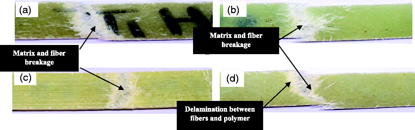
Figures 12 and 13 show the compressed side of fractured woven glass fiber/epoxy specimens after flexural test. It is clear that delamination between glass fiber and epoxy is the main sign of failure. Figure 12(a) and 13(a) shows the flexural fracture surface of HW and HC, respectively. However, Figure 12(b) and 13(b) shows the flexural fracture surface of VNW and VNC, respectively. It can be depicted that the delamination area in neat GFRE composites fabricated with Hand lay-up is greater than that of neat GFRE produced by integrated technique. Delamination was occurred during flexural testing was centered in the middle plane. As shown in Figures 12(c) and 13(c), inclusion of 0.25 wt. % TiO2 nanoparticles to epoxy leads to better resistance in GFRE against flexural loading. Epoxy filled with TiO2 nanoparticles offered more efficient stress transfer which decreased the local stress concentration around the interlayer of glass fiber and epoxy matrix. This enhances the interfacial adhesion of nanocomposites and hence the flexural strength increased. Delamination and matrix debonding could be observed in VNW filled with 0.5 wt. % TiO2 nanoparticles as shown in Figure 12(d). This delamination revealed weak bonding between woven glass fibers and nanophase epoxy results in deterioration in the flexural strength as compared to VWN0.25. However, a slight delamination was observed in VNC filled with 0.5 wt. % TiO2 nanoparticles as shown in Figure 13(d).
The fractured woven glass fiber/epoxy specimens after flexural test (a) HW, (b) VNW, (c) VWN0.25, and (d) VWN0.5.

The fractured chopped glass fiber/epoxy specimens after flexural test (a) HC, (b) VNC, (c) VCN0.25, and (d) VCN0.5.
Figure 14 shows the SEM of neat woven GFRE. Moreover, Figure 15 indicates the SEM of woven GFRE filled with 0.25 wt. % TiO2 nanoparticles. From Figure, a relatively good dispersion of TiO2 nanoparticles was observed. This good dispersion of TiO2 nanoparticles in woven GFRE revealed the good tensile and flexural properties over the neat GFRE. Improving the mechanical properties depends on the good dispersion of nanoparticles inside the polymeric matrix [74,75]. Dispersing of TiO2 nanoparticles into epoxy homogenously permits for gaining the full benefit of the high interfacial area of the TiO2 nanoparticles and epoxy matrix. Figure 16 shows the SEM of woven GFRE filled with 0.5 wt. % TiO2 nanoparticles. This Figure clearly shows an agglomeration of TiO2 nanoparticles occurs in epoxy reinforced woven glass fiber. This agglomeration causes defects in the composite laminates and acts as stress concentration thus generates cracks that result in early failure. These improvements in mechanical properties of 0.25 wt. % TiO2 are due to good dispersion and distribution of nanoparticles compared with 0.5 wt. % nanoparticles.

SEM of neat woven Glass fiber/epoxy composites.
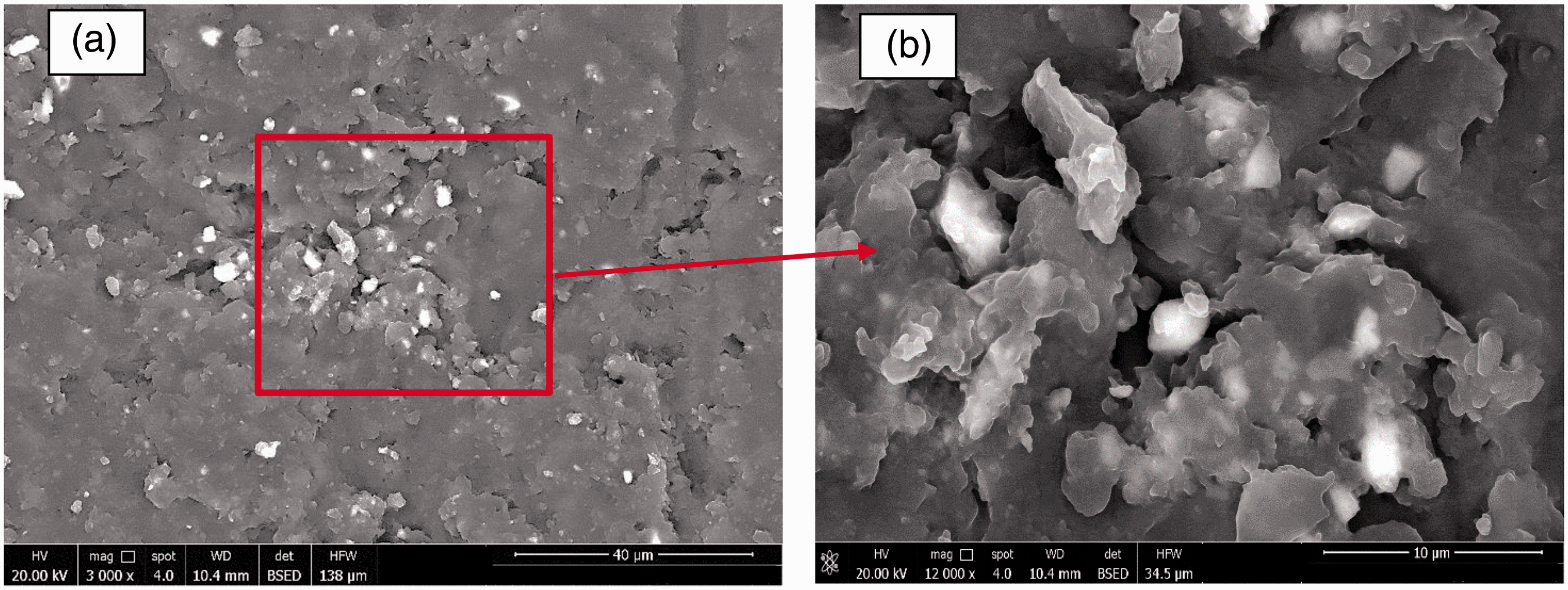
SEM of woven GFRE filled with 0.25 wt. % TiO2 nanoparticles with different magnifications of (a) X3000 and (b) X12000.

SEM of woven GFRE filled with 0.5 wt. % TiO2 nanoparticles with different magnifications of (a) X3000 and (b) X12000.
Table 4 shows the void content and properties of the fabricated composite laminate. The formation of voids in the composite laminates reduces the mechanical properties significantly. As shown in Table 4, the void content in GFRE filled with TiO2 nanoparticles is lower than unfilled GFRE composites. This can be due to the existence of TiO2 nanoparticles that fill the space into the voids during the fabrication of the composite laminates. Similar results were obtained by references [35,40,76]. The low void content in GFRE filled with 0.25 wt. % TiO2 nanoparticles reveals the good tensile and flexural properties compared with GFRE filled with 0.5 wt. % TiO2 nanoparticles as shown in Table 4. Further increase in TiO2 nanoparticles leads to an increase in void content.
Void content and properties of the fabricated composite laminate.

These voids work as stress concentration centers thus decreasing the tensile strength of GFRE filled with 0.5 wt. % as compared to GFRE filled with 0.25 wt. % TiO2 nanoparticles. The formation of these voids is due to the agglomeration of TiO2 nanoparticles as shown in Figure 16.
Hardness test
The hardness of HLT, neat and nanofilled woven and chopped GFRE of woven and chopped GFRE at different locations along the center of specimen is shown in Figure 17. It is clear from the figure that all the hardness of both neat woven and chopped composite laminates fabricated by the integrated vacuum technique is higher than that fabricated with HLT. A significant improvement of 132.8% in hardness was obtained with chopped composite laminates fabricated by the integrated vacuum technique as compared to that fabricated with HLT. However, an improvement of 16.4% in hardness is obtained with woven composite laminates as compared to that fabricated with HLT. This can be attributed to the removal of the gases inside the mold in the integrated vacuum technique.

Hardness of HLT, neat and nanofilled (a) woven and (b)chopped GFRE at different location along the center of specimen.
This figure indicates that the hardness is enhanced with the increase in TiO2 nanoparticles content with both woven and chopped nanocomposites. Similar findings also obtained by [2,77]. The improvement in hardness resulted from the incorporation of nanoparticles can be attributed to the high intrinsic hardness of the TiO2 nanoparticles. Furthermore, on the load applied from the indenter, an increase in compressive force achieved. Hence, this indenter presses the polymeric matrix, and then, fibers and fillers touch each other and possess resistance. Further increase in weight percent of nanoparticle content, nanoparticles fill in the gap present between glass fiber and epoxy matrix and form a more dense structure and thus hardness increases [78]. From Figure 18, it is clear that there are improvements in hardness of 14.48% and 24.9% were attained for woven GFRE filled with 0.25 wt. % and 0.5 wt % TiO2 nanoparticles, respectively as compared to woven GFRE. However, enhancements of 11.26% and 31.94% were attained in hardness for chopped GFRE filled with 0.25 wt. % and 0.5 wt. % TiO2 nanoparticles, respectively as compared to chopped GFRE.

Hardness of HLT, neat and nanofilled woven and chopped GFRE.
Conclusions
In this study, a cost-effective integrated vacuum infusion and resin transfer molding technique was developed. In this technique a semitransparent composite plate has the inverse shape of the produced laminate supersedes the vacuum bag, peel ply, distribution media, and breather. This semitransparent composite laminate gave a uniform thickness, smooth surface to the polymeric composite product. Moreover, it allows monitoring the resin flow during the infusion process. Also, it can withstand high temperatures and control the part thickness. The mechanical properties of neat composite laminates fabricated with this integrated technique were compared with that produced by the Hand Lay-up technique. Furthermore, the influence of incorporation of TiO2 nanoparticles with different weight fractions on tensile, flexural and hardness behavior of glass fiber/epoxy composites was studied. From the experimental results, the following conclusions were highlighted: The integrated vacuum infusion technique gives high tensile and flexural properties for both woven and chopped E-glass compared with hand layup technique. Incorporation of 0.25 wt. % TiO2 nanoparticles to woven and chopped GFRE laminates gave the highest tensile properties. Significant enhancements of 1.76%, 1.85%, 10% and 4.4% in tensile strength, strain to failure, Young’s modulus and toughness, respectively, were obtained in chopped GFRE filled with 0.25wt.% TiO2 nanoparticles as compared to neat chopped GFRE. However, significant enhancements of 31.1%, 5.47%, 10.29% and 35.7% in tensile strength, strain to failure, Young’s modulus and toughness, respectively, were obtained in woven GFRE filled with 0.25wt.% TiO2 nanoparticles as compared to neat woven GFRE. Incorporation of 0.25 wt. % TiO2 nanoparticles to woven GFRE laminates gives the highest flexural properties. However, incorporation of 0.5 wt. % TiO2 nanoparticles gives the highest flexural properties for chopped GFRE laminates. Significant enhancements of 105.3%, 23.8%, and 53.6% in flexural strength, flexural strain, and flexural modulus in chopped GFRE filled with 0.5wt. % TiO2 nanoparticles, respectively, as compared to neat chopped GFRE. However, significant enhancements of 16.8%, 3.4% and 37.7% in flexural strength, flexural strain, and flexural modulus were obtained in woven GFRE filled with 0.25wt. % TiO2 nanoparticles, respectively, as compared to neat woven GFRE. The hardness enhanced with the increase of TiO2 nanoparticles content for both woven and chopped nanocomposites. Improvements in hardness of 14.48% and 24.9% were attained for woven GFRE filled with 0.25 wt. % and 0.5wt. % TiO2 nanoparticles, respectively. However, enhancements of 11.26% and 31.94% were attained in hardness for chopped GFRE filled with 0.25 wt. % and 0.5wt. % TiO2 nanoparticles, respectively.
Footnotes
Declaration of conflicting interests
The author(s) declared no potential conflicts of interest with respect to the research, authorship, and/or publication of this article.
Funding
The author(s) received no financial support for the research, authorship, and/or publication of this article.