
Abstract
The present research reports the geometric model of four-directional 3D (4D3D) braided preform developed on four-step 3D braiding machine which consists of even and an equal number of yarn carriers in the rows and columns, respectively, on machine bed. The yarn path within the unit cell of the preform was analyzed to establish the correlation between surface braiding angle and interior braiding angle. A single unit cell model approach was used to predict the fibre volume fraction of the preform. It has been observed that the number of yarn carriers in the rows and columns is a critical parameter to decide the geometry of 4D3D braided preform. The fibre volume fraction predicted by the present model was compared with the three-unit cell model, multi-unit cell model and experimental results. A good agreement was observed between model computed results and experimental results.
Introduction
‘The four-directional 3D braided composites are more advantageous as a primary load-bearing component, compared to 2D laminates in terms of their mechanical properties, high impact energy absorption, impact damage tolerance, superior crashworthiness properties due to through-thickness reinforcement and potential to produce near net shape preforms inexpensively’ [1–3]. Further, low-cost methods such as resin transfer moulding and vacuum-assisted resin infusion can be used for 3D braided composite fabrication. Therefore, the 3D braided preforms have attracted the attention of the aeronautic, astronautic, automobile and marine industry. The 3D braided composites have possible applications in airframe spars, the tail shaft on aircraft, and propeller shafts on marine craft. Also, these composites can be used as drive shafts of automobiles [2,4,5].
The tubular and flat braids are produced by using a conventional braiding technique of 2D braids. Further, 3D braided preforms can be produced by using complex mandrels on conventional braiding. However, the 3D braided structures have through-thickness multidirectional interlacement which helps to reduce the delamination of their composites [6,7]. Therefore, 3D braids can be safely called as solid braids. 3D braids are classified as horn gear type [3,6] and track and column type (two-step and four-step braiding) [8,9]. The track and column type is sometimes called as cartesian braiding. The through-thickness interlacement in the 3D braided structure is achieved by a systematic shifting of carriers from one track to the other [8]. The arrangement of carriers in the 3D braiding machine can be circular [10,11] or cartesian [12]. The four-step 1 × 1 braiding principle to produce 4D3D braided structure is shown in Figure 1. In step one, alternate rows of carriers will be moved by one position. In step two, alternate columns of carriers will be moved by one position. Step three and step four are a repetition of step one and step two, respectively. The four-step 1 × 1 braiding principle enables laying of yarns in four different directions [13].

The four-step 1 × 1 3D braiding principle.
The internal structure of 3D braided preforms has received much attention compared to its external shape. The yarn topology in the 3D braided preform decides yarn orientation and fibre volume fraction of the preform [3]. The yarn topology changes with braiding method adopted such as surface-core braiding [14], multilayer braiding [10], multilayer interlock braiding [15], and orthogonal braiding [16]. The yarn topology also changes with the interlacement pattern, i.e. ‘1 × 1’, ‘1 × 2’, where the number indicates carrier movement in a single step in the row and column direction, respectively [8,17]. Three types of unit cell models of four-step 3D braided preforms have been reported, namely interior unit cell model [18,19], three-unit cell model [20–22], and multiunit cell model [1,12,23]. Xu and Qian [1] reported a multi-unit cell model of rectangular 4D3D braided preform to predict fibre volume fraction. They stated that the number of yarn carriers in the rows and columns affects the geometry of 4D3D braided preform. Another multi-unit cell model was reported by Mahmood and Mohammad [12] to study the effect of even and an odd number of yarn carriers in the rows and columns of the 3D braiding machine on the fibre volume fraction of preform. However, they did not compare the experimental and model-predicted fibre volume fraction. Li et al. [24] developed a geometric model of 4D3D braided preforms to predict the dimensions of a unit cell and fibre volume fraction. The model developed by them assumes the hexagonal cross-section of braider yarns. The model-predicted values have good agreement with the experimental results. However, they reported 4D3D braided preform produced on 3D braiding machine which has an unequal number of carriers in the rows and columns on machine bed. The 4D3D braided preform structure with equal and unequal number of yarn carriers is significantly different in terms of surface and interior preform geometry. The authors did an extensive literature survey and found that many studies reported a geometric model for the prediction of fibre volume fraction of 4D3D braided preform [25–30]. However, they either did not report about the effect of the number of carriers on 4D3D braided preforms fibre volume fraction or did not compare the experimental and model computed fibre volume fraction.
The fundamental problem associated with three-unit cell and multi-unit cell model is the complexity involved in the experimental measurement of fibre volume fraction of individual units of a unit cell and it may introduce prediction errors. Therefore, the present research is aimed to develop a single unit cell model (SUCM) of 4D3D braided preform produced on four-step 3D braiding machine which consists of even and an equal number of yarn carriers in the rows and columns and also to validate the model. The SUCM approach is novel because it is more realistic and the experimental determination of braid parameters using SUCM approach is easier and minimises the prediction errors.
Materials and methods
Materials
The E-glass fibres having linear density of 2400 tex, supplied by Owens-Corning Fibreglass Corporation, India were used for producing 4D3D braided preforms. The epoxy resin LY-556 and its curing agent HY-951 supplied by Northern polymers India were used to develop composite specimens.
Methods
The 4D3D braided preforms were produced on the four-step 3D braiding machine which is fabricated in our laboratory as shown in Figure 2. The machine has four rows and columns of carriers. The total number of carriers on the machine bed is 24. 4D3D braided preforms were produced by using three different surface braid angles namely 10.06, 16.28, 21.94°, respectively. The surface braiding angles were varied via take-up speed. The surface braiding angle and the unit cell height are measured by using a Nikon low magnification microscope. Thickness and fibre volume fraction of the preforms are measured according to the ASTM D1777-96 and D3776M-09a, respectively. In order to develop composite specimens, the epoxy resin and its curing agent were mixed in the weight proportion of 100:10 [31] and applied on to the braided preforms by using the hand lay-up technique. The composites were cured at room temperature for 24 h. The yarn path within the 4D3D braided structure was analyzed by cutting the composite along the yarn path.

Photograph of the 4D3D braiding machine.
Explanation of the geometric model
Basic assumptions
The 3D braiding machine consists of even and an equal number of yarn carriers arranged in the rows and columns, respectively, on machine bed. Therefore, the preform with square cross-section will be produced. All the yarns to be braided are of the same material, linear density and fibre volume fraction [12]. The braiding process is stable and the preform produced is uniform [12].
Correlations between preform geometric parameters
The 4D3D braided preform with square cross-section was analysed to determine the yarn path within the unit cell. The cured composite specimen was cut diagonally at two different positions (P-iiand P-iiias shown in Figure 4(d)) to study the yarn path in the unit cell as shown in Figure 3. It has been observed that all the yarns follow a straight-line path within the unit cell. A similar observation is reported by Fang et al. [32] for 4D3D braided preforms. The present model considers an equal number of yarn carriers in the rows (m) and columns (n) on machine bed. Therefore, the total number of yarn carriers will be m(m + 2) [12]. The total number of steps required for a carrier to complete one repeat will be 4(m + 2). Therefore, the length of one repeat unit will be h(m + 2), where his the unit cell height.

The 4D3D braided preform (a) and its composite (b); The sectional view of yarn path in the 4D3D braided composite showing yarn part P-ii(c) and yarn part P-iii(d).
The cross-sectional view of the yarn path in the repeat unit of 4D3D braided preform for four rows and columns of carriers on the machine bed is shown in Figure 4(d). There are four groups of yarn carriers namely G1, G2, G3, G4. The number of groups of yarn carriers formed is equal to the number of rows or columns of carriers on the machine bed. Each group contains (m + 2) the number of yarn carriers. All the carriers in a group follow a particular yarn path on a machine bed as shown in Figure 4(d). The repeat unit of the 4D3D braided preform was cut and the length of all the braider yarns was measured. It has been found that all the braider yarns have equal length which indicates that they are laid at an equal interior braiding angle with respect to braid axis. The geometry of the yarn path inside the repeat unit of 4D3D braided preform is shown in Figure 4(a)and the surface geometry of 4D3D braided preform and its model is shown in Figure 4(b) and (c), respectively.

(a) Repeat unit of the 4D3D braided preform showing yarn path in the repeat unit, surface braiding angle (β) and interior braiding angle (γ); (b) Surface geometry of the 4D3D braided preform; (c) Model of the surface geometry of 4D3D braided preform; (d) Cross-sectional view of yarn path in the 4D3D braided preform showing yarn parts P-ito P-ivand yarn groups G1 to G4.
The surface braiding angle βis measured between the line projected along the surface braider yarn axis XY up to half of the repeat unit and braid axis as shown in Figure 4(a). The thickness (a) of 4D3D braided preform is given as

From Figure 3(a), the interior braiding angle (γ) is given as
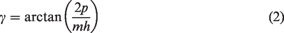

From equations (1)to (3), the interior braiding angle (γ) and the surface braiding angle (β) can be related as follows

The length of any individual yarn in the unit cell (l) is given as

Therefore, the total length of all the yarns in the unit cell (TL) is given as

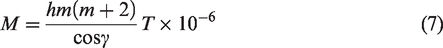
From equation (6), mass per unit length (M) of 4D3D braided preform is given as
The volume of the fibres (Vf) within the unit cell of 4D3D braided preform is given as

The total volume of the unit cell (VT) is given as

Therefore, the fibre volume fraction (φ) of 4D3D braided preform is given as

From equations (8), (9) and (10), the fibre volume fraction (φ) of 4D3D braided preform is given as

Results and discussion
Comparison of model-predicted and experimental results
The model computed and measured values of the geometric parameters such as interior braiding angle, the thickness of the preform, length of a single yarn in the unit cell and fibre volume fraction are shown in Table 1. A good agreement was observed between the model computed results and experimental results. The experimental and the model computed values of the fibre volume fraction were compared with the three-unit cell model reported by Li et al. [23] and the multi-unit cell model reported by Mahmood and Mohammad [12] as shown in Figure 5. It has been observed that the fibre volume fraction values obtained using by Li et al. model, Mahmood and Mohammad model and present model are comparable. Thus, the single unit cell approach can be used to model the geometry of 4D3D braided preform.
Model computed and the experimental results of 4D3D braided preform parameters.

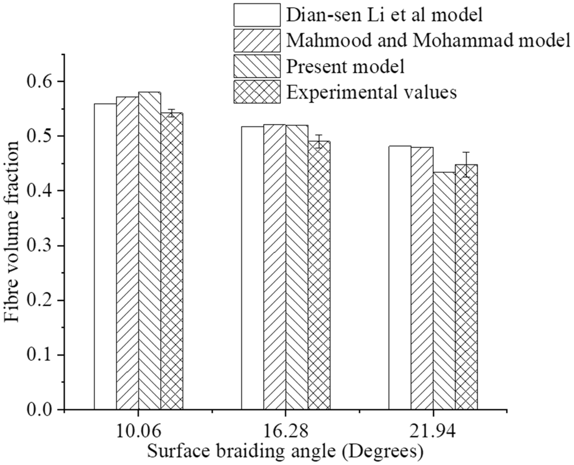
Comparison of fibre volume fraction obtained from Li et al. model, Mahmood and Mohammad model, present model and experimental values.
Effect of surface braiding angle on 4D3D braided preform parameters
As shown in Figure 6, keeping the unit cell height constant, as the surface braiding angle increases, the interior braiding angle also increases. This is due to the fact that at constant unit cell height and number of carriers on the machine bed, as the surface braiding angle increases, the braider yarn orients with an increase in the angle of inclination with respect to the braid axis, as a result of which the interior braiding angle increases. The surface braiding angle is measured between the line projected along the surface braider yarn axis up to half of the repeat unit and braid axis, which implies that the surface braiding angle changes with preform thickness. Therefore, with the increment in surface braiding angle, the preform thickness increases as shown in Figure 7. Further, as the preform thickness increases, the length of yarn in a unit also increases as shown in Figure 8. The similar observation is reported by Li et al. [24]. Furthermore, as depicted in Figure 6, with the increment in surface braiding angle, the fibre volume fraction of 4D3D braided preform decreases. This is due to the fact that when the surface braiding angle increases, the thickness of 4D3D braided preform increases. Hence, the total volume of the unit cell increases and the fibre volume fraction decreases. Therefore, the surface braiding angle is a critical geometric parameter of 4D3D braided preform and it ultimately decides the properties of the 4D3D braided composite to be produced.

Effect of surface braiding angle on interior braiding angle and fibre volume fraction (h = 10 mm).

Effect of surface braiding angle on interior braiding angle and preform thickness (h = 10 mm).

Effect of surface braiding angle on single yarn length in unit cell (h = 10 mm).
Effect of number of rows or columns of carriers on 4D3D braided preform parameters
As shown in Figure 9, keeping the surface braiding angle and the unit cell height constant, as the number of yarn carriers in the rows or columns of 4D3D braiding machine increases, the interior braiding angle decreases, and the fibre volume fraction increases. This is due to the fact that, as the number of yarn carriers increases, the preform thickness and the length of the repeat unit increase. Hence, the yarn length in the unit cell and the interior braiding angle decrease. Also, with an increase in the number of yarn carriers, the mass per unit length of the preform increases and hence the fibre volume fraction increases. However, no significant change in the interior braiding angle and fibre volume fraction was observed when the number of rows or columns of carriers crosses 20. Xu and Qian [1] for multiunit cell model of 4D3D braided preform reported that with an increase in the number of carriers on machine bed, the fibre volume fraction of interior unit cell increases. As shown in Figure 9, the interior braiding angle and the fibre volume fraction for 3D braided preform produced with 15° surface braiding angle, 10 mm unit cell height and 20 number of rows or columns of carriers on the machine bed will be 21.6° and 55%, respectively. Further, when the number of rows or columns of carriers on the machine bed reaches 50, the interior braiding angle and fibre volume fraction of the preform will be 21.1° and 58%, whereas the preform thickness will be 29 mm and 70 mm for 20 and 50 number of carriers in the rows and columns on the machine bed, respectively.
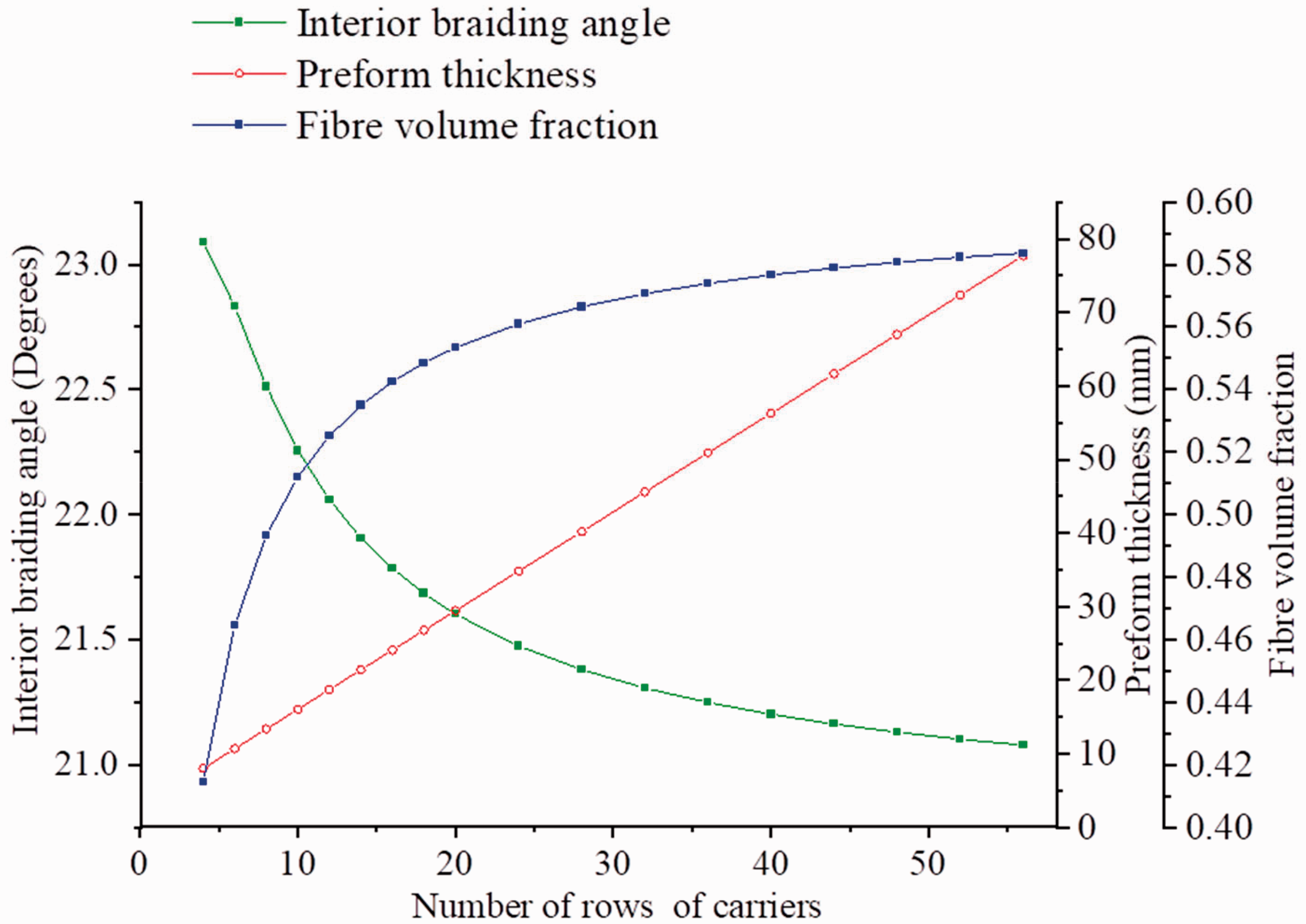
Effect of the number of yarn carriers in rows and columns on interior braiding angle, preform thickness and fibre volume fraction with changing the (β = 15° and h = 10 mm).
Conclusions
The developed geometric model considers even and an equal number of carriers in the rows and columns on 3D braiding machine bed and it is based on single unit cell approach. Therefore, the model presents a realistic way to study the geometry of 4D3D braided preform and thus it is novel. The number of yarn carriers in the rows and columns of four-step 3D braiding machine is one of the key parameters to decide braid geometry and hence the fibre volume fraction. The length of the repeat unit is decided by the surface braiding angle and the number of carriers in the rows or columns. The fibre volume fraction obtained by using the present model is comparable with the three-unit cell model and multi-unit cell model. Further, the SUCM approach can be extended to model the geometry of 4D3D braided preforms produced on the four-step 3D braiding machine which consists of an odd number of carriers in the rows and columns, respectively, on the machine bed.
Footnotes
Declaration of conflicting interests
The author(s) declared no potential conflicts of interest with respect to the research, authorship, and/or publication of this article.
Funding
The author(s) received no financial support for the research, authorship, and/or publication of this article.