
Abstract
In this research work, multi-layered composites of pure and hybrid woven fibre mats were fabricated using microwave-assisted compression moulding process. The hybrid composite consisted of jute and kenaf fibre as reinforcement having weight fraction of 29 ± 1%, while high-density polyethylene acted as the matrix. The laminate of multi-layered composites was fabricated by stacking the kenaf and jute woven fibre mats with high-density polyethylene matrix, resulting in different hybrid composites, i.e. JJJ, KKK, JKJ and KJK. JKJ exhibited maximum flexural strength of 55.64 ± 2.8 MPa, whereas KJK exhibited maximum flexural modulus of 3.65 ± 0.2 GPa. The tensile strength, impact strength and Shore D hardness were maximum in case of KKK composite, having the value of 60 ± 3 MPa, 31.8 ± 1.6 kJ/m2 and 58 ± 2.9, respectively. It can be concluded that the stacking sequence has a nominal effect on flexural strength, tensile strength and impact strength of the composites.
Introduction
Natural fibres have attracted attention as an alternative reinforcement for fibre reinforced polymer composites (FRPCs). Some of the unique attributes of natural fibres are low weight [1], good mechanical properties, high specific strength, low cost [2], bio-degradable and eco-friendly characteristics [3]. These composites can be used in fabricating various components, i.e. sports goods [4], automotive components [5], consumer goods [6], infrastructure application [7], etc. One of the promising applications of natural fibre reinforced composites is in infrastructural components, which has low to medium load-bearing capacity with appreciable damping characteristics [8]. Such composites can be used to fabricate walls and floors of houses in the seismically active zone regions, namely in Himalayan regions of India. Various types of natural fibres are available. A brief review has been done to explore the extent of use of these fibres. Natural fibres, such as kenaf [9], hemp [10], coconut coir [11], pineapple [12], abaca, flax, banana, sisal [13], bamboo [14], jute [15], etc., are copiously available in India. These fibres are widely used in textile industries to manufacture different products, i.e. carpet backs, wallboards, floor covering, mats, hats, baskets, rugs, upholstery, mattresses, etc. [16]. Additionally, these fibres are used to fabricate FRPCs. The reinforcements are available in the form of a woven mat, chopped fibre, knit and braid. The matrix material in FRPC may be thermoplastic or thermoset.
Sathishkumar et al. characterised hybrid composite of sisal/cotton fibre woven mat. Composite with 40 wt.% of sisal/cotton showed highest mechanical properties and vibration characteristics as compared to composite with 10 wt.%, 20 wt.%, 30 wt.% and 50 wt.% reinforcement [8]. This was because of the higher value of fibre/matrix interfacial strength. Saw et al. fabricated pure jute, pure coir and jute/coir hybrid composite and studied the mechanical and morphological properties [17]. It was observed that composite consisting of pure coir shows maximum water absorption and swelling thickness, whereas pure jute composite showed minimum water absorption and swelling thickness. From the water absorption and mechanical test, it was observed that the dimensional stability of jute/coir/jute composite was better as compared to coir/jute/coir composite. It was also observed that the hybrid composite consisting of a top layer of jute fibres showed better properties. This was due to the jute fibre acts as a barrier to prevent diffusion of water into the hybrid composite. Hassan et al. fabricated hybrid jute/betel nut composite and studied the mechanical performance [18]. It was found that by reinforcing beetle nut into 10% jute/polypropylene composite, the mechanical properties of the hybrid composites were improved. Aji et al. fabricated kenaf/pineapple leaf reinforced high-density polyethylene (HDPE) hybrid composite and studied the mechanical properties and water absorption behaviour [12]. It was observed that composite having a higher aspect ratio of kenaf fibre showed better mechanical properties.
Manufacturing of polymer composite material is of a great challenge. There are different techniques used to fabricate composite materials such as injection moulding, compression moulding, autoclave, etc. The motive of the composite manufacturing industry is to fabricate the composites in a cost-effective and environment-friendly way [2]. Recently, the use of microwave energy to fabricate polymer composites has received considerable attention [19–21]. Microwave energy is an efficient route to process materials based on the type of interaction. Dielectric and magnetic properties significantly influence microwave material interaction characteristics [22]. Microwave energy is an efficient route to process materials based on the type of interaction. Dielectric and magnetic properties significantly influence microwave material interaction characteristics [22]. Microwave interaction of polymer composites mainly depends on the dielectric properties of the polymer matrix and reinforcement. The popularity of microwave energy for fabricating polymer composites is due to uniform heat distribution, small process cycle time, less in-process scrap, enhanced mechanical properties, etc. [4,23–25].
After a detailed review of the literature, it was observed that very less work done related to the hybridisation of different natural fibres. Most of the fibre (natural and synthetic) hybridisation works were done using conventional fabrication techniques. As per the knowledge of authors, there is no literature available on the fabrication of hybrid composites using microwave-assisted compression moulding (MACM). Therefore, the objective of the present work is to fabricate kenaf/jute hybrid composites using MACM and investigate the effect of stacking sequence on the mechanical performance of composites. Four types of composite were fabricated with different stacking sequence, i.e. JJJ, KKK, JKJ and KJK. The mechanical performance of the composites was studied in terms of tensile strength, flexural strength, impact strength and Shore D hardness and results were supported using scanning electron microscope (SEM) fractographs.
Materials and methods
Materials
Present work deals with HDPE as a matrix material. The HDPE was sourced in the form of pellets (HDPE-50MA180) from Reliance Chemicals, Mumbai, India. The kenaf and jute fibre mats of 200 GSM were sourced in the form of mat Go Green Products, Chennai, India. The woven fibres were of the plain weave 0/90 pattern. The properties of constituent material used to fabricate the composite are shown in Table 1 [7,26]. The length, width and thickness of the unit cell of kenaf fibre were 140, 12.5 and 0.10 mm, respectively, whereas in the case of jute fibre, the length and width of the unit cell were same as of kenaf fibre; the only difference was in the thickness of the unit cell (i.e. 0.11 mm).
Physical properties of constituent materials used during hybrid composite fabrication.

HDPE, high-density polyethylene.
Methods
Treatment of natural fibres
Prior to composite fabrication, it is essential to transform the hydrophobic nature of the natural fibres to hydrophilic to ensure proper wetting of fibre with the polymer matrix. Hence, to enhance the surface wettability, woven fibres were treated with NaOH solution of 10 wt.% to remove the dirt, wax, pectin, etc. [27]. The woven fibre mats were soaked in the NaOH (alkali) solution for 4 h at 27 ± 2°C. After alkali treatment, the soaked mat was washed in running tap water to remove traces of NaOH. Air at 60°C was used to remove moisture from the alkali-treated fibre mat in a hot oven drier for a minimum of 24 h. The surface roughness of kenaf and jute fibre were measured before and after the alkali treatment using optical profilometer (BRUKER; Model: CONTOURGT-K Automated System). The surface roughness of kenaf and jute fibres was 5.3 and 4.0 µm, respectively, before alkali treatment. After the alkali treatment, the surface roughness of kenaf and jute fibre was 6.7 and 4.5 µm, respectively.
Fourier transform infrared spectroscopy (Agilent Technologies; Model: K8002AA carry 660 FTIR) of alkali-treated fibres and untreated fibres were carried out in the range of 400 to 4000/cm. FTIR spectra of untreated and treated jute and kenaf fibres are shown in Figure 1(a) and (b), respectively. Both the fibres exhibit a similar trend in the FTIR analysis. The transmittance peaks seen in treated jute fibre near 1452, 1374 and 1035/cm are ascribed to –CH asymmetric, –CH3 symmetric stretching and aromatic –CH in-plane deformation in lignin, respectively. The absorbance band at 1738/cm is for C = O stretching vibration of the ester and carboxyl groups in hemicellulose fibre, which is prominent in raw jute fibre. A shoulder and a medium sharp peak arose at 1650 and 1630/cm due to absorbed water. The typical peak at 1450/cm corresponds to –CH2 bending of cellulose that remains unaffected after alkali treatment. From FTIR spectroscopy, it was observed that there is no effect of alkali treatment on the cellulose content, which could be the reason for the improvement of mechanical properties of FRPCs.

Fourier transform infrared spectra of untreated and treated (a) jute and (b) kenaf fibres.
Fabrication of composites
In this work, pure and HFRPC were fabricated using the MACM process. Pre-weighted pellets of HDPE were used to fabricate sheet of size 140 × 57 × 1.3 mm using MACM. Woven kenaf and jute fibre mats were alternately stacked between the HDPE sheets and put in an alumina mould of size 150 × 67 × 19 mm. The alumina mould containing stacked layers of woven kenaf/jute fibre mat and HDPE sheets were placed in a multimode industrial microwave applicator (VB Ceramics, Chennai; Model:700 DEG °C Premium). Alumina mould was used due to its chemical inertness, microwave transparency (up to 600 °C) and excellent surface finish [28]. During the fabrication of hybrid composites, compression pressure of 0.02 MPa was applied by applying a deadweight of 0.002 kg/cm2. The detailed setup of the MACM process and the stacking sequence is schematically illustrated in Figure 2. Details related to parameter optimisation and fabrication are discussed elsewhere [4]. The size of the composites obtained was 140 × 57 × 6.7 mm.
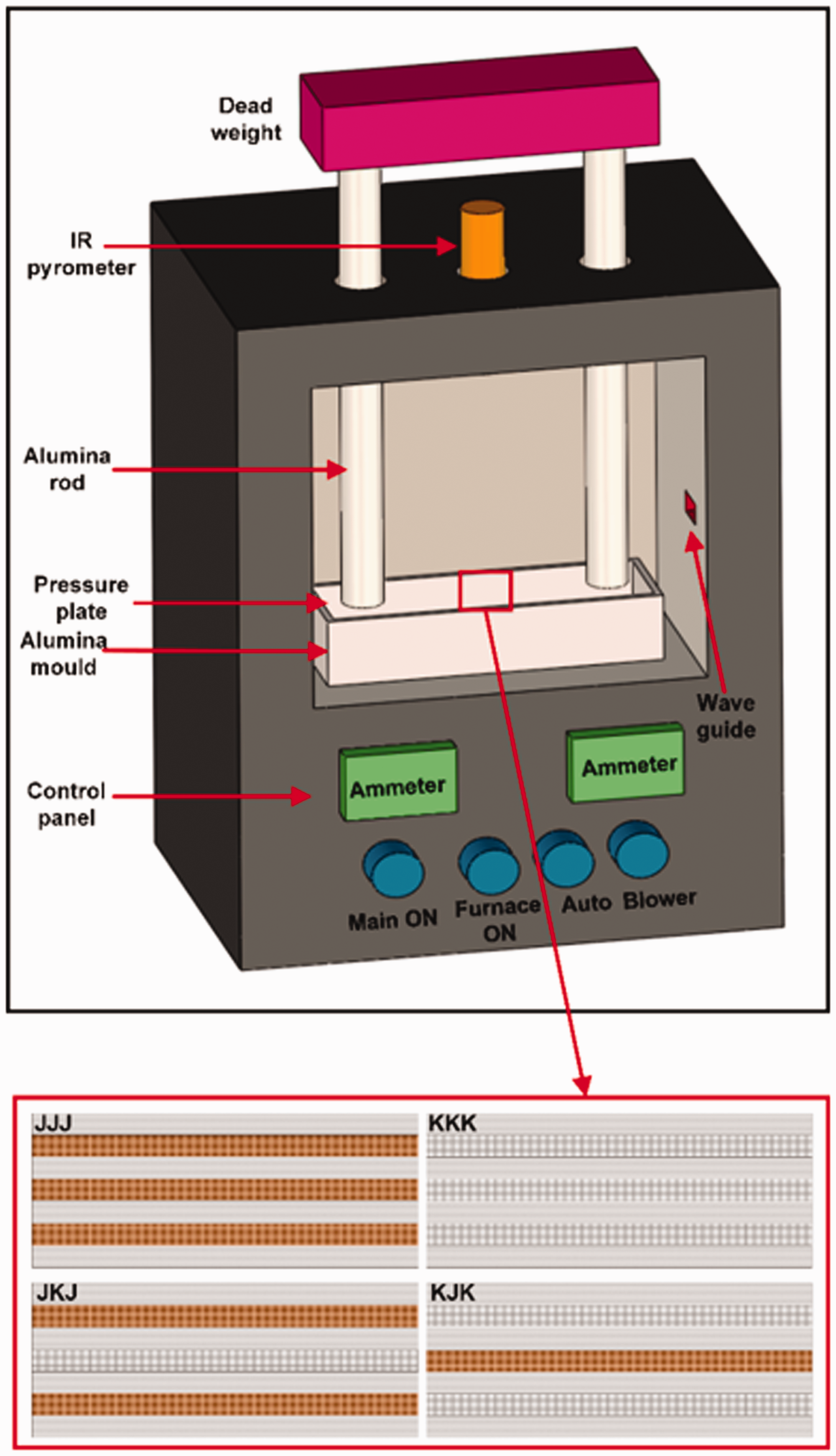
Microwave-assisted compression moulding setup for the fabrication of composites.
Mechanical testing
The composites were placed in hot oven dryer at 27°C for 24 h before performing the mechanical tests. Mechanical tests of the composites were performed in terms of flexural strength, impact strength and Shore D hardness. For reproducibility of the test data, five samples of each specimen were considered to compute the average and standard deviation values.
Flexural strength of the specimens was obtained on a three-point bending fixture on the universal testing machine (Tinius Olsen, UK; Model: H50KS). Specimen width of 12.5 mm and span length of 107.2 mm was taken as per ASTM standard D7264, during the flexural test. Similarly, for tensile test on the same machine, ASTM D3039 standard was taken. The load cell of 10 kN and a crosshead speed of 1 mm/min was used during both the tests.
Impact test was performed using Izod/Charpy impact tester (Advance Equipments, Mumbai; Model: AE-ICIT). ASTM standard D256 was used to prepare the Izod impact specimen of size 64 × 12.7 mm and notch width of size 2.4 mm. The load cell of H4 (15.3 N) was used during the impact test.
Hardness is a measure of resistant to localised plastic deformation induced by mechanical indentation or abrasion. The hardness of composites (H) can be expressed in term of the load applied (F) and projected indented area (S) as shown in equation (1) [29]
Hardness test was performed as per ASTM D 2240 standard using a Shore D hardness tester (Advance Equipments; Model: AE-SF-A). The load of 49 N and dwell time of 5 s was used during the hardness test.
Results and discussion
Microwave heating mechanism of composites
Figure 3(a) shows the time–temperature (TT) curve of HDPE pellets, jute and kenaf fibre, obtained to confirm the microwave heating feasibility during composite fabrication. The microwave interaction of non-magnetic material increases as the dielectric constant increases. It can be observed from Figure 3(a) that the microwave-assisted heating of kenaf and jute fibre is faster as compared to the HDPE pellets. This is because the higher value of dielectric constant (3-6) of these fibres, while in the case of HDPE pellets the dielectric constant is 2.26–2.4 [4]. The fundamental concept behind microwave-assisted heating is the transfer of electromagnetic energy at the molecular level. Dielectric polarisation mechanism plays a significant role in microwave-assisted heating of polymer composites. In the presence of alternating applied electromagnetic field, the dipoles in the target material try to orient themselves with the applied field as shown in Figure 3(b). Under the influence of the high frequency of the applied field (2.45 GHz), a phase lag is created between the dipoles. Inertial, elastic, frictional and molecular interaction forces resist these frequent changes in orientations of diploes that increase molecular kinetic energy and result in volumetric heating. The kinetic energy increase of all dipoles in the material increases the temperature of the material within a short time [30]. The heat generated in the reinforcement then gets conducted into the HDPE matrix and results in the fabricated composites as shown in Figure 3(b). Complex permittivity (ε*) is the main parameter on which microwave heat generation of non-magnetic material depends [31], which can be obtained using equation (2) [20]

(a) Time–temperature curve and (b) microwave heating mechanism in natural fiber reinforced polymer composites.
The microwave energy (
The volumetric power loss from composites during dielectric heating is governed by electric field heating equation (4) [20]
The effective dielectric loss factor (
In the case of dipoles, the complex permittivity can be separated into real and complex variables and expressed as equations (6) and (7) [20]

The relaxation time of molecules can be determined by the hindrance created during molecule reorientation in the presence of the applied alternating electric field. The dependence of molecular vibration’s temperature on relaxation time (τ) can be defined with the help of the Arrhenius equation as shown in equation (8) [4]
Equation (8) shows the exponential nature of microwave heating of composite materials. The exponential trend of microwave heating confirms the rapid heating of the composites as compared to conventional thermal heating. The alkali-treated fibres may create complicated dielectric behaviour, and as a result, it may result in additional interfacial and ionic bonding.
Figure 4(a) shows the stages of heating mechanism for one of the composites, i.e. JKJ hybrid composite. Optical image of HDPE pellets, jute and kenaf fibres are shown in Figure 4(a). The schematic of a stacked layer of HDPE, jute and kenaf fibres are shown in Figure 4(a). The inset of the stacked layer is used to visualise the stages of composites fabrication (Figure 4(a)). The parameters used during kenaf/jute hybrid composite fabrication are shown in Table 2. The values of parameters were obtained using the trial and error method. The time–temperature–pressure (TTP) curves for composites of various stacking configurations are shown in Figure 4(b). Stage I in Figure 4(a) shows the stacked layers of reinforcement and HDPE pellets placed in the microwave applicator. Stage II shows microwave heating of fibre reinforcement and heat transfer from the heated reinforcement to the HDPE matrix. In Stage III, HDPE matrix reaches the glass transition temperature and pressure of 0.02 MPa was applied using the dead weight for proper interfacial bonding between the reinforcement and matrix. In Stage IV, microwave power was switched off and the fabricated composite was allowed to reach room temperature. The constant pressure of 0.02 MPa was maintained during Stage III and Stage IV as shown in Figure 4(b). It is interesting to note that the cycle time for microwave processing was only 6% of the conventional autoclave curing [32]. Also, because of volumetric heating, the intermolecular bonding will be enhanced, and as a result, the mechanical properties of the composite will increase.

(a) Typical schematic of the stagewise heating mechanism and (b) time–temperature–pressure curve during microwave-assisted compression moulding of hybrid composites.
Optimised process parameters for microwave processing of kenaf/jute hybrid composites.

Density of fabricated composites
The theoretical density of fabricated composites was measured based on the density of HDPE, kenaf and jute fibre as 0.97, 1.4 and 1.3, respectively. Theoretical density (
The actual density (ρa) of the composites can be determined using Archimedes method. Thus, the volume fraction of voids present in the composites can be calculated using equation (10). Table 3 shows the different physical properties of hybrid composites fabricated through MACM. The fibre volume fraction in Table 3 shows the range of fibre reinforcement because of different diameter and density of the fibres.
Different physical properties of hybrid composites fabricated through microwave-assisted compression moulding.

Flexural test
Figure 5 shows the effect of fibre sequencing on the flexural properties of various specimens. Figure 5(a) shows the load–displacement curve of the specimens. The flexural strength of the KKK configuration was 54.33 ± 2.7 MPa (Figure 5(b)), which is comparable to the flexural strength of composite fabricated through compression moulding [33]. The flexural strength of the KKK configuration was 8.4% higher than the JJJ configuration. This may be due to the higher strength of the kenaf fibre as compared to jute fibre [4]. From Figure 5(b), it can be observed that the highest flexural strength was obtained in case of JKJ hybrid composite, which was 37.8% higher than KJK hybrid composite.

(a) Load–displacement curve and (b) flexural strength and flexural modulus as a function of layering sequence.
By replacing one layer of jute fibre in JJJ stacked composite with kenaf fibre (JKJ configuration), flexural strength increases by 11%. This indicates that kenaf fibre exhibits appreciable interfacial bonding between the outer layer of jute fibre mats. The reason behind this could be the increased surface roughness of the kenaf fibre after alkali treatment. Another reason may be due to reduction in void fraction, i.e. the void fraction of JKJ composites were reduced by 25.43% by incorporating one layer of kenaf fibre within JJJ composites (Table 3), whereas when one layer of kenaf fibre mat was replaced from KKK to hybridise it as KJK composite, the flexural strength decreases by 25.67%. The decrease in flexural strength of KJK hybrid composite may be because of jute fibre mat acts as a barrier in bonding between the outer kenaf fibre mat layers on both sides. This is because the surface roughness of the jute fibre mat was 32.8% less than the kenaf fibre mat. Additionally, the void fraction of KJK composite is increased by 13.63% as compared to KKK composites. Also, from the SEM image (Figure 6(a) and (b)), it can be observed that the interfacial bonding between jute fibre and HDPE matrix was not perfect in JJJ composite compared to KKK composite. From Figure 6(c), it can be observed that fibre bridging takes place during flexural failure, which may be the reason for the higher value of flexural strength of JKJ hybrid composite. Figure 6(d) shows the SEM fractograph of KJK hybrid composite. It can be observed from Figure 6(d) that there is some fibre kink present that may be the reason of flexural failure because of the brittle nature of fibre kink. Figure 6(d) also shows the improper adhesion between the HDPE matrix which creates tensile fracture with an interlaminar fracture.

Scanning electron microscope fractographs of flexural fractured (a) JJJ, (b) KKK, (c) JKJ and (d) KJK configuration composites.
The various modes of flexural failure are shown in Figure 7; however, in the present study, the flexural failure occurs mainly due to type (c) and (d). In Figure 7(c), tensile fracture of the outer surface takes place, whereas in Figure 7(d), tensile fracture with interlaminar shear takes place. Composites with good interfacial bonding show a tensile fracture of the outer surface. Thus, KKK and KJK configuration shows a tensile fracture of the outer surface. Tensile fracture with interlaminar fracture was exhibited in JJJ and JKJ composites.
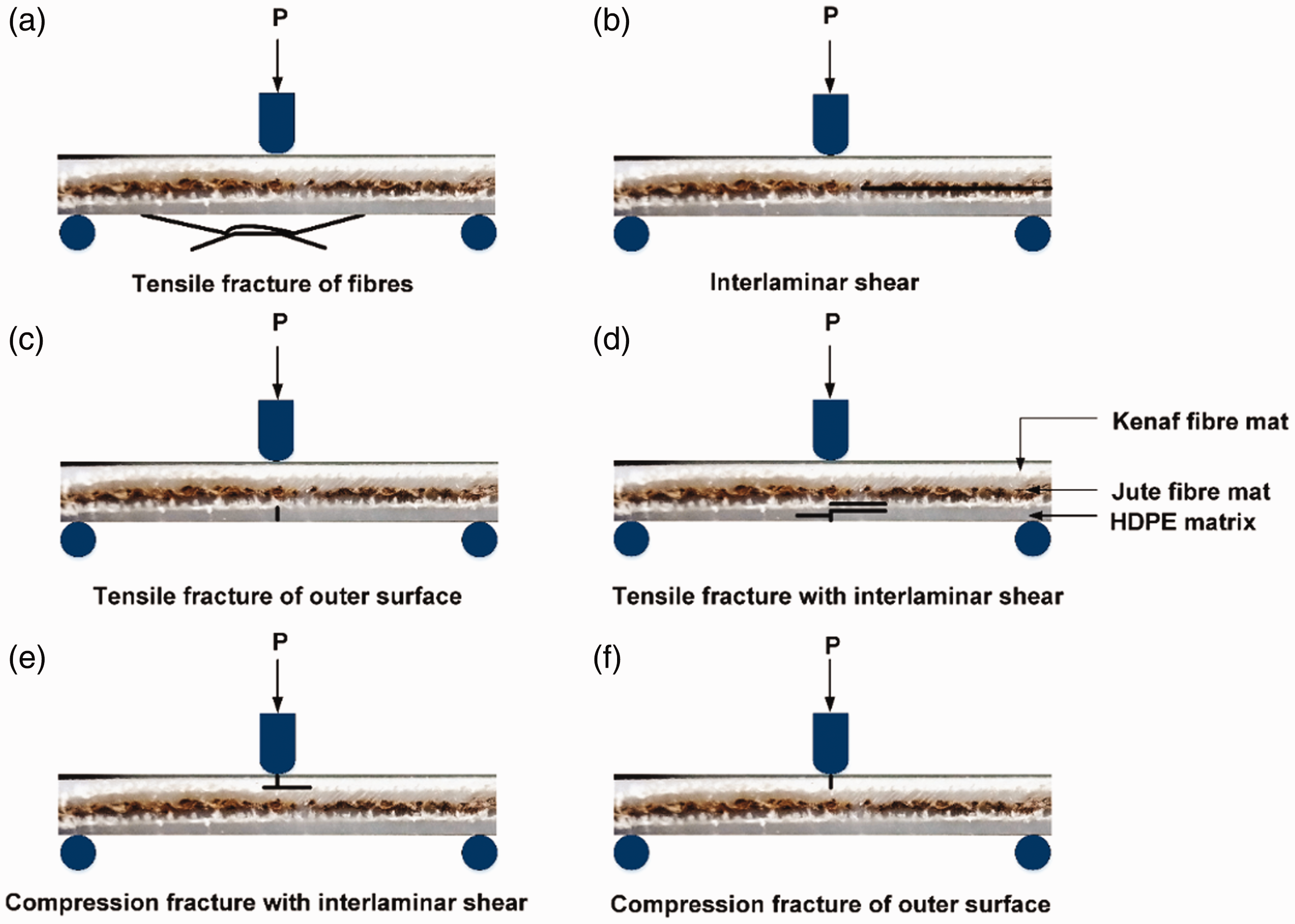
Schematic for possible flexural failure modes in composites.
Equation (11) can be used to calculate the flexural modulus of the composites.
The flexural modulus was maximum in case of KJK configuration (3.65 ±0.2 GPa) as comparable to the work of other researchers [34]. The lowest flexural modulus was obtained in case of JJJ composite. It can be observed from Figure 5(b), by hybridising the JJJ and KKK composites to JKJ and KJK hybrid composite, respectively, the flexural modulus increased by 4.7% and 17.7%, respectively. But the increment of flexural modulus was more in case of KJK stacked composite as compared to JKJ stacked composite. It is interesting to note that the hybrid composites having outer side layer of kenaf fibre mat showed better flexural modulus as compared to the composites having outer side layer of the jute fibre mat. This may be due to the stiff kenaf fibre. Kenaf fibre is stiffer than the jute fibre because of the higher value of lignin content present in the kenaf fibre. The higher lignin content acts as a good bonding agent for cellulose and provides stiffness to the fibre [35].
Tensile test
Figure 8 shows the stress-strain plot of different configured hybrid composites. It can be observed that the tensile strength of KKK and JKJ configured composites shows the maximum tensile strength of 60 ± 3 MPa. Additionally, the effect of hybridisation can be seen, as the tensile strength of the JKJ composite increased to 60 ± 3 MPa from 49.75 ± 2 MPa on replacing one layer of jute fibre with kenaf fibre in JJJ composite. The increase in tensile strength may be due to the void fraction in case of JJJ composite (1.14%) was higher than JKJ composite (0.85%). Same can be seen in SEM fractographs of tensile fractured composites in Figure 9(a) and (c). The decrease in the void fraction in JKJ composite after replacing jute fibre with kenaf fibre may be due to the higher roughness of kenaf fibre as compared to the jute fibre. This higher roughness of kenaf fibre helps in enhancing the interfacial bonding between the fibre and matrix. Considering KKK and KJK configured composites, it can be observed that the tensile strength of hybrid composite, i.e. KJK decreases by 7.3% when the intermediate layer of KKK composite replaced with jute fibre layer. This may be due to the void fraction in the KJK composite was higher than the KKK composite. This can be evidence in SEM fractographs of Figure 9(b) and (d). From Figure 9, it can also be observed that the kenaf fibres were elongated and less cracked as compare to jute fibres. Thus, it can be concluded that when kenaf fibre acts as the tensile load transfer medium, composite shows better tensile properties. This may be because the tensile strength of kenaf fibre (930 MPa) is more as compared to jute fibre (393–773 MPa) [36].

Stress–strain plot of different configured hybrid composites.

Scanning electron microscope fractographs of tensile fractured (a) JJJ, (b) KKK, (c) JKJ and (d) KJK configuration composites.
Impact test
Impact strength of JJJ, KKK, JKJ and KJK hybrid composites are 21.1 ± 1, 31.8 ± 1.6, 23.3 ± 1.2 and 27.7 ± 1.4 kJ/m2, respectively. The obtained impact strength for JJJ stacked composite was better as obtained by other researchers [18,37]. Composite consisting of only kenaf fibre, i.e. KKK, exhibited a higher value of impact strength. Composite of pure jute fibre shows a minimum impact strength of 21.1 ± 1 kJ/m2. The higher value of impact strength of KKK stacking sequence can be attributed to the good interfacial bonding between kenaf fibre and HDPE matrix, which may be due to higher surface roughness of kenaf fibre after alkali treatment as compared to jute fibre. Another observation from Table 3 was that, as the void fraction in the hybrid composite increases, the impact strength decreases.
Debonding, pull-out and fracture of fibre were the three mechanisms occur during impact loading on the stacked composites. The debonded length is the main factor on which strain energy released by fibre debonding and fracture depends. To resist the impact energy, the matrix tries to rotate, stretches or otherwise move. These phenomena occur at the molecular level and diffusion of energy will take place in the local area. This may be sufficient to create impact fracture. Therefore, to avoid the impact fracture, it is better to spread the energy in both constituents, i.e. matrix and fibre.
The effect of hybridisation can be observed from the data of impact strength. When one layer of kenaf fibre is placed into the jute fibre composite (JKJ configuration), the impact strength increases by 9.4%. Similarly, when one layer of kenaf fibre is replaced with jute fibre in KKK stacking sequence, its impact strength decreases by 12.9% (KJK configuration). It was also observed that the impact strength of KJK stacking sequence was higher as compared to the JKJ stacking sequence. This may be due to the poor adhesion between fibre and matrix, which leads to higher energy absorption [38]. The reason behind this could be the lesser increment in surface roughness of the jute fibre mat after alkali treatment as compared to the kenaf fibre mat. Jute fibre mat act as a barrier in bonding between the outer kenaf fibre mat layers on both sides of KJK hybrid composite. This may be because the surface roughness of the jute fibre mat was 32.8% less than the kenaf fibre mat. Another reason of higher impact strength of KJK composite as compared to JKJ could be due to the debonding length of KJK composite was higher as compared to JKJ composite. Additionally, it was also observed that as the reinforcement percentage of kenaf fibre increases in the hybrid composite, the impact strength increases.
Figure 10 shows the SEM fractographs of the impact fractured composite specimens. Broken fibres and rupture in the matrix are visible throughout the fractographs. The lowest value of impact strength among the fabricated composites was due to the bigger voids and lower wettability of jute fibre as shown in Figure 10(a). From Figure 10(b), good interfacial bonding can be observed between the kenaf fibre and HDPE matrix. The rough surface of the matrix is also seen in Figure 10(b), which was helpful in creating good interfacial bonding. Also, the bunch of fibres is seen, which act as fibre bridging during impact load. This fibre bridging transfers the energy from fibre to the matrix. The above-mentioned observations for Figure 10(b) support the higher value of impact strength of KKK stacking sequence. Figure 10(c) and (d) shows the SEM fractographs of JKJ and KJK hybrid composite, respectively. From Figure 10(c), it can be observed that there was adhesion between kenaf fibre and HDPE matrix, which leads to a lower value of impact energy as compared to KJK stacked composite. Figure 10(d) shows the gap between kenaf fibre and matrix. The imprints of kenaf fibre were also observed on the surface of KJK composite. These imprints are due to fibre pull-out due to debonding during impact failure.
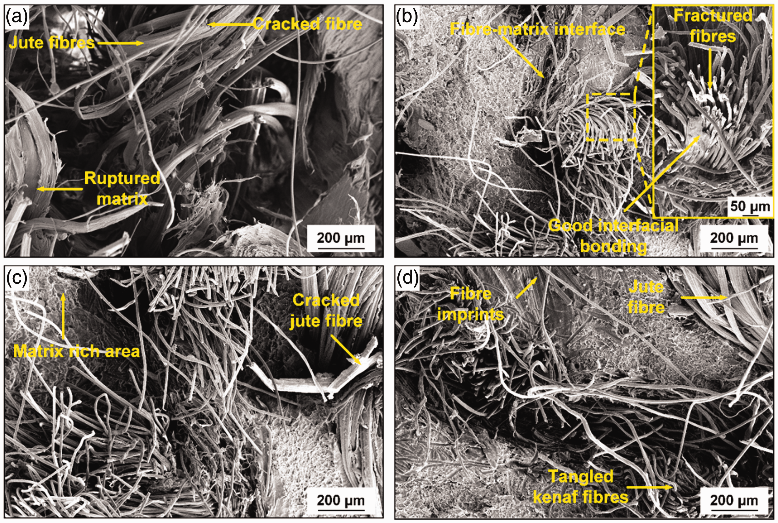
Scanning electron microscope fractographs of impact fractured (a) JJJ, (b) KKK, (c) JKJ and (d) KJK configuration composites.
Hardness test
The hardness of the neat HDPE was 48 ± 2.4 and for the tribological and other commercial applications of the composites higher hardness is required. Therefore, to increase the hardness, kenaf and jute fibre mats were stacked into the HDPE matrix. Thus, the least increase in the hardness of the neat kenaf/jute hybrid composite was observed as 11.9%. The Shore D hardness value of JJJ, KKK, JKJ and KJK hybrid composites are shown in Figure 11. It can be observed that the Shore D hardness of KKK configuration is highest among all the fabricated composites. This may be due to the higher value of lignin content present in the kenaf fibre (15%–19%) as compared to jute fibre (12%–13%). Lignin acts as a good bonding agent for cellulose and provides the stiffness to the fibre [39]. The Shore D hardness obtained for KKK and JJJ configuration was better than the composite fabricated using conventional thermal curing [40,41]. The KKK configuration exhibited 8% higher hardness as compared to the JJJ stacked composite. Hybridisation effect was studied from the data obtained for different composites. On replacing one layer of jute fibre from JJJ composite with kenaf fibre, the value of hardness of JKJ hybrid composite increased by 1.5%. Similarly, in the case of KJK, hybrid composite hardness decreased by 1.5%. From the study of hybridisation, it can be observed that there is a negligible effect of hybridisation on the hardness of hybrid composites. Additionally, it was also observed that as the void fraction increases, the hardness of the composite decreases.
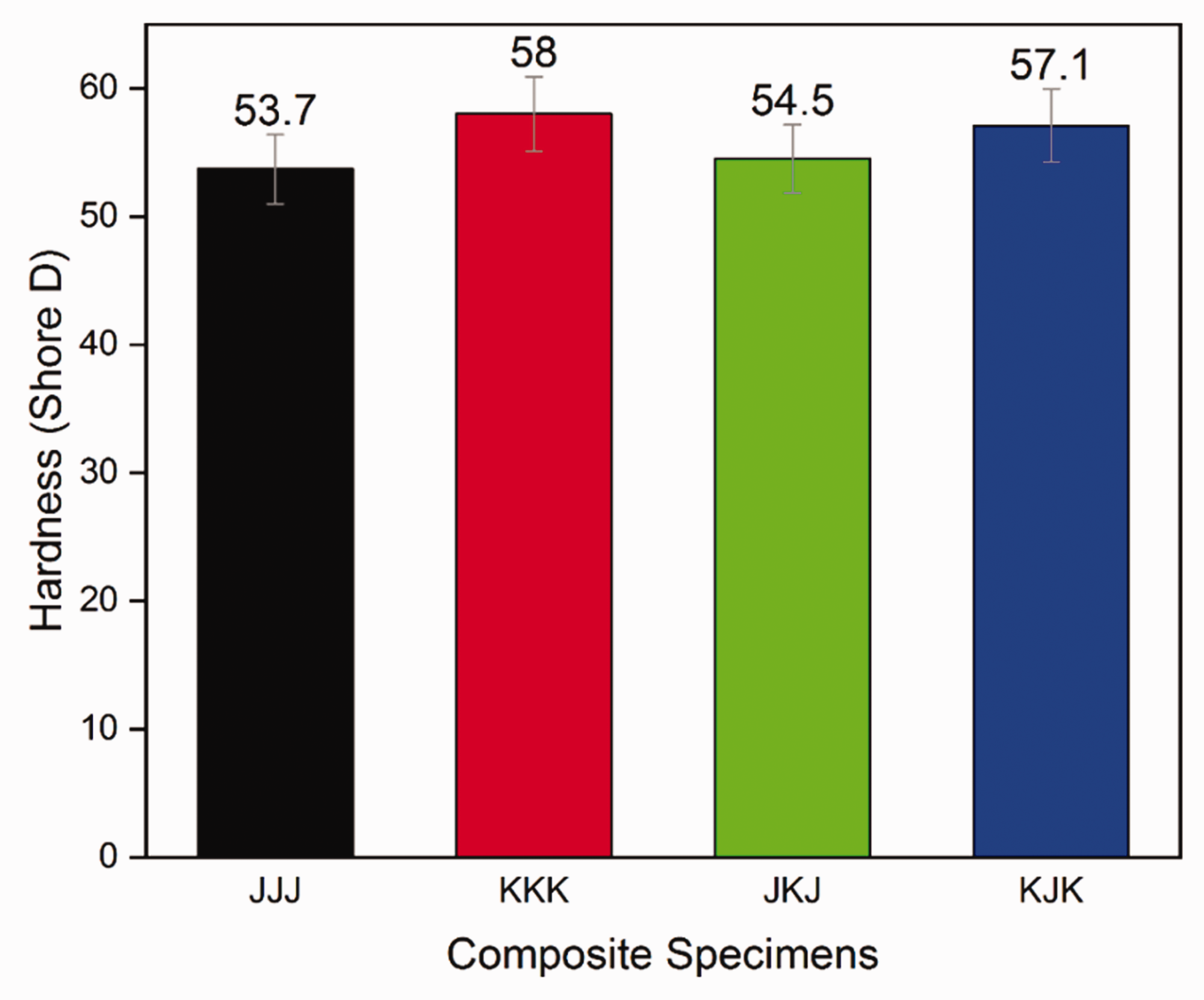
Shore D hardness of different stacked hybrid composites.
Conclusions
In the present work, kenaf/jute hybrid composites were fabricated using the MACM process. The composites fabricated through MACM have the capability to become a future alternative of conventional compression moulding. As the mechanical properties of these composites are either comparable or better than the composites fabricated through other techniques. Apart from comparable/better mechanical properties, this technique of fabrication is more energy-efficient than a conventional one.
Flexural strength of the JKJ configuration composite was highest among the stacked composites (55.64 ± 2.8 MPa), whereas in the case of kenaf/jute homogeneous composites, flexural strength was maximum in KKK stacked composite (54.33 ± 2.7 MPa). The flexural modulus was maximum in case of KJK configuration composite (3.65 ± 0.2 GPa). In the case of tensile strength, impact strength and Shore D hardness, the maximum value was obtained in KKK composite (60 ± 3 MPa, 31.8 ± 1.6 kJ/m2 and 58 Shore D, respectively). Effect of stacking was also observed, on the replacement of jute fibre mat from JJJ configuration composite with kenaf fibre (JKJ configuration composite), the tensile and impact strength increased by 20.6% and 9.4%, respectively. In the case of the Shore D hardness test, the effect of hybridisation was encouraging in JKJ configuration composite and adverse in case of KJK configuration. The results revealed that the influence in mechanical properties after hybridisation was up to 25.67%, although the influence in mechanical properties was nominal. But the hybridisation of composites using natural fibres of higher properties can enhance the properties of composites better. Nevertheless, the composite fabricated in present research work can be used in various low load applications, i.e. roofing, car indoor panels, seat cover panels, doors, mobile covers, table, chair, instrumental body, writing board, etc. These composites can be helpful in reducing the carbon footprint.
Footnotes
Declaration of conflicting interests
The author(s) declared no potential conflicts of interest with respect to the research, authorship, and/or publication of this article.
Funding
The author(s) disclosed receipt of the following financial support for the research, authorship, and/or publication of this article: The first author acknowledges the financial support in the form of monthly scholarship received from Ministry of Human Resource and Development, Government of India, for his PhD work.