
Abstract
This paper presents a textile-based thermoelectric generator (T-TEG) with 105-pair thermocouples fabricated from carbon fibers as basic material. The carbon fiber used in this study was in a tow form which contains 3000 filaments. This tow was inserted into polyester fabric by hand to form a series of float yarns on the fabric. After acetone treatment, roughly every half of the floats on both sides of the fabric was covered by acrylic dispersion to resist nickel particles during electroplating in order to get a chain of carbon-nickel thermojunction. After the acrylic dispersion was completely polymerized, the sample was electroplated in the plating solution containing nickel acetate, boric acid, and sodium dodecyl sulfate. Subsequently, the sample was washed and dried. This T-TEG was fabricated on a small piece of fabric around 12 cm × 12 cm which contains 105-pair of carbon fiber and nickel-coated carbon fiber forming a thermopile. To study its electrical properties, this T-TEG was characterized to obtain the voltage-temperature curve, the voltage-current characteristic, the output power versus current and the maximum power versus temperature. Characterization results of this T-TEG show characteristics of a typical thermoelectric generator. Scanning electron micrograph images and EDS spectra were also examined to see the nickel deposition on the carbon fiber surface.
Introduction
The problems with fossil fuels are limited availability and high price [1]. For that reason, the so-called ambient energy such as solar, wind, thermal, kinetic energy, etc. has been gaining more attention to be utilized nowadays. The thermoelectric generator offers an environmentally friendly solution to harvest renewable energy from waste heats by converting it into electric energy. Furthermore, a thermoelectric generator is different from other electric generators since there are no moving parts involved in the system making the operation noiseless [2].
In their review, Makimoto and Sakai [3] summarised that the development of semiconductor technology has had a big impact on electronic performance, function, size and particularly power dissipation. Many types of electronic devices have been evolving and made smaller and consequently, these kinds of devices are able to be operated at very low voltage supplies. They also pointed out the decreasing trend of the voltage supply for semiconductor devices from the year 1965 to 2010.
From that point of view, the rapid progress in the semiconductor technology will provide an opportunity for electronic devices to be operated using a low-voltage power source such as a thermoelectric device. Due to the unique system of thermoelectric generators, many studies in this area have been reported as reviewed in [2,4–6]. Examples of thermoelectric generator technology capable of powering a small electronic device were the patented wristwatches manufactured by two different Japanese watch companies i.e. Seiko Instruments Inc. and Citizen Watch Co., Ltd in 1999 and 2001, respectively [7,8]. Those are examples of the use of thermoelectric generators to convert body heat energy into electricity. In the last decade, many papers revealed the possibility to harvest energy from human body heat and convert it into electricity by thermoelectric generators such as in [9–15].
The basis of thermoelectricity, which was initially called ‘thermomagnetism’, was discovered by an Estonian-German physicist, Thomas Johann Seebeck in 1821 [16]. At that time, he actually observed a deflection of a compass needle when it was closed to a couple of two different metals or semiconductor materials (thermocouple) where the junctions were at different temperatures [16]. This phenomenon is nowadays known as thermoelectricity because this system can generate electricity when there is a temperature difference between the two junctions, with electricity flow generating a small magnetic field.
The thermocouple is an important element in the thermoelectric system. Conventionally, a thermocouple is fabricated from two different conductive metal wires. In a condition where there is a temperature difference between the hot and the cold junctions, a thermocouple can generate a small electric voltage in the order of tens to hundreds of microvolts per degree depends on the materials used. With this unique characteristic, a thermocouple has been used largely to construct temperature sensors.
As the technology of portable and wearable electronics is significantly growing, embedding a thermoelectric system into flexible textile materials is gaining much attention to be developed. In the last decade, extensive research in the application of thermoelectricity to textile has been reported in many papers [17–23]. Some works disclosed the utilization of metal wires embedded in the textile fabric in the form of a thermocouple or thermopile as temperature sensor [24] and thermal heat flux sensor [25–27].
Considering the stiffness properties of the metal wires, scientists tried to find other materials that are more flexible for textile applications. Seeberg et al. [28] carried out an experiment to use organic conductive polymers (PEDOT:PSS) and polyaniline (PANI) as thermoelectric materials by the screen printing technique onto woven cotton textile forming what they called a “polymer-polymer” thermocouple having a Seebeck coefficient of around +10 µV/K. Lu et al. [19] used two different semiconductor pastes deposited onto silk fabric, one of which containing Bi2Te3 and the other Sb2Te3 connected with silver paste to create a thermopile. Other approaches are using textile fibers/yarns. Yadav et al. [29] made a thermopile sample using a silica fiber by depositing nickel and silver stripes alternatingly on one side of the fiber (roughly half of its circumference along the fiber). Conductive textile yarns are also possible as the base material to form a thermocouple or thermopile [30–32].
When a person wears a garment, there will be a small temperature difference between the inner side (touching the skin) and the outer side of the fabric. However, one should bear in mind that a thermocouple can only supply a small amount of voltage which is typically in the microvolt range and likewise the temperature difference between the hot and cold side of a garment is very low. Therefore, many thermocouples must be joined together to form a thermopile to produce a higher voltage. Theoretically, we can integrate a T-TEG in one’s garment or even in the whole garment with a large number of thermocouples on it. When the ambient temperature is lower than the body temperature, the outer part of the garment will become the cold side and the inner part will become the hot side.
The use of carbon materials in electronics is very attractive because of their unique characteristics. Graphene oxide was explored for wearable supercapacitors [33] and electro-conductive fabric [34]. Carbon nano tube (CNT) was used for transparent electrode [35], electric microcables [36], etc. Carbon fiber is an incredible material having a fantastic strength while being lightweight and has been used mainly for high-performance composite materials. Additionally, carbon fibers can also be used in electronics-related fields such as flexible electrodes [37], supercapacitors [38], electromagnetic shielding [39,40], electromagnetic wave absorber [41], flexible heated garment [42], etc.
In this paper, we report on the fabrication of a textile-based thermoelectric generator (T-TEG) from carbon fiber tow stitched onto a piece of common polyester fabric. We used commercially available textile fiber and textile fabric as base materials. The process includes nickel deposition by the electroplating method in a nickel acetate-containing solution to create a thermopile along the carbon fibers tow.
Materials and methods
Materials and chemicals
In the experiment, carbon fiber with the trade name Tenax®-E HTA40 E13 3K 200 tex 15Z was used. It was purchased from Toho Tenax Europe GmbH. This type of carbon fiber has 3000 filaments. According to the company technical data sheet, the diameter of a single filament is 7 µm. Polyester fabric used was a normal plain-woven fabric. The weight of the polyester fabric is 151.37 g/m2. The thickness of the polyester fabric is 0.344 mm.
Acrylic dispersion Lurapret® D579 from Archroma was used to create a mask on the carbon fiber. All other chemicals used in this experiment were obtained from Sigma Aldrich. These chemicals were of analytical grades and used as received without any further purification process. The chemicals were nickel (II) acetate tetrahydrate 98% (Ni(CH3CO2)2·4H2O), sodium dodecyl sulfate (CH3(CH2)11 OSO3Na; ≥98.5% ReagentPlus® grade), and Boric acid (H3BO3; ≥98.5%). Demineralized water was used to prepare the electroplating solution.
Methods
Sample preparation
This section describes the preparation of the T-TEG sample before electroplating. Figure 1 shows the whole steps of the T-TEG preparation schematically. First, the polyester fabric was cut measuring roughly 12 cm × 12 cm in size. Second, a piece of pristine carbon fiber tow was stitched onto the fabric by hand to obtain the patterns shown in Figure 2(a). The solid lines and dotted lines represent the carbon fiber floats on the top side of the fabric and on the bottom side, respectively. The length of each float was around 1 cm. With this pattern and dimension, the sample would have 105-pair C-Ni junctions. In this paper, C refers to carbon fiber and Ni is nickel-coated part of the carbon fiber in the context of C-Ni thermocouple junction, while CF refers to carbon fiber as a whole yarn. Third, the sample was dipped in acetone before the electroplating process for around 1 h to remove the epoxy resin. This was carried out because according to the Toho Tenax® datasheet the carbon fiber contains around 1.3% epoxy resin finish [43]. Then, it was washed with water until the water was clear and it was air-dried for at least 24 h. Next, acrylic dispersion (Lurapret® D579) was used to produce a mask on the carbon fiber surface. The acrylic dispersion was applied dropwise on specific places (on every half of the float yarns and connected from the top and bottom yarns) as shown in Figure 1 in step 3 and also in Figure 2(b) followed by drying process for about 1–2 min at 110°C. This step was performed row by row. Finally, after all the rows had been completed, the polymerization process was performed in an oven for 15 min at 140°C.

Schematic diagram of the sample preparation steps before electroplating. For illustration purposes, it shows only some floats of the yarn. In this experiment, step (3) was carried out on both side of the fabric. Steps (3) and (4) were done row by row. So, these steps were done until all 21 rows complete and then followed by polymerization of the Lurapret® D579.

Schematic illustration of the sample. (a) The stitching pattern of carbon fiber on the polyester fabric and (b) side view representation of the masking position on carbon fiber after the polymerization of acrylic dispersion.
Electroplating
The electroplating process was performed in a beaker glass placed on a hotplate. The condition of the electroplating process can be seen in Table 1.
Condition of the electroplating process.

The setup of the electroplating process of carbon fiber can be seen in Figure 3. A solution containing nickel acetate, sodium dodecyl sulfate, and boric acid was prepared in a glass beaker. Two pieces of nickel anode electroplater with a dimension of 2.5 cm × 8 cm purchased from Marawe GmbH & Co. KG, Germany were placed in the electroplating solution. These two anode plates were connected to the anode of the power supply. Two Cu/Ag50 wires were inserted beneath the carbon fiber floats that were next to the edge of the fabric (on the left and right side) as seen in Figure 3. All four ends of the Cu/Ag50 wires were clamped together and connected to the cathode of the power supply. In this manner, the electric current came from the power supply was flowing through the Cu/Ag50 wires and was distributed along the carbon fiber on the fabric. The electroplating process was performed on a hotplate equipped with a thermometer probe. Before the electroplating was started, the solution was heated up until around 50°C and then the thermometer probe wire was attached to the hotplate socket to maintain the temperature condition at 50°C during the electroplating. After that, the power supply was turned on and set at the initial voltage of 2 V and a current of 0.08 A. The duration of the electroplating process was 60 min. The sample was then taken out from the solution and washed under running water several times to remove the electroplating chemicals. Lastly, the sample was left to dry at room temperature for at least 24 h.

Illustration of electroplating setup to coat nickel onto carbon fiber on a hot plate equipped with a thermometer probe to adjust and maintain the temperature of the solution.
Figure 4(a) and (b) illustrates the T-TEG sample before and after electroplating, respectively. The light orange colours represent nickel-coated parts of the carbon fiber. Side view illustration of carbon fiber (CF) in the fabric structure before and after electroplating with nickel coat on the surface of CF are also presented in Figure 4(c) and (d), respectively. Figure 4(c) and (d) shows the transformation of the free zone area coated with nickel after electroplating process. After the electroplating process, all free zone of the carbon fiber (uncovered by the acrylic polymer) was coated by nickel particles as illustrated in Figure 4(b). The polyacrylic already on the sample was not removed and left there as observed in Figure 4(e).

Schematic illustration of the T-TEG sample comprising 105-pair junctions: (a) before electroplating and (b) after electroplating. Representation of side view illustration of carbon fiber (CF) in the fabric structure (c) before electroplating and (d) after electroplating with nickel coat on the surface of CF, and (e) the physical appearance of the T-TEG after electroplating.
Electrical measurements
To study the electrical properties of the T-TEG, the sample was tested according to the circuit shown in Figure 5.

Circuit diagram used for characterizing the electric properties of the TEG.
Figure 6 illustrates the setup of the T-TEG, the hotplate, the Peltier module with radiators and fans, and the temperature probes. The T-TEG sample was placed on a hotplate covered with a piece of paper. The top surface of the hotplate (Fisher Scientific, Isotherm™ Advanced Stirring Hotplate) is made of ceramic material but to anticipate any short-circuiting a sheet of paper was placed on it. Temperature difference,
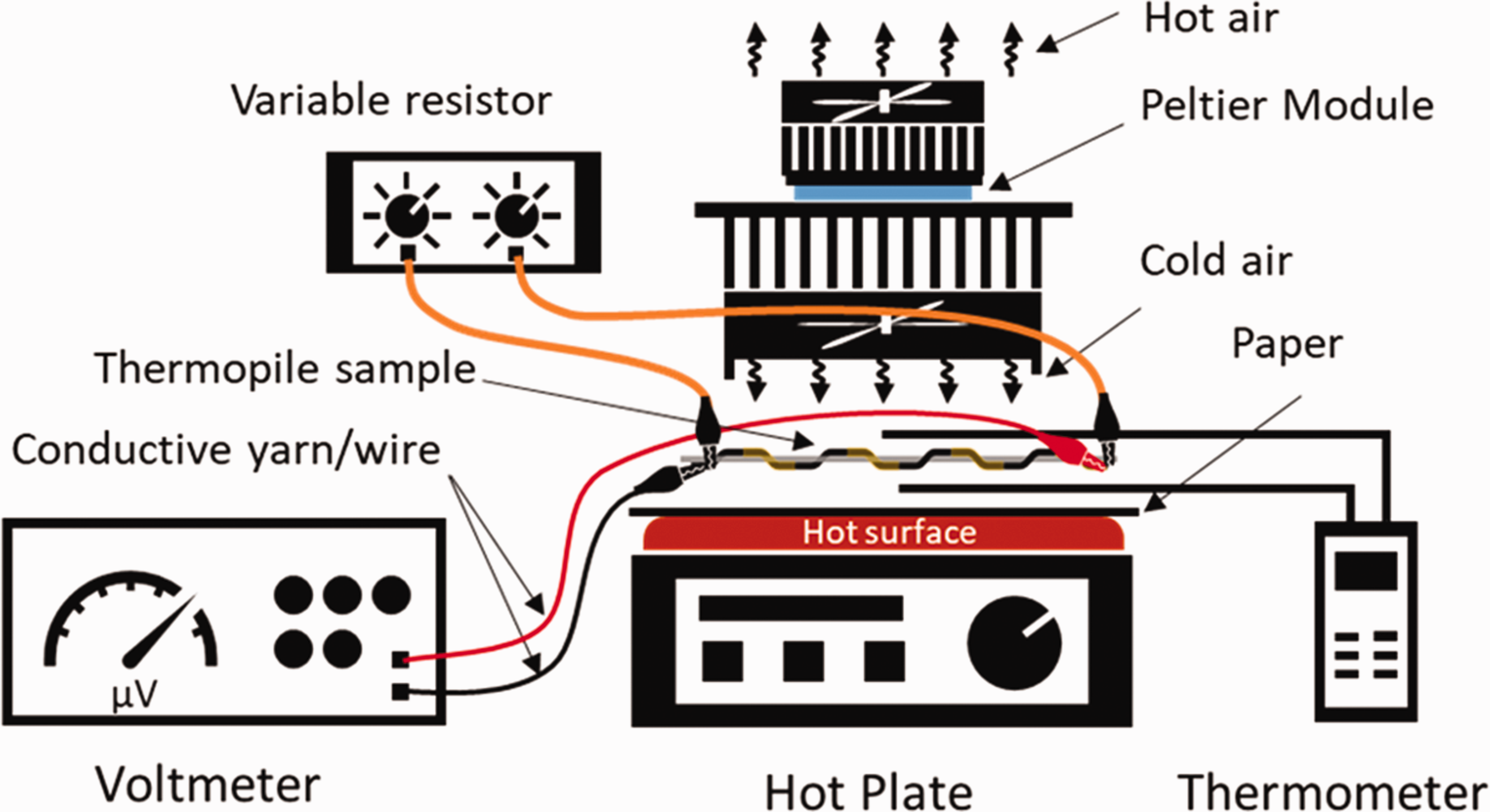
Schematic illustration of the experimental setup of the T-TEG sample shown in black and yellow in the fabric (grey), the paper, and the temperature sensors between a hotplate and a Peltier module.
Result and discussion
In the first experiment trial, we performed the nickel electroplating by connecting the cathode of the power supply directly to both ends of the carbon fiber but the coating result was not uniform along the carbon fiber and the Seebeck coefficient was very low. This is because the nickel coating was mostly taken place on the carbon fiber near to the connected cathode. Therefore, we used two Cu/Ag50 wires inserted underneath the carbon fiber floats located near the two edges of the fabric and connected to the cathode of the power supply as presented in Figure 3. This arrangement helps the nickel plating results to be more evenly distributed along the carbon fiber.
Figure 7 shows the microscope image representation of the carbon fiber float which has been electroplated with nickel. Under the microscope, the polymer (Lurapret® D579) is clearly observed covering a part of the carbon fiber as a shiny transparent coat. The nickel-coated part is also noticed with brown colour next to it.

Optical images showing the nickel and acrylic polymer-coated parts of the C-Ni thermocouples on carbon fibers: (a) topside and (b) bottom side of the fabric.
Figure 8 displays scanning electron micrograph (SEM) images of the untreated CF, acetone-treated CF, and nickel-coated CF as well as the corresponding energy dispersive X-ray (EDS) spectra. The surface of the acetone-treated CF in Figure 8(b) is seen to be a bit cleaner than that of the untreated CF (Figure 8(a)) because the thin layer of epoxy resin has been removed by acetone treatment. However, the EDS spectra of untreated CF and acetone-treated CF look almost identical, but the oxygen peak in acetone-treated CF is detected slightly lower than in the untreated CF as seen in the insets of Figure 8(a) and (b) that could be due to the decreasing of oxygen content from the epoxy resin. The EDS spectrum in Figure 8(c) shows several high peaks of nickel atom on the nickel-coated part of the carbon fiber. It confirms that the nickel is present in a considerable amount on the surface of the carbon fiber.

Scanning Electron Micrograph (SEM) images (left) and the corresponding Energy Dispersive X-ray (EDS) spectra (right): (a) untreated carbon fiber, (b) acetone-treated carbon fiber, and (c) nickel-coated carbon fiber.
The boundary between the nickel-coated area (Ni) and the CF area (or junction in this case) is clearly observed in Figure 9(a) The junction or the boundary line is not seen as a straight line because the application of the Lurapret® D579 was done dropwise by means of a pipette. This causes the irregular shape of the boundary line which depends on the polymer droplet and the wicking action of the Lurapret® D579 dispersion. The wicking action was stopped during the drying and polymerizing process in the oven as the acrylic was polymerized leaving the irregular boundary lines shape.

SEM images of nickel-coated carbon fibers: (a) showing the nickel-coated area and non-coated area and the junction between Ni and CF; (b) and (c) magnification of the nickel-coated area.
Figure 9(b) and (c) shows a greater magnification of SEM images of the nickel-coated CF to see the fibers in more detail. The images confirm that the nickel-coated part of the carbon fiber is fully covered by nickel particles. It is also observed that the nickel particles are sticking to each other covering every single surface of the carbon filaments.
Open circuit voltage was measured by disconnecting the load resistor
To check the Seebeck coefficient of nickel-coated yarn obtained by the electroplating method, a carbon fiber yarn that is the same as the yarn used in the thermopile sample was electroplated separately and afterward paired with carbon fiber. The pair has a coefficient of
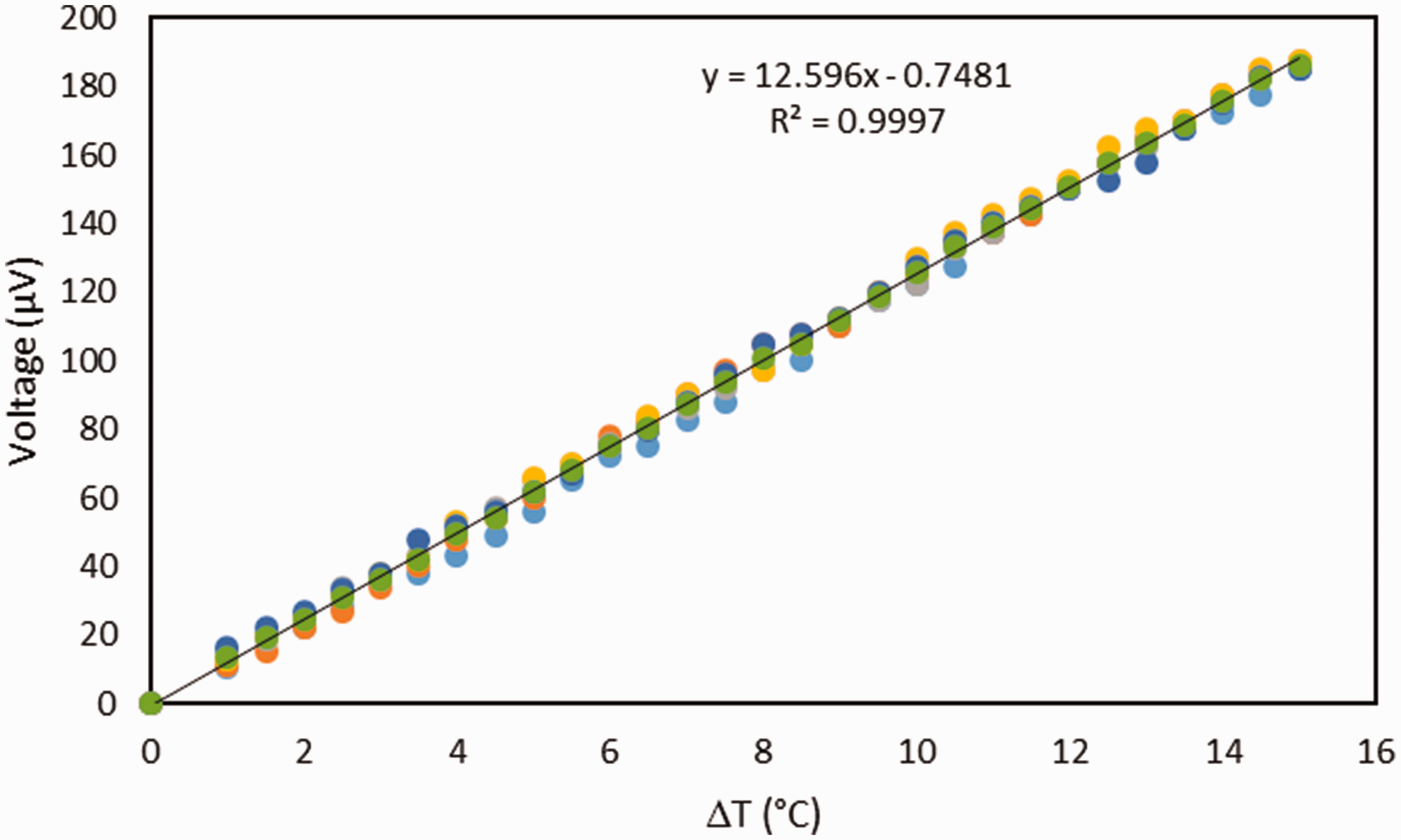
Seebeck coefficient between nickel-coated carbon fiber and untreated carbon fiber. Both fibers have 3000 filaments.
From our previous result [44], the average internal resistance of this T-TEG is found to be
From the circuit diagram in Figure 5, the current supplied to the load 
The voltage 
The power delivered to the load is then found to be
Here,
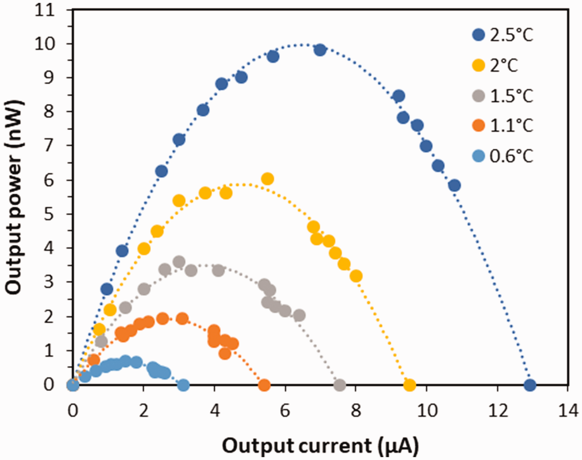
Curve of output power vs. output current of the thermopile sample.
From equation (3), one can find the maximum power 

A plot of the maximum power of the sample is shown in Figure 12. With a 2.5°C temperature different, the thermopile gives a maximum power of almost 10 nW. A quadratic scale for 
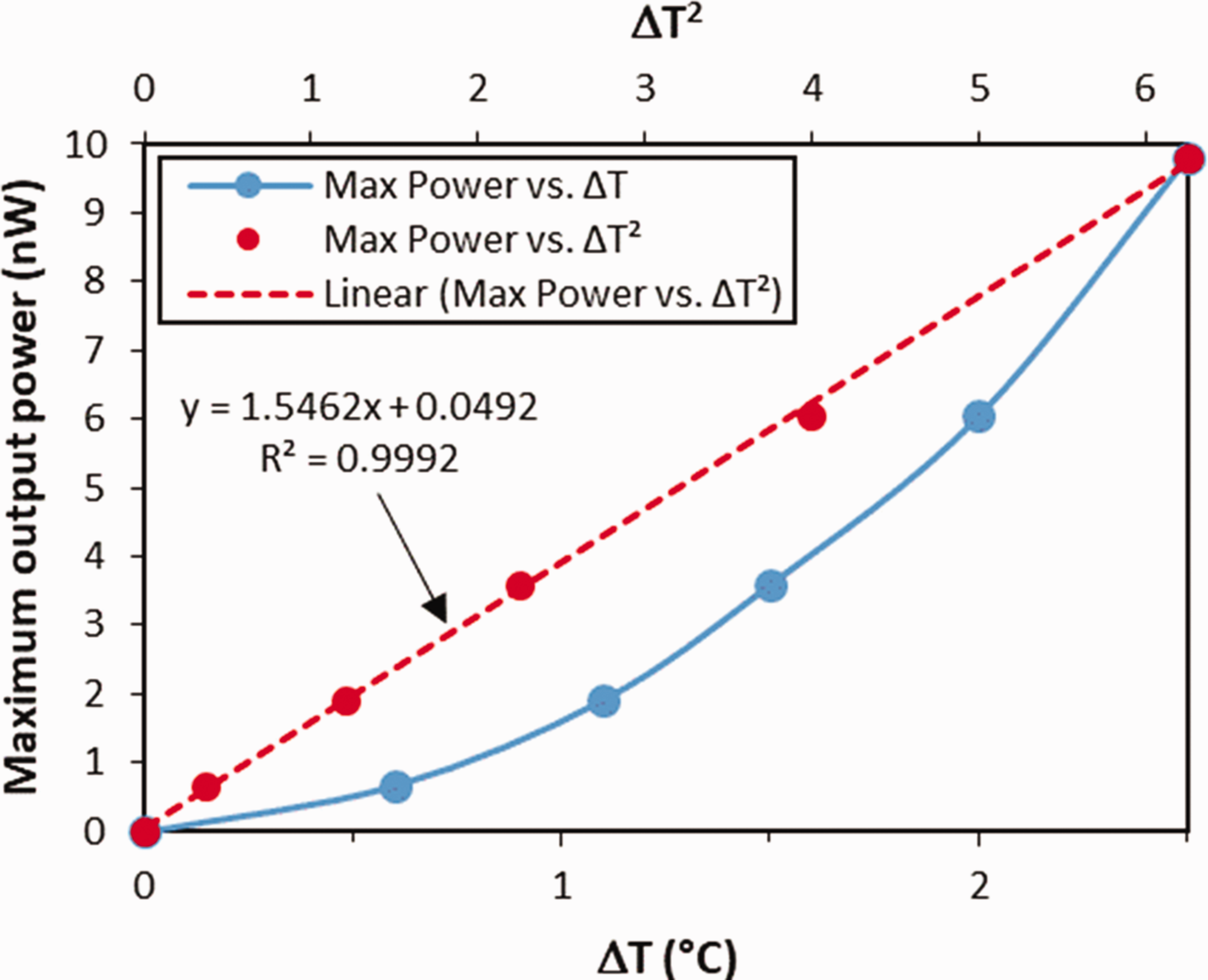
Graph of maximum output power vs. ΔT (solid blue line) as well as vs. ΔT2 (dashed red line).
To convert the unit from nW into watt, 1.5462 is multiplied by 
Using
Conclusion
In conclusion, we have demonstrated the fabrication of a fully T-TEG through electrodeposition deposition process on a tow of carbon fiber stitched on a piece of polyester fabric. Both the substrate and the thermocouples are textile materials. After deposition, it is clearly observed that nickel was deposited on the specific part of the carbon fiber surfaces as confirmed by the SEM images and EDS spectra. There is a series of alternating C-Ni segments on the carbon fiber as a thermopile. The T-TEG consists of 105-pair C-Ni thermocouples. Electrical characteristic measurements have revealed that the T-TEG has a typical characteristic of a thermoelectric generator. This work confirms that it is possible to utilize a conductive textile yarn in fabricating a textile-based thermoelectric generator.
Footnotes
Declaration of conflicting interests
The author(s) declared no potential conflicts of interest with respect to the research, authorship, and/or publication of this article.
Funding
The author(s) disclosed receipt of the following financial support for the research, authorship, and/or publication of this article: Hardianto Hardianto is very grateful to the Indonesian Endowment Fund for Education (LPDP) for supporting this study.