
Abstract
In recent years, the research interest on three-dimensional warp interlock woven fabrics (3DWIFs) as reinforcement in composites is warranted and obtained popularity due to their advantages over two-dimensional laminated fabrics. The current literature tends to address the aspects of mechanical properties of 3DWIFs by experimental and numerical approaches. This review aims at providing an overview and comprehensive understanding of dry 3DWIFs. The filaments/yarns used, the common structures, and categories of 3DWIFs are reviewed. Recent characterizations of the mechanical performance of dry 3DWIFs are discussed. Theoretical and numerical models for predicting the mechanical properties of dry 3DWIFs are also delineated. The critical review can provide valuable ideas and guidance for future studies.
Introduction
In an attempt to overcome many shortcomings with the manufacturing, molding, and application of the two-dimensional (2D) laminates, three-dimensional warp interlock fabrics (3DWIFs) gain tremendous attention as reinforcement in composites over the past decades [1,2]. In addition to the application of the 3DWIFs, they are a new kind of lightweight materials, which are mainly used as composite reinforcements not only in military applications but also widely applied in many others areas such as: navy, automotive, civil infrastructure, wind energy, aircraft, automobile, aerospace, and medical devices [3–10]. These illustrate that 3DWIFs as fibrous reinforcement for composites possessed outstanding mechanical properties and other advantages as compared to the 2D laminates. Various studies have actually revealed that the former is more advantageous than the latter while using the same fibrous material as laminates as fibrous reinforcement for composite materials [11]. The advantages of 3D textile structures in comparison with the 2D ones can be summarized into three main categories: (1) higher resistance to multi-impacts (less damage for an impact) [1,12]; (2) easier and cheaper achievement of structures with complex shapes [12]; (3) superior performance through the thickness [10,13]. However, many researchers address the aspects of the mechanical characterization of dry 3DWIFs scale, which can be evaluated through either experimentation or through a predictive modeling approach. On the contrary, these research work normally focus on certain mechanical properties and at a single scale, in other words, the relative articles only presented one part of the mechanical properties, for example, tensile properties or impact properties, etc. However, there is no overall overview of the main mechanical properties, like tensile, impact, compressive, bending and shear properties, of dry 3DWIFs.
As the mechanical performances of three-dimensional warp interlock composites (3DWICs) depend strongly on the main properties of their reinforcements, in particular, architectures of 3DWIFs, it is necessary to improve the knowledge of the mechanical properties of 3DWIFs. Thus, the present paper aims at providing a global scientific overview of the recent characterization of the mechanical performance of 3DWIFs to get a more profound understanding of the mechanical properties and expand the application of either 3DWIFs or 3D warp interlock composites (3DWICs). With this objective, this review starts with the fiber tows/filaments/yarns structures, and categories of 3DWIFs. Then, the crucial mechanical properties of 3DWIFs are also reviewed. The influences, for instance, geometric parameters and the structures, of the mechanical properties of 3DWIFs are summarized. Finally, theoretical and numerical models currently available for predicting the mechanical strength of 3DWIFs are presented.
A reminder about the 3DWIFs
Fabric architecture plays a significant role in the mechanical performance of fabric and composite laminate [1,2,14–24]. Besides, structure–property correlation is a critical textile research area explored by various researchers, and many factors have been proposed over the years to predict/compare/design the woven fabrics [25]. The structure of a 3DWIF aims at containing not only the woven architecture but also the process parameters as the warp and weft densities, types of warp yarns inside the structure (surface, stuffer, and binding warp yarns), and the number of layers. In addition to the type of fiber and matrix, reinforcing fiber architecture is the main factor which seems to determine the mechanical performance of the reinforced composite [15]. Thus, a better understanding of the 3DIWFs, including the materials, structures, and the classification of source, could be a prerequisite to understand their mechanical properties [16] and design new types of 3D warp interlock structures for different applications [10].
Materials for 3DWIFs weaving
Generally, 3DWIFs compose continuous high-strength multi-filament yarns or tows, which mainly contribute to their performances. For instance, tensile properties are affected by the waviness of the load-bearing fibers and the structural integrity of fibrous preforms is mainly derived from inter-fiber friction [14]. Therefore, it is necessary to have deep knowledge and understanding of the fiber materials for purposes of designing efficient structures.
According to the related literature, the 3DWIFs can be woven in the monolithic or hybrid form using almost any type of fiber tows/filaments/yarns. Although in the earliest reports of the related study, cotton [26] and polyester [27,28] were used for 3DWIFs, the frequently used fiber materials are glass fibers (E-glass and S-glass), aramid fibers (Kevlar and Twaron®), carbon fibers (HexTow® IM7 and Torayca® T700S), and ultra-high molecular weight polyethylene (UHMWPE) fibers (Spectra®). In addition, there are other fiber materials that are rarely used for the 3DWIFs, such as quartz yarn, basalt, and graphite. Recently, it was reported that cellulose-based natural fibers as flax yarns [29] were also used as preform in 3DWICs owing to their environmentally friendly, their recycling properties, and their low-cost prices. The typical properties of commonly used materials reported by several authors are given in Table 1. It can be seen that UHMWPE filaments have the lowest density and approximate Young’s modulus and tensile strength than other high-performance filaments. Furthermore, 3DWIFs, made by UHMWPE filaments, can have lower areal density compared to 3DWIFs made by other high-performance fabrics; thus, they can be applied in the lightweight protection areas. However, using all these high-performance yarns into 3DWIFs has led to some difficulties during the weaving process, especially in the management of warp tensions, compared to more classical yarns as cotton or polyester [30].
The typical properties of commonly used filament material in the dry 3DWIFs studied by researchers.

UHMWPE: ultra-high molecular weight polyethylene.
Structures of 3DWIFs
With respect to the yarn systems of the 3DWIF structure, the researchers hold different views. Ansar et al. [39] regarded 3D interlock woven preforms as multi-layered fabrics produced by interlacing three sets of fiber tows (strands or yarns) in the weaving machine, including warp yarn system that runs in the machine direction (weaving direction), fill or weft yarn system that runs transverse to the machine direction, and binder tows (warp weavers) system interlocked/interlaced the warp and the fill layers. While the other researchers [40,41] stated that 3D interlock woven fabrics structure includes four systems: (1) warp yarn (tow/strand) system located at the top/bottom surface, (2) weft (filler) yarn system is perpendicular to the warp yarns and inserted at each shed motion by different insertion system of the weaving loom, (3) inserting (stuffer warp/longitudinal) yarn system is also selected by the heddles of the weaving loom and is conducive to the longitudinal mechanical properties of the multi-layer fabric, and (4) binding warp (weaver or web) yarn system is selected by the heddles of the weaving loom and allow to link in the thickness the various layers of the fabric, as shown in Figure 1. Therefore, the main differences between them are that the yarns at the top/bottom surface (as called surface weaver) are integrated into the woven structure when it requires a specific aspect on the surface of each side of the fabric with a more or less precise roughness [41].

Schematic representation of a cross-section of the weft yarns of the 3DWIF structure [41].
Actually, the presence of binder warp yarns, which play a vital role in determining the mechanical properties of fabrics, can improve the structural integrity and achieve high out-of-plane mechanical properties [19,42]. This suggests that the weaving of the binder has opposite effects depending on its woven orientation with respect to the loading direction: it weakens the material by crimping weft tows and strengthens the warp direction by becoming an additional load-bearing component without crimping them, resulting in the warp direction being stronger as shown in recent studies [43,44].
It is also significant that both warp binder path (X) and binding depth (Y) have a certain impact on the mechanical properties of 3DIWFs. Figure 2 shows the cross-section of the weft and 3D views of the geometrical representation of a 3DWIF sample, based on the binding step and depth, number of layers, and warp binder path. Specifically, warp binder path influences properties both in the warp and weft directions, and the binding depth of interlocking warp plays an important role in determining the efficiency of the reinforcement in the loading direction [45]. There is no doubt that binders are helpful to improve the mechanical behavior of the 3D composite [46], for instance, the delamination toughness [15,17,47–49], impact damage resistance and post-impact mechanical properties, and tensile strain-to-failure values [47]. For the purpose of the good properties mentioned above, these can be achieved by controlling the number of z yarns, with a low-volume content of z-binders [50] and usually less than 5% [47].

Representation sample of 3DWIF architectures based on the binding step and depth and number of layers, warp binder path (X = 2) and binding depth (Y = 2).
Classification of 3D woven fabrics
It is certain that the 3DWIFs belong to the branch of 3D woven fabrics class [39]. Good understanding of 3DWIFs classification can contribute to the study of its structure and performance. In general, 3D woven fabrics have been divided into several types according to different classification methods, as shown in Table 2. The main classification method is based on the weaving process, yarn interlocking mechanism, and manufacturing methods. However, there is no unification in classification. A 3D woven fabric can be completely specified by different parameters including the type of fiber used, number of layers of weft and warp yarns, binding type, number of filaments in a warp and weft yarn, warp and weft yarn density, fabric areal density, fabric thickness [2], etc. The 3D woven preforms are classified, which is an arduous task because of the different criteria [51], based on various parameters such as fiber type and formation, fiber orientation and interlacements, and micro- and macro-unit cells [52].
Classifications of major types of 3D woven fabrics.
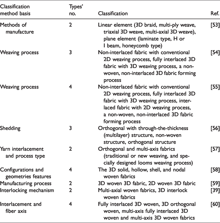
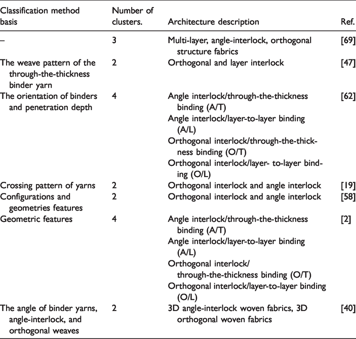
As for 3DWIFs which have been widely investigated in the past few years with the results of a variety of structures, Umair et al. [61] divided the 3D interlock woven fabrics into two types: warp and weft interlocks, based on the fact that the dedicated binding yarn can link the layers (either warp or weft). It is not easy, indeed, to understand the variety of 3DWIFs due to the wide variety of fiber architectures [12] which can be produced with controlled amounts of binder yarns for the through-thickness reinforcement [47] and the classification criteria which can be different [2,40], as shown in Table 3. Ding [62] and Chu et al. [2] use the same classification, and Gu and Zhili [19] and Chen [58] have added the geometric features. In fact, the former classification gives more details compared with the latter classification. On the basis of the interlocking mechanism which considered the weave pattern of interlock with binding yarns in fabric thickness, the 3DWIFs are commonly categorized into two main types [6,47]: 3D angle interlock woven fabrics and 3D orthogonal interlock woven fabrics, and each type involves the through-the-thickness and layer-to-layer binding. If the penetration depth of binders is concerned, each type can be divided into two kinds: layer-to-layer fabrics and through-the-thickness fabrics [2,39]. Due to the complex structure of 3DWIFs, it creates some confusion among various researchers, scientists, and weaving technologists. Considering such problems, some researchers have studied dedicatedly on detailed descriptions, components, and general design specification of 3D warp interlock fabrics for better clarification and understanding [41]. There are four main categories of 3DWIFs, as shown in Table 4 with examples.
Classification types of 3DWIFs.
Examples of four main categories of 3DWIFs.

A/T: angle interlock/through-the-thickness binding; A/L: angle interlock/layer-to-layer binding; O/T: orthogonal interlock/through-the-thickness binding; O/L: orthogonal interlock/layer-to-layer binding.
Other research study has highlighted the achievement of 3D weft interlock fabric, produced on a specific shuttle weaving loom equipped with Jacquard warp selection, which also revealed the higher crimp of weft yarns compared to strictly high straight warp yarns, mainly due to a very applied tensile load on warp yarns and poor tensile load on weft yarns [63].
There are also differences in the performance of two types of 3DWIFs. By the way of comparison, 3D warp orthogonal-interlock fabric (3DWOIF) can provide better fiber volume fraction especially in the thickness direction [39] and larger surface damage area [64], while the 3D warp angle-interlock fabric (3DWAIF) can greatly increase folding ability, distortion capability [39], the structural stability, and resist to delamination [6]. It also provides relative good through-the-thickness mechanical properties [65], which is mainly owing to the weft yarns that are interlaced through the different layers of the warp yarns in the fabric architecture [66]. By contrast, 3DWAIFs have low shear rigidity compared to woven fabrics with other structures [28]. In particular, non-crimp 3D orthogonal woven preform 3WEAVE® composites, having practically straight in-plane fibers, show significantly better in-plane stiffness and strength properties than respective properties of conventional type 3DWICs [43]. When comparing the layer-to-layer binding with the through-the-thickness binding, the latter provides a greater volume of fibers in the fabric; however, orthogonal interlock/through-the-thickness binding (O/T) fabric is less flexible than the angle interlock/layer-to-layer binding (A/L) fabric [67,68].
In conclusion, the definition of a systematic classification method of 3DWIFs is helpful for the comparison of the performances of different structure fabrics and is also conducive to the design of new structures. Moreover, the pros and cons of the performance of these materials can also be considered to select the right structures for different application fields.
Mechanical characterizations of 3DIWFs
In order to characterize and obtain relevant data to optimize the applications of 3DIWFs and their reinforced composites, the experimental approaches are commonly used methods to investigate the mechanical performance of 3DIWFs. It is essential to characterize the mechanical properties when considering the composite reinforcements. Great efforts have been made to characterize the mechanical properties of 3DIWFs. The mechanical performance of 3DIWFs may be influenced by several factors: the reinforced fibers (Para-aramid, Carbon, E-glass, etc.), the type of yarns (single yarn, plied yarn, filaments, etc.), the architectures (angle-interlock, orthogonal-interlock, etc.).
Considering the research works done on their mechanical characterizations, several main properties of 3D warp interlock fabrics as tensile, impact, compressive, shear and other have been revealed.
Tensile properties
Despite the fact that tensile behavior is the basic property for designing the 3DWIF products, there is less research with regard to the tensile fracture mechanism in literature. Uniaxial tensile tests or unidirectional tensile tests have been done to evaluate the tensile behavior of 3DWIFs, while these tests rarely highlight biaxial tensile tests, and all of them are the quasi-static uniaxial tensile tests. All these tests have been performed considering the following standards as: ASTM D5035 [1], NF ISO 4606 [45], ASTM D3039 [48], and EN ISO 13934-1 [70]. With respect to the existing experimental apparatus, different types of tensile machines were frequently used. However, Hou et al. [7] tested by using self-designed split Hopkinson tension bar (SHTB) apparatus which has become a standard machine to perform tensile tests at low to medium and high strain rates currently, while there is no clear standard procedure for the high-strain rate tensile tests by SHTB.
Table 5 gives a conclusion about the tensile test results relative to 3DWIFs. In the previous study, the researchers paid more attention to the effect of the weaving parameters [26,70,72,73] of the 3DWIFs tensile properties. Chen and Zanini [26] studied the influence of the binding weave and the number of layers on the tensile properties of different binding weaves of3D orthogonal interlock fabrics. It is understandable that the binding weave does not contribute significantly to the tensile stiffness, to the strength, or to the elongation. This may be explained by the configuration of the orthogonal structures. Boussu et al. [70] compared the tensile properties of four different types of 3DWIFs (A/L, orthogonal interlock/layer-to-layer binding (O/L), O/T, angle interlock/through-the-thickness binding (A/T)) in warp and weft directions, respectively. It was pointed that 3D A/T interlock fabrics had the two peaks in the force-elongation curve of warp direction, which was similar to Bandaru et al. [1] presented for 3D-A fabrics. In fact, the first peak indicates the strength of the warp yarn and the second peak indicates the strength of the binder warp yarn where the second part of warp yarns can work after the break of the first yarns, as shown in Figure 3. While for the test in the weft direction, the influence of the binding appears less sensible than in the warp direction, but most of the mechanical properties depend on the resulted geometry given by the 3D warp interlock fabric architecture. It was also demonstrated by Bandaru et al. [1] that the strength and failure strain in the weft direction was greater than the warp direction, also taking three different materials into account, which means that, in the warp direction, stuffer warp yarns were straight and binder warp yarns were orientated at an angle, while all the yarns were parallel and straight in the weft direction. However, as a matter of fact, no matter the yarns in the warp direction or the weft direction, all the yarns were not straight inside the fabrics.
Tensile properties of 3DIWFs.

A/T: angle interlock/through-the-thickness binding; A/L: angle interlock/layer-to-layer binding; O/T: orthogonal interlock/through-the-thickness binding; O/L: orthogonal interlock/layer-to-layer binding.
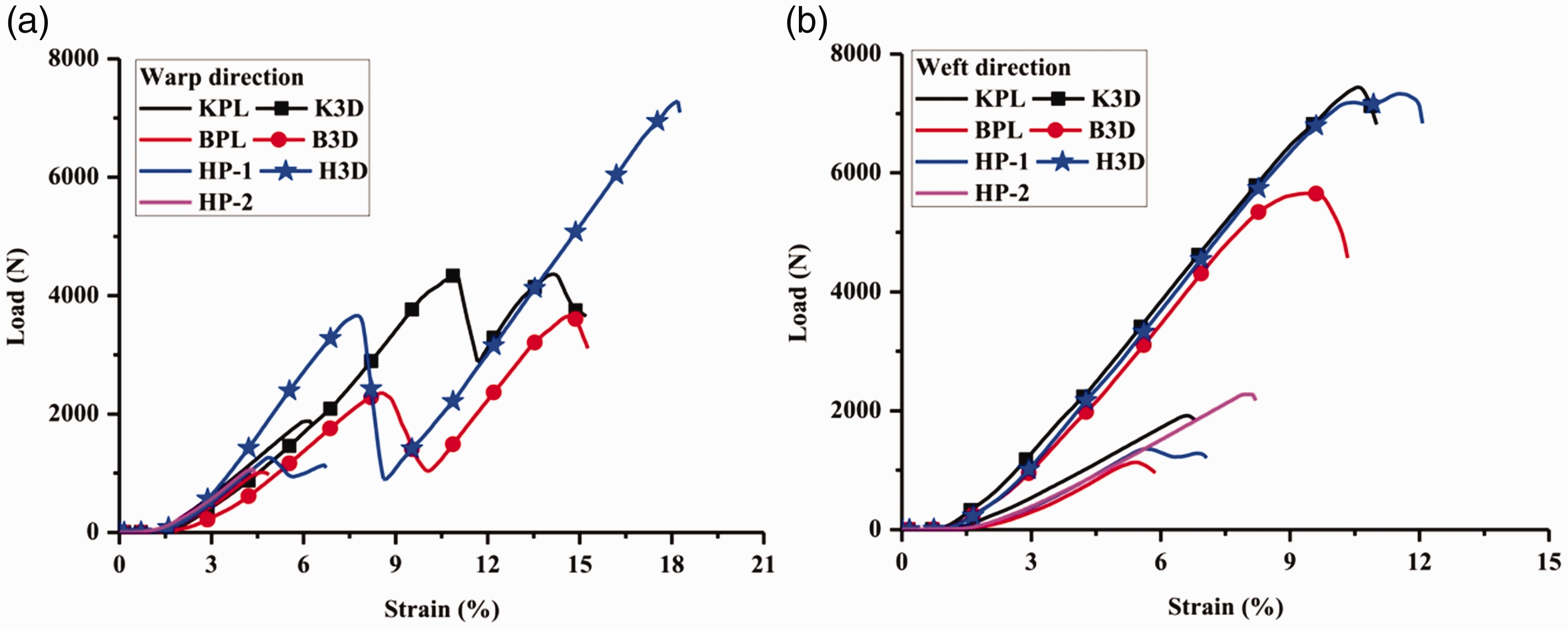
Comparison of the tensile response of 2D-P and 3D-A fabrics [1]: (a) warp and (b) weft.
Furthermore, the effects of the type of yarns on tensile properties were studied by Bandaru et al. [1] and Corbin et al. [29]. In the case of 3D-A fabrics, the failure strain was different in both the warp and weft directions. Although the strength of Kevlar 3D fabrics was superior to the Basalt 3D fabrics, the hybrid combination of basalt and Kevlar yarns (H3D) improved the failure strain by 6.53–36.71% and 4.46–23.31% in both the warp and weft directions, respectively. Although the areal density of Basalt 3D fabrics was higher, these fabrics exhibited lower failure strain due to the brittle failure of basalt yarns in the loading direction. An alternative way (i.e. intra-layer hybridization at the fabric level) was suggested to improve the mechanical performance of the fabrics under static and dynamic loadings with reduced areal density. It was presented [29] that the similar behavior in the weft direction for the two architectures and mainly for the para-aramid and E-glass yarns reveals a lack of influence of the 3D woven structure onto the weft yarns.
Influence of fabric architecture on tensile properties was also explored by Dash and Behera [71] and Bandaru et al. [1]. The former resulted that higher strength, in comparison to other structures, is obvious due to the role of coarser binder tows that were used during weaving for these structures. The latter gave a comparison of the typical load–strain response of two-dimensional plain woven (2D-P) and 3D-A fabrics in the warp and weft directions (as shown in Figure 3). The crimp region of both 2D-P and 3D-A fabrics was approximately close. The better tensile response of 3D-A fabrics was due to the presence of binder yarn and more number of yarns/inch in the warp and weft directions than the 2D-P fabrics. The increase in strength and failure strain of 3D-A fabrics was due to the addition of binder yarns in the thickness direction, which improved the strength and in-plane stiffness of the fabrics [74,75]. Therefore, the binder yarns are beneficial to the tensile properties of 3DWIFs because they can hold the warp and weft yarns together in the thickness direction improving the in-plane stiffness and strength of the fabrics [13].
As initially investigated, Hou et al. [7] have achieved experimental testing and theoretical modeling regarding the tensile behavior of the 3D angle-interlock woven (3D-A) fabric under high strain rates. Before this study, high-strain rate tensile tests about woven fabrics only confined to 2D woven fabric structures, especially on plain woven fabric, have been reported in several literature [76–78]. From Figure 4, it could be found that the tensile fracture mechanism of the 3D-A fabric under quasi-static loading was different from that under high-speed condition. When the specimen was stretched under quasi-static loading, the whole fabric has sufficient time to be in a uniform stress state. But when the 3D-A fabric was subjected to a high-strain rate load, there was no time for the stress wave spreads to the entire structure before some fiber tows fractured. The principal reason for such a difference could be attributed to the stress wave propagation in this unique architecture. Furthermore, a two-phase tensile stiffness phenomenon was observed from the stress–strain curve under high strain rate. The first stress peak value was much smaller than the second one and the elastic modulus decreased during the two stages. It could be found that the reasons for the strain rate sensitivity come from the non-simultaneous fracture of the fiber tows in the different layers and the stress wave reflection at the cross-points of the warp fiber tows and the weft fiber tows. In a word, tensile behavior of other types of 3DWIFs, like O/T or O/L, has not been explored under high strain rates which might extend the application of 3DWIFs in special conditions.

Tensile stress–strain curves of 3DWIF under different strain rates [7].
Impact properties
In short, an impact with the same energy may happen with two distinct situations: low-velocity impact (LVI) by a large mass (drop weight) and high-velocity impact (HVI) by a small mass (debris, bullet, etc.). The former is generally simulated using a falling weight or a swinging pendulum and the latter using a gas gun or some other ballistic launcher [79–81]. The energy loss of the projectile is an effective way to measure the fabric’s capability of absorbing energy which is difficult to measure directly [81]. Impact on a woven textile panel is different from the equivalent impact on a single fiber due to the complex interaction at fiber crossover points [82]. In comparison, many researchers give more importance to the HVI properties rather than the LVI properties, as shown in Table 6. Table 6 gives the results of the 3DWIFs which differed in terms of architecture, materials, energy level used related to the impact properties.
Impact properties of 3DIWFs.

LVI: low-velocity Impact; HVI: high-velocity impact; FSP: fragment simulating projectile.
Low-velocity impact
Taking into consideration the final application of the composites, fabrics were tested to know their impact properties. CEAST9350 impact tester was used for the LVI impact property according to ASTM D3763 standard, as shown in Table 6. It is established that 3D fabrics exhibit better impact resistance properties in terms of total energy, peak absorbed energy, and peak resistance when compared with an equivalent areal density of 2D fabrics [1,83]. This is due to the increased structural integrity of fabrics that improve the in-plane stiffness, damage tolerance, and energy absorption and fracture toughness. That is to say, the yarns in the thickness direction of 3D fabrics play a vital role in holding all the weft and warp yarns together.
The influence of hybridization and fabric architecture on the LVI response was studied by Bandaru et al. [1]. Due to the lower areal density of Kevlar 2D-P (KPL) among 2D-P fabrics and Kevlar 3D-A (K3D) among 3D-A fabrics, these fabrics exhibited poor LVI performance. However, due to the hybridization, the LVI of fabrics performance of these fabrics was enhanced by 41.28–42.73% and 36.89–37.71% for 2D-P fabrics in terms of peak force and energy absorption, respectively. Similarly, 14.70–41.44% and 13.45–20.14% improvement in the peak force and energy absorption of 3D-A fabrics was observed, respectively, due to hybridization.
It is clear to see that in Figure 5, which shows the typical force–time response of different 2D-P and 3D-A fabrics. These curves provide a thorough representation of failure initiation, propagation, and degradation of the fabric stiffness. In the initial stage, the force–time curves showed a constant branch for all the fabric samples, which was probably due to the flexibility of the fabrics. In the second stage, as the impactor penetrated into the fabric, it stretched the fabric and formed a local indent as the contact force increases. The change of slope in the curve indicates the initiation of damage in the fabrics. After initial failure, few fluctuations in the curve represent the separation of yarns with failure, resulting in the stiffness degradation of fabrics. The peak force in the curve represents the maximum load that a fabric could withstand before undergoing critical damage. The force decreased after reaching the peak value and there was a redistribution of the load of the surviving fabrics until the impact load was removed. A sudden decrease in the force after the peak force indicates the complete failure of the fabrics. More load oscillations were observed in the case of basalt fabrics as compared to the Kevlar and hybrid fabrics.

Force versus time response of different fabrics [1]: (a) 2D-P and (b) 3D-A.
Moreover, in order to determine the role of different weaves on impact energy, a normalized value is worked out by Abtew et al. [72] with respect to fabric areal density, as shown in equation (1)
From the discussion of Dash and Behera [71], it is the total number of crossover points determined by tow-to-tow interlacement patterns leading to more compactness which in turn are responsible for more impact energy absorption.
High-velocity impact
Woven fabric has been used for constructing soft body armour in the last few decades [87,88]. In general, the ballistic impact is the most common test in HVI characterization. Ballistic protection can be classified into two types: the soft protection, which is mainly dedicated to the body armour to protect humans (civilians and soldiers), and hard protection, which is used for protection of mobile platforms [84]. Enhancing soft body armour performance constructed from 3DWIFs requires a full understanding of the ballistic impact response and wave propagation during the ballistic impact process.
Several papers [81,85,86] have described the impact behavior of 3DWIFs and have been compared to existing 2D laminates, as summarized in Table 6. Three-dimensional fabrics woven are more resistant to impact when compared to the 2D fabric due to the availability of unique energy dissipating mechanisms introduced by the presence of reinforcement along the Z plane (Z tows) [85,86]. It also shows high performance in ballistic protection with high flexibility and lightweight [85] over 2D woven structures [84]. While Yang et al. [81] showed that 3D-A fabric demonstrates relatively low capabilities of absorbing the impact energy, compared to fabrics of other structures. This is mainly determined by angle-interlock woven fabric structure, which consists of layers of weft yarns laid straight and bound by a single layer of warp yarns to lock the layers of weft yarns together. This unique structure leads to less interlacement which, however, limits the stress wave propagation in the fabric during the HVI.
Additionally, Lefebvre and Boussu [84] presented ballistic tests on a few samples of 3DWIFs. Variation of energy absorption versus the number of layers is analyzed in their paper. It concluded that similar warp and weft densities have better energy absorption behavior. Besides, it is better to use aramid fiber instead of PE fiber for the same soft ballistic protection, even though PE fibers have better mechanical properties than aramid. Jia et al. [89] performed similar tests to measure ballistic limits of a type of 3D woven fabrics. From the above review of previous studies, it is clear that few works have been focused on the role of impact localization on the ballistic performance of dry 3DWIFs [2]. Moreover, Ha-Minh et al. [12] carried out ballistic tests on impact behavior of a 3DWIFs of four layers in two cases: perforation (400 ms−1) and non-perforation (306 ms−1), which is also unprecedented in the research area, as shown in Figure 6. Formation of a deformation pyramid is the unique mechanism observed between 0 and 120 µs. We observe that the pyramid top of three results almost has the same distance from the plane of fabric (Figure 6(a)). The size of the deformation pyramid in the warp direction is greater for this case. The reason is that the projectile has more time to penetrate the fabric (Figure 6(b)). This paper has also indicated that the complex geometry of 3D woven fabrics due to the weaving process is extremely difficult to take into account. Besides, there is no clear trend between the thickness of the structure and the trauma depth, and more information data from the further investigation are required to establish a conclusive relationship [85]. Increasing thickness of the angle-interlock fabrics seems to influence trauma depth, with the same warp and weft densities under the same standard and higher areal density does not indicate better ballistic performance [85].

Comparison of the impact case of non-perforation (306 ms−1) (A) and perforation (400 ms−1) (B) with a side view between: (a) experiment, (b) model using dynamic properties, (c) model using static properties [12].
Some relatively unique and original research methods were adopted to study the ballistic properties of 3DWIFs, for example, scanning/contrast imaging and X-ray tomographic techniques [86]. A specific experimental apparatus has been designed in order to completely avoid slipping problems at clamps of yarns using steel cylindrical bars inserted just during the weaving process, and fragment simulating projectile (FSP) is used for impacts [12]. Furthermore, Chevalier et al. [90] revealed that similar warp and weft densities have been beneficial to a better energy absorption behavior, which is the result of a wider orthotropic distribution of mechanical stresses and strains during the impact. Additionally, it has been observed that a linear behavior of 3DWIFs with the number of plies is involved in the different tested samples after a high value of impact velocity.
With respect to the energy absorption mechanism when the projectile hits the woven fabric, normally for 2D woven fabrics, Cork and Foster [91] and Wang et al. [92] pointed out that two waves take place: longitudinal and transverse strain waves. Figure 7 depicts the propagation of the two waves. On the one hand, the longitudinal wave travels in the plane of the target plate. This wave travels through the yarns which are directly hit by the projectile, known as primary yarns. The yarns not directly hit by the projectile are known as secondary yarns, which also travel through this wave because they interact with the primary yarns [93,94]. On the other hand, the transverse wave propagates outwards from the impact zone to make deformation in the perpendicular direction to the fabric plane. The fabric deformation due to the transverse wave is shaped like a cone with the impact point at its vertex [91,95]. Projectile creates a transverse deflection in the primary yarns, whereas longitudinal stress waves also propagate away from the impact point along the axes of principal yarns at the sound’s speed during impact tests. However, the number of warp/weft yarns hit by the projectile makes the fabric energy absorption process very complicated. This is due to the fact that the projectile may hit on yarns, interlacements, or on the gap between yarns. When the projectile hits only few yarns on the impacted area, the results will be very complicated. A more detailed overview of ballistic impact mechanisms of textile materials is reviewed by Abtew et al. [96].

Zones of primary and secondary yarns in a fabric subjected to impact: (a) face view and (b) side view [97].
The failure mechanism of 3D interlock woven fabrics and effects of boundary conditions and friction have been investigated by Chu et al. [2] using numerical modeling which is validated by experimental tests. Fabric specimens are impacted by a projectile with a velocity of 306 m/s at two different shooting positions: fabric center (FC) and fabric quart center (FQC), which means that the fabric specimen that is used for the FC shooting has been reused for the second FQC test. As seen in Figure 8, after two shooting tests (FC and FQC) at a velocity of 306 m/s, the results showed that the fabric was not perforated in the FC shooting test (Figure 8(b) and (c)). On the other hand, it was clearly perforated in the FQC shooting test (Figure 8(d) and (e)). It can be noted from the back views that weft yarns, that are under the projectile (primary weft yarns), were pulled out at the impact point (Figure 8(c) and (e)), while it was not clear for the primary warp yarns. This is due to that the warp yarns are being clamped down, while the weft yarns are not. In the FQC test, the yarn-pulling-out occurred mainly on the side near the free edge (Figure 8(e)). Considering the front view at the impact point (Figure 8(b) and (d)), the primary yarns (both weft and warp) in the front face of the fabric are cut by the sharp projectile edges. During impact, the global localization affects the deformation of the whole fabric through the primary weft yarn pulled-out mainly on the side near the free edge of the fabric, while the impact location decides the failure mechanism of primary weft and warp yarns around impact location.

Fabric specimen after the experimental impact test: (a) overview – back face and close-up views at impact point: (b) FC shooting – front face; (c) FC shooting – back face; (d) FQC shooting – front face; (e) FQC shooting – back face [2].
In addition, Ha-Minh et al. [98] analysed damage mechanisms of 3D interlock woven fabric subjected to ballistic impact using a numerical model. The failure mechanism of 3D interlock woven fabrics and effects of boundary conditions and friction have been investigated by using numerical modeling which is validated by experimental tests. The damage mechanisms of the 3D fabric have been investigated in two corresponding impact cases: no-perforation and perforation. Indeed, when the projectile does not penetrate through the target, the propagation and reflections of strain waves exist during the whole impact event. When the projectile penetrates through the target, strain waves propagate far as fabric edges. It is noted that strain waves go in the weft direction more rapidly than the warp direction. This due to that the yarn undulation in the weft direction is lower than in the warp direction. Besides, the effect of boundary conditions on fabric damage zones also indicates that they significantly influence damage mechanisms and ballistic performance of the 3D fabric.
In general, these results are not enough to characterize ballistic behavior of 3D woven fabrics, because failure mechanisms during impact are not studied enough. More tests should be done to extend the results with other bullet impacts.
Compressive properties/compressibility
Understanding the compaction behavior of composite textile fabrics is of great industrial relevance. Since 3DWICs can be manufactured using liquid composite molding (LCM) processes where dry reinforcement fabrics are placed in a mold and subsequently injected with resin. During the LCM process, the compaction of textile reinforcement is an important aspect [99]. These processes involve compaction of the reinforcement at different steps of fabrication. Compressive tests done on soft 3DWIFs could also help to determine the force required to compact a fabric at a certain thickness or the limit of the fiber volume fraction without severe degradation of fibers. For these reasons, it is important to understand how the architecture and the processing parameters affect the compaction behavior.
However, previous studies mainly focused on traditional 2D woven fabrics. Numerous experiments and theoretical investigations have studied stacks of 2D fibrous laminates, in which a random phenomenon called nesting plays a significant role [100–102]. Usually, in a 2D fabric, the compaction of fiber reinforcement begins with a gap reduction between the weft and warp tows, and once the inter-tow gap reduces, the tows start to flatten and nest with adjacent tows.
As shown in Figure 9, 3D woven preforms also exhibit a degree of yarn waviness (curvature) that decreases with the application of external pressure. The compression behavior of fibrous reinforcements [99] was governed by two main phenomena, namely tow flattening and bending. First, tow flattening takes place at the level of the filaments contained in the fiber tows, which are squeezed and change the shape under the effect of the compression force. Second, towed bending occurs at the level of the fabric structure. There are more details about the transverse compaction of single yarn [109]. The compaction force necessary to obtain a given fiber volume fraction depends not only on the architecture of the fibrous reinforcement but also on processing parameters, such as the compaction speed and lubrication [110]. Vernet and Trochu [99] considered that compaction behavior is mainly governed by tow flattening and bending and have developed a model to estimate the total compaction force of fabric depending on weaving parameters. In a review of the work by previous authors, a number of factors have been identified which affect the compressive qualities of a woven textile [105]: binder density – the number of through-the-thickness tows per unit area, initial fabric thickness, and reorganization of the fabric structure.

(a) Change in tow-waviness and (b) flattening of tow due to external pressure [111].
As far as it goes, there are few published studies on the compaction characterization of dry 3DWIFs [21,104,105]. Analysis and modeling of the compaction behavior of 3D woven fabrics have also been recently done [111,112], but not as widely as for 2D fabrics. The compaction behavior of 3D carbon interlock fabrics was mostly explored (as shown in Table 7). It can be concluded that 3D orthogonal interlock fabrics have the greatest compaction resistance in comparison with another type of 3DWIFs. Potluri and Sagar [111] studied the compression response of different 3D weaving patterns and validated a model based on an energy-minimization technique using their experimental data. Charmetant et al. [113] analyzed experimentally and numerically the transverse compression of the 3D layer-to-layer angle interlock composite reinforcements. Endruweit [104] concluded that different fabric architectures had different compression mechanisms during LCM processing. The compression behavior depends strongly on the fabric architecture. For an angle interlock weave at high compression levels, the main mechanism is the change in bundle cross-section. In contrast, the main controlling mechanism in an orthogonal fabric is the compaction behavior of the through-thickness Z-fiber bundles. For an orthogonal weave, the main compression mechanism is a compaction of the fiber bundles. The compressibility is similar to that of UD layers. In cyclic compression, the compressibility of the angle-interlock weave is reduced after the first cycle, because of permanent reordering of the fiber bundles in the fabric structure, and remains approximately constant in subsequent compression cycles. For the orthogonal weave, the effect of reordering and the reduction in compressibility is less significant.
Compressive properties of 3DIWFs.

More recent work on yarn compression has been done by Renaud et al. [103]. They studied the creep compaction behavior of 3D carbon interlock fabrics for various temperature and lubrication cases, which enhance an already large knowledge on composite fabric’s compaction behavior. Fabrics A, B, and C had different weaving parameters (pattern, warp/weft ratio, and number of fibers per tow). As presented in Figure 10, it appears that increasing the flattening ratio allowed to increase

Creep compaction curves of dry fabrics B and C tested at 25°C and 160°C (a), impact of flattening ratio on
Alhussein et al. [106] found that orthogonal fabrics were harder to compact to a fiber volume fraction of 0.65, requiring 2.3 MPa compression stress. The material with least stiff was the layer-to-layer structure due to the fact that the z fibers in the layer-to-layer structure were less vertical, thus stiffening the structure less in the z-direction. The orthogonal material has tows that run vertically downwards through the stack, and this material generated the highest compaction response. In addition, they explored the single-cycle compaction and multiple cycle compactions. The results of the cyclic tests qualitatively reflect the single compaction tests, where the orthogonal preforms require higher loads to compact to the final Vf. As the loading and unloading cycles progress, the reinforcements reach a point at which there is no significant difference in peak stresses and the cycles become repeatable.
Umer et al. [107] compared the compaction response differences of orthogonal, angle interlock, and layer-to-layer interlock fabrics. It can be very clear that the stress drops instantaneously and continues to relax until there is no further evident drop after reaching the peak value, as shown in Figure 11. Due to reduced nesting effects between the tows, the mesoscopic spaces remained opened in the fabric during compaction, before mold filling. The orthogonal fabrics were found to be stiff due to the tightly woven patterns of the vertical z-binder yarns. In the orthogonal and angle interlock fabrics, the tows did not expand freely due to the presence of the vertical z-binder yarns, hence higher compaction loads were required. As a result, in an actual LCM process such as RTM, the orthogonal and angle interlock fabrics will require high tooling forces or will compact to a lower fiber volume content under 1 atm (100 kPa) vacuum pressure, such as with VARTM.
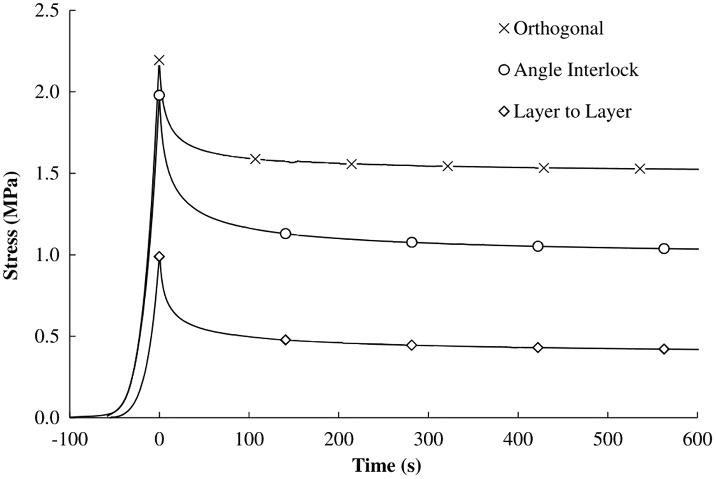
Dry compaction response of 3D fabrics [107].
Bending properties
Many experimental works have been carried out to measure the flexure of fibrous materials. Bending behavior is a specific complex multi-scale mechanical problem which can be investigated through three main test families reviewed by Boisse et al. [114,115] are respectively as follows: cantilever bending, Kawabata test (imposed curvature), and three-point bending. In the present study, numerous experimental studies have been reported on the on-axis bending behaviors of 3DWICs. For example, Jin et al. [116] have presented the quantitative characterization of cumulative fatigue damage behavior for the three-dimensional angle-interlock (3D-A) woven composite undergoing three-point bending cyclic loading. Zhang et al. [117] have demonstrated the influence of the off-axis angles on the flexure behaviors of 3D woven carbon/epoxy composites. However, little research work was addressed to the bending properties of dry 3DWIFs.
In Table 8, these tests mainly study the influence of the bending weave, the number of layers and fabric densities. Chen and Zanini [26] studied the influence of bending weave and the number of layers. They pointed that the type of binding weave affects the bending stiffness with a great deal, which is especially true for the structures thicker than two layers of straight warps. Hence, if a composite reinforcement requires higher bending stiffness, plain weave should be used to bind the orthogonal structure. Second, an increase in the number of layers is an effective way of obtaining higher bending stiffness and bending hysteresis. Abtew et al. [72] revealed that regardless of fabric density, yarn density in the specific direction plays a great role in the values of bending length. The result does also support the previous study observations [118]. 3DWIFs show a similar trend with the 2D fabrics [119], with higher fabric areal density, and bring better values than that of samples with low areal density. This is due to the fact that as yarn density increases, the frictional and geometrical restraints within and between yarns in the fabric will be increased. The results indicate that varying only the total fabric density has no significant effect on the flexural behaviors of the 3D woven fabrics. In addition, two tests have been realized by Charmetant et al. [113]: a three-point 0°/90° bending test, i.e. warp and weft directions are aligned with the sample edges; a three-points ±45° bending test, i.e. the yarn directions form a 45° angle with the sample edges, as shown in Figure 12. In the first hand, Figure 12(a) shows that, in the case of the 0°/90° specimen, the cross-sections remain nearly vertical and the interlock beam is very far from the Euler–Bernoulli assumption. In the other hand, for a ±45° bending test, experimental results show a quasi-Euler–Bernoulli behavior. The cross-sections remain perpendicular to the mid-surface of the specimen (Figure 12(d)).
Bending properties of 3DWIFs.


Comparison between experiment and simulation for three-point bending tests: experiment for 0/90° (a) and ±45° (d) fiber orientations; simulation with the proposed model for 0/90° (b) and ±45° (e) fiber orientations; simulation with added beams for 0/90° (c) and ±45° (f) fiber orientations [113].
In summary, the bending of the textile reinforcements is a highly complicated phenomenon, which involves the possibility of intra- and inter- fibers, and inter yarn displacement. The bending performance of the textile reinforcements not only depends on the mass, the thickness and the thread density, but also the warp or weft yarn diameters [9]. An increase in the number of layers and higher fabric areal density are effective ways of obtaining higher bending stiffness and bending hysteresis.
Shear properties
3DWIFs as a preform in the textile composites manufacturing involves shearing phenomena under the high and complex load of such composites in real applications [9]. As two important and valuable factors to study in the case of performance and appearances, the in-plane and inter-laminar shear properties of 3DWIFs have rarely been demonstrated. For example, in the stamping process, the in-plane shear deformation of 3D preform still predominates the deformation mode as well as 2D fabrics.
Both SHIMADZU 1kNE universal testing machine [120], picture frame [121–123], a KES-FB-M1 shear tester [28], and bias-extension test [109,121,124] were used to carry on the shear tests. Besides, a new test apparatus was designed to characterize 3DWAIF inter-ply shear property according to the ASTM:C273 standard [119], as displayed in Figure 13, which showed that the left side and right side of the sample are connected, respectively, by the top part and bottom part. The test apparatus was equipped with two sensors (a displacement sensor and a force sensor) which can acquire force and displacement data by computer. The following equation was used to calculate the shear strength τ

Photograph of inter-ply test apparatus [120].
The shear deformation is limited by local wrinkling, until yarns reach to the so-called “locking angle”. Based on the deformed configuration of the fixture, shear angle of the frame is calculated by the following equations

Table 9 lists the results of the study about the influence of the bending weave and the number of layers, the warp and weft densities and intra/inter-ply shear deformation [120]. The researchers paid more attention on the shear properties on 3D angle-interlock fabrics rather than 3D orthogonal-interlock fabrics. The fabric density does have a great influence on the shear properties of 3DWIFs [26,28], which resulted that the shear rigidity increased with an increase of warp or weft density.
Shearing properties of 3DWIFs.

Chen and Zanini [26] discussed the influences of the binding weave and the number of layers. It has been demonstrated that tighter structure provides more friction between the warp and weft threads and thus more resistance to the shearing deformation. Obviously, more binding to a given size of the orthogonal structure will provide more resistance to the shearing deformation and thus higher shearing rigidity. Moreover, the friction between yarns is the main cause for the shearing rigidity and the hysteresis. A higher binding force generates a higher normal pressure and higher friction, and thus higher shearing rigidities and hysteresis. Chen et al. [28] mentioned that 3D angle-interlock fabrics have lower shear rigidities than multilayer fabrics, which is mainly because an angle-interlock fabric has substantially fewer crossover points per unit than multilayer fabrics. Charmetant et al. [113] tested the in-plane shear and transverse shear properties, respectively, in the warp and weft directions of 3D A/L interlock reinforcement.
In addition, Zhang et al. [120] presented the in-plane shear and interlaminar shear behavior of the 3D angle interlock preforms with different fabric densities. Some improvement has been made based on the existing questions for picture frame test. Figure 14 shows the shear deformation of the 3D fabric sample at different stages. In the beginning, the warp and the weft are orthogonal (Figure 14(a)), and there is no shearing. Then, the warp and weft rotate around the weaving point, and the shear deformation resistance is mainly from the friction between the warp and weft yarns before the locking angle (Figure 14(b)). During the shear process, the gap between the yarns vanishes gradually and the adjacent yarns contact each other, but the width of yarn almost does not decrease (Figure 14(c)). The width of yarn starts to decrease under lateral compression after the locking angle during the large shear deformation, which can offer more space for the fabric to be sheared before wrinkling. The shear load increases rapidly (Figure 14(d)).

Shear deformation processes of 3D preform [120].
The inter-ply shear mechanism of 3D preforms is different from the 2D fabrics. The shear behavior of 2D fabric is largely driven by the friction between the fabric layers, while the shear properties of 3D fabrics rely on the binder yarns interlacing with weft [125].
Three typical stages [120] can be divided during the large shear deformation of the 3D angle interlock fabric, as shown in Figure 15. In the first stage, the width of yarn is invariable and the friction performs the main function of resisting the shear deformation. In the second stage, the yarn width decreases rapidly and the binder yarns are compressed to flat. In the third stage, local wrinkling occurs on the fabric while the width of yarn keeps a constant because the fiber volume fraction of fabric is maximized.

Three stages of 3D angle interlock fabric shear process [120].
In general, a tighter binding weave and an increase of warp or weft densities can be helpful to the shear rigidity of 3DWIFs. Similar to tensile behavior, the shear behavior also depends on the loading direction of the testing specimen. The shear stiffness depends on the cross-linking yarns in the weave diagram. More cross-linking yarns increase the fabric stiffness [9]. In general practice, a fabric experiences deformation in all directions during mechanical handling or use, so the study of the shear properties has its own practical significance.
Knife penetration properties
As a special characteristic, the knife penetration properties have been investigated by the researchers. These properties are different from the impact properties presented in section Impact properties. As shown in Table 10, the knife penetration requires further understanding. Behera and Dash [83] showed that the results of the knife penetration tests are dominant when the linear density of binder tow is coarser, while the impact properties are affected by the number of interlacements in the in-plane region of fabric. They also observed that 3D orthogonal fabrics were more superior to 2D plain fabric layers of equivalent weight in terms of knife penetration resistance. Furthermore, there was a considerable improvement in energy at the break of 3D woven fabrics due to the presence of yarns in the z direction. The z yarns lead to the structure more integral and contribute to absorbing the energy. The present study noted in Table 10 highlights that the higher linear densities of the binder tows used for these weave designs attributed to the normalized peak energy. Both the results of determination of peak energy and impact energy absorption relate directly to the number of crossover points. It is interesting to observe that the knife penetration results are dominant when the linear density of binder tow is coarser rather than a number of interlacements in the in-plane region of fabric which is unlike to impact properties explained earlier. The linear densities of in-plane tows play a major role in deciding the result. This unlike impact property is mainly dominated by the number of interlacements in a particular area.
Knief penetration properties of 3DWIFs.

Permeability
Textile permeability is a fundamental property to describe preform impregnation in LCM processes, which depends on the function of reinforcement architecture and its fiber volume fraction (V f ) [126]. The permeability characteristics can be classified according to the test direction: in-plane or through-thickness of the fibrous reinforcement. As new types of reinforcement architecture are being developed, the permeability characteristics of 3DWIFs need to be understood for optimization of the better process for composite and to minimize material and labor costs during manufacture. Incorrect permeability predictions may lead to an inefficient process design through incorrect fiber volume fractions and mold filling time, dry spots, and defects in the manufactured parts [127]. The impregnation of liquid resin in thick 3D preforms is expected to be more complex than 2D preforms [106].
Several investigations outline experimental methods to characterize the in-plane and through-thickness permeability of 3D carbon interlock fabrics (see Table 11). In summary, the z-binder fibers effectively influence both the in-plane and through-thickness permeability [105–107,128,129]. The 3D fabrics may offer a high resistance during compaction due to the presence of z-binder yarns. It will be a challenge to obtain the composite part with a high fiber volume fraction by the low-pressure LCM processes, such as VARTM [106]. More specifically, Alhussein et al. [106] indicated that an apparent dependence of permeability on the binder yarn existed in all 3D orthogonal, angle interlock, and layer-to-layer interlock fabrics. The binder yarns restrict the movement of adjacent tows and preserve flow anisotropy. At low values of fiber volume fraction, the in-plane permeability was highest for the orthogonal fabric. The cyclic loading/unloading of preforms produced more permanent deformation in the reinforcements causing lower in-plane and through-thickness permeability. The presented micrographs have confirmed that reinforcement’s permanent deformation has been shown to be significant in all cases, causing flatness of the tows which reduces permeability significantly for orthogonal and angle interlock fabrics.
Permeability of 3DWIFs.

Umer et al. [107] presented the in-plane permeability and showed the influence of reinforcement architecture on the permeability. These tests were conducted to determine the principal permeability values for a range of fiber volume fractions. For all of the tested reinforcements, Figure 16 shows that the permeability in the warp direction (K22) was consistently lower than the weft direction (K11). The orthogonal and angle interlock preforms exhibited the highest values of permeability at low Vf. This was due to the presence of large mesoscopic gaps around the z-binder yarns. The layer-to-layer fabric exhibited more elliptical flow front profiles with greater differences between the two principal permeability values. In the orthogonal preforms, at 0.65Vf, the binder yarns were flattened considerably, resulting in a reduction in the number of surface pores, causing the permeability values to converge toward the angle interlock permeability values. For the layer-to-layer preforms, the mesoscale gaps that run through the thickness were very few, giving the lowest rates of in-plane flow and the lowest permeability of the three fabrics considered.
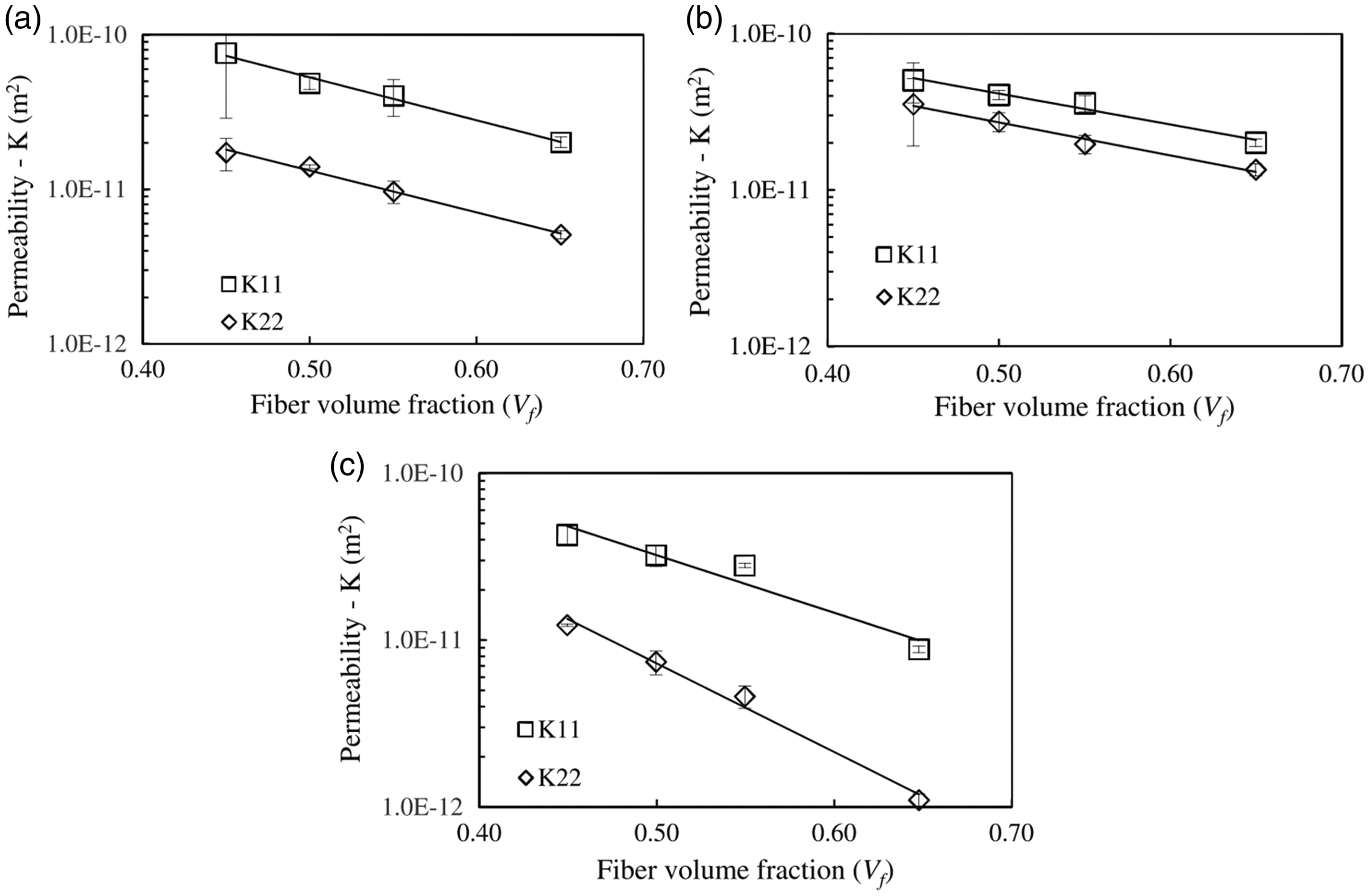
In-plane permeability of 3D fabrics: (a) orthogonal, (b) angle interlock, (c) layer-to-layer [107].
Ali et al. [128] presented a hybrid experimental–numerical methodology for predicting the in-plane permeability of preforms by using geometrical models generated from computed tomographic images. It proved that the preform permeability is also governed by the geometry of the channels available for resin flow. The flow field contours shown in Figure 17 are due to the obstruction provided by the through-thickness z-binder yarn, which plays a vital role in the resin flow process through the channels. In the weft direction, the resin passes through the gaps formed between the warp yarns as shown in Figure 17(a) and (b). Once the flow reaches the z-binder yarn, it changes the path to flow around the z-binder unlike the flow through the thickness where the z-binder yarns act like pathways for the resin [130]. The z-binder yarns cause a major obstruction for in-plane flow. As for the flow in the weft direction, the gaps in the warp direction also participate in the fluid transport process which can be seen in Figure 17(c) and (d). The obstruction caused by the z-binder yarns can be clearly seen in Figure 17(a) and (b), where the streamlines change the path, making way around the z-binder yarn.

The flow field contours, (a,b) streamline passing through the channels and around the z-binder yarns within the unit cell at T0, (c,d) three-dimensional velocity fields within the unit cell at T0 [128].
Endruweit [104] has measured experimentally the in-plane and through-thickness permeability of three different 3D woven reinforcements and showed that the in-plane permeability values were generally in the same order of magnitude as those in 2D fabrics. On the one hand, for in-plane permeability, the principal permeability values and the orientation of the principal permeability axes are characterized mainly by the dimensions of the inter-bundle voids in each layer, the pattern of the binder yarns, and the dimensions of the binder yarns. For the angle-interlock weave, the in-plane permeability reflects the nonlinear dependence of inter-bundle void dimensions on the level of compression. For the orthogonal weave, two permeability domains can be distinguished. While at low compression levels, fluid flow through gaps between the yarns on the fabric surfaces results in high permeability, the permeability is significantly lower for more uniform fabric impregnation at high compression levels. On the other hand, the through-thickness permeability of all studied 3D fabrics is higher than that of a typical 2D fabric. Flow-enhancing through-thickness channels in the structure of the 3D reinforcement are formed around the binder yarns. For each fabric layer, K33 is determined by the number of binder yarns per surface area, the binder yarn dimensions, and the angle between the binder yarn axis and the fabric plane. The dimensions and angle of the binder yarn and the dimensions of the inter-bundle voids in both fabric directions depend on the fabric compression.
In contrast, a study conducted by Mohamed and Wetzel [131] showed that 3D orthogonal woven fabrics offer significantly higher in-plane and through-thickness permeability properties than 2D fabrics at similar fiber volume fractions. Ngo and Tamma [132] used numerical techniques to predict the in-plane and through-thickness permeability characteristics of an orthogonal weave based on a 3D unit cell. Their results showed qualitative agreement with the experimental observations. Their simulations indicated that the in-plane permeability was higher than the through-thickness permeability.
Applications
Over the last decades, ranging from composites to body armour, dry 3DWIFs can be very useful in many technical applications. The mechanical properties of dry 3DWIFs can be a great knowledge base system in the application of both composite reinforcements and numerical model developments. As for composite reinforcements part, 3DWIFs constituted by commingled yarns can be formed at room temperature and this “cool” forming tends to be better controlled and seems to be more economical. Besides, complex final preform can be achieved, for example an oil pan used in various regular cars [133], 3D tubular, and the seat of truck [134]. A review about the mechanical behavior and analytical models of 3D woven polymer matrix composites has been carried out by Huang et al. [40]. But the dedicated part dealing with dry 3DWIFs is restricted to the common classification of 3DWIFs, and few descriptions was given about 3D weaving categories and process weaving and all the mechanical properties are based on the 3D woven composites rather than the dry 3DWIFs. Moreover, Gereke and Cherif [135] gave a review of numerical models for 3D woven composite reinforcements. This paper provides a wide review of existing finite element models used to describe the 3DWIFs. Developing models can be used for further investigations, e.g. the optimization of fabric structure and forming processes.
The 3DWIFs are also applied in the ballistic and knife protection as body armour. The recent research showing that the well-fit female body armour are obviously needed due to the physiological differences between men and women. Angle-interlock fabrics with different structural features are produced by Chen et al. [28] systematically to investigate their moldability for technical applications. Angle-interlock woven fabrics are proposed [85] as an alternative to the conventional plain woven fabrics in making female body armour due to their advantages in moldability without the need of cutting or folding and ease in manufacture. Dufour and Boussu [136] gave an improved knowledge of 3D warp interlock fabric during forming process using gusset. Moreover, Abtew et al. [137] developed the adaptive bust for female soft body armour using 3DWIFs by 3D design processes. Furthermore, a recent study supported [138] that 3DWIFs show better shaping ability according to the female contour while designing the body armour than its counterpart 2D plain weave p-aramid fabric. Finally, according to the result, fabrics types along their rigidity property were found to be a significant factor for designing women seamless female body armour.
Conclusions and future directions
In this present paper, the mechanical properties of 3DWIFs have been clearly recognized and systematically classified based on different mechanical performance, i.e. tensile, impact, compaction, bending, shear, and other properties. From the perspective of structure–property relationships, this review covers the recent and rapidly advancing subject of dry 3DWIFs according to the different process and product parameters chosen in the different research studies. Various mechanical properties can be achieved, providing a number of benefits which include: The methods for improving the tensile strength of 3DWIFs include a minimum waviness in the in-plane fibers which are affected by the weave architecture, increasing values of weft densities and linear density, and intra-layer hybridization at fabric level; Hybridization weave, similar warp and weft densities, and increasing the number of crossover points in the weave structures can be offered excellent impact energy absorption. Besides, it is better to use aramid fiber instead of PE fiber for the same soft ballistic protection; It is possible to increase the compaction ability of these fabrics with water lubrication and by increasing compaction temperature; An increase in the number of layers is an effective way of obtaining higher bending stiffness and bending hysteresis; An increase in the warp or weft density can be helpful to the shear rigidity of 3DWIFs.
These methods for improving the mechanical responses are highly desired targets in the design of new modern materials with advanced properties. From the above review of the previous studies, it is clear that existing reports have mainly focused on the relationship between the fabric architectures and the macro-scale mechanical behaviors. In other words, the detailed damage processes and the micro-scale damage characterizations within the 3DWIFs cannot be effectively tracked and detected. As such, it is undoubtedly difficult to understand the final failure mechanism of 3DWIFs subjected to different and complex damage.
Based on the principle of design, fabrication techniques, and the application conditions of the materials, four current challenges dominate the design of 3DWFs: It is essential to unify the classification of the 3DWIFs which can be compared and applied more widely; Although it has been studied for several decades, studies on failure mechanisms of these fabrics under different loads have not been so numerous; Some mechanical properties require further understanding, for instance knife penetration, the biaxial tensile test, and dynamic mechanical tests, for example, fatigue-resistance, or thermal-stability, such as fire-retardant properties, have not been conducted in 3DWIFs, which might be promising useful and advantageous by enhancing the properties and can extend the application of 3DWIFs. The current research merely falls on the properties in contrast with 2D laminates. There are very few papers about the mechanical properties between different types of 3DWIFs. The 3DWIFs can be applied in fire protection area. For example, we could design a 3DWIF structure (layer-to-layer) with different function of yarns in different layers. The fire-resistance yarns are used in the surface of layers, while the comfortable yarns are used in the layers contacted with human body. Besides, the 3DWIFs can also combine with the smart textiles. There is a huge space to explore with the help of the sensor, the shape memory fiber, or the phase change materials. The 3DWIFs can not only be applied in macroscopic field but also have potential applications in microscopic field, like medical area in the future. We could suggest that it could be woven by biocompatible nanofibers and combined with medicine as drug delivery system, which is a good way to treat internal injuries without surgery.
In conclusion, studies on the mechanical response of dry 3DWIFs have not been widely conducted in the open literature. Overall, the influent factors have not been studied thoroughly and there is still more performance to study and improve. The focus of future research should be on the different parameters and performances which in turn facilitate an in-depth exploration of the dry 3DWIF and explore the properties of 3DWICs. Further research is still required to optimize the structure and improve the mechanical properties of dry 3DWIFs. It is still possible to create new architectures of 3DWIF to envisage a range of applications over the next decade and generally accepted by the designers, manufacturers, and users of composites that will update with better functionality and overcome a number of technical, scientific, and economic challenges.
Footnotes
Acknowledgements
The authors wish to express their gratitude to the China Scholarship Council (Project no. 201708420167) for financially supporting this work.
Declaration of conflicting interests
The author(s) declared no potential conflicts of interest with respect to the research, authorship, and/or publication of this article.
Funding
The author(s) received no financial support for the research, authorship, and/or publication of this article.