
Abstract
This paper aims to identify the underlying physical mechanism for the compression deformation of a warp-knitted spacer fabric with a typical structure with experimental and theoretical studies. Compression tests were carried out to measure the load–displacement relationship of the fabric. The structural features of the spacer yarns were photographed by a microscope at different displacements during the compression test. A theoretical model based on elastica theory was developed to describe the compression behavior of the fabric by introducing the effect of complex geometry of the spacer yarns. A comparison between the experimental results and theoretical calculations was also conducted. Four distinctive stages including initial stage, elasticity stage, plateau stage and densification stage were identified and their underlying physical mechanisms were explained based on experimental observations and theoretical calculations. The model could provide an in-depth understanding on the deformations of spacer yarns of spacer fabrics under compression.
Introduction
Three-dimensional warp-knitted spacer fabrics consisting of two separate outer fabric layers joined together but kept apart by spacer monofilaments have been widely used in shoe uppers, mattress covers, cushions, impact protectors and automotive interiors due to their good air/moisture permeability and designable compressibility [1–6]. The demand for customization of their compression characteristic is increasing as the application of spacer fabrics extends in recent years. Spacer fabrics have a sandwich structure of which spacer monofilaments are the main load-carrier [3]. Hence, a theoretical model for describing the deformation behavior of spacer monofilaments can be used to predict the compression characteristic of an entire spacer fabric approximately.
Some efforts have already been made to numerically or analytically study the compression deformation behavior of a spacer monofilament for providing an efficient way to predict the compression characteristic of spacer fabrics. Vassiliadis et al. [7] reported a finite element (FE) model to simulate the post-buckling deformation of spacer monofilaments. Brisa et al. [8] presented an FE model for a vertical spacer monofilament of a thick spacer fabric under compression by taking the contacts between the spacer monofilament and the outer layers into account during the compression process. Hou et al. [9,10] also conducted an FE study on a spacer fabric. In their study, the geometrical shapes of the spacer monofilaments were calculated by a nonlinear buckling analysis from the manufacturing parameters, and the outer layers were modelled as two isotropic planes. Liu and Hu [11] reported an FE study on the compression behavior of a typical spacer fabric structure based on the precise geometry of a unit cell reconstructed from μCT scanning by fully considering the yarn interactions among all the fabric components and material's nonlinearity, and a satisfactory prediction of the compression load–displacement relationship of the fabric was achieved.
Whereas FE simulations could obtain better predication on the compression property, analytical model is more effective in providing the underlying physical mechanism of spacer fabric under compression. Renkens and Kyosev [12] developed a principle for creating the geometry of spacer structures based on an emulation of the real knitting process, knitting on a flat machine first and then transforming the loops to their proper places in the 3D space. Mokhtari et al. [13] proposed an analytical model by assuming a constant curvature along spacer yarn length during compression. Chen et al. [14] revised Mokhtari’s model by additionally introducing the contact between spacer monofilament and fabric outer layer. However, both Mokhtari’s model and Chen’s model ignored the fact that spacer yarns undertook post-buckling rather than pure bending. Helbig [15] reported an approximate explicit model based on force and moment equilibrium without considering the real spacer yarn shape. Bogdan and Zbigniew [16,17] established two models by treating a spacer monofilament as an initial straight slender elastic rod using Euler–Bernoulli beam theory with either pinned–pinned or fixed–fixed boundary conditions. The small deflection theory was used in the models, which is not consistent with the nature of the spacer monofilament undergoing a large deflection under compression. Later on, they revised the model by using the large deflection theory and considered the spacer monofilament as an elastica [18], but only vertical spacer yarns were considered in the model.
This paper presents a generalized model based on elastica theory in order to identify the compression mechanism of warp-knitted spacer fabrics. The model was developed to calculate the force–displacement relationship of spacer fabrics and to obtain the deformed shapes of spacer monofilaments during compression process. A typical warp-knitted spacer fabric was manufactured to verify the model. The theoretical calculations were evaluated and compared with experimental results.
Structural analysis of spacer fabric
A warp-knitted spacer fabric with a typical structure was used in this study. It was produced on a GE296 (RD6) E18 high speed double-needle bar Raschel machine of gauge 18, Changzhou Wujin Wuyang Textile Machinery Co., Ltd, which is equipped with six yarn guide bars as shown in Figure 1. The lapping movements and materials used for each guide bar are listed in Table 1. The multifilament created the binding of the structure in the knitting process by GB1, GB2 for top layer and GB5, GB6 for bottom layer, respectively. Spacer yarns of polyester monofilament connecting the two outer layers form the spacer layer by GB3 and GB4.

Principle of knitting spacer fabrics on a double-needle bar Raschel machine.
Lapping movements and yarns used for the warp-knitted spacer fabric.

To obtain a clear view of the spatial configuration and arrangement, schematic diagrams of the spacer monofilaments according to the lapping movements of GB4 both on the machine and off the machine within a three dimensional global coordinate system OXYZ are shown in Figure 2. The vertices of the box represent the binding stitch of the outer fabric layers and the plane XOY represents the back needle bar and bottom layer. The top plane of the box which is parallel to plane XOY represents the front needle bar and top layer. Another spacer monofilament formed by GB3 is completely symmetrical to that of GB4. Therefore, the two types of spacer monofilaments shown in Figure 2 can represent all the elements of the spacer layer. It can be seen from Figure 2(a) that yarn 1# fabricated by notation 1-0/1-0 is in the plane YOZ and yarn 2# fabricated by notation 3-2/1-0 is in the plane XOZ. In view of these geometrical relationships, the length of the spacer monofilament can be calculated according to the machine setting parameters. The initial distance between back and front needle bars was 11.9 mm. After removal from the machine, the thickness of the spacer fabric is changed to 7.52 mm, meanwhile the yarns turned into curved form as shown in Figure 2(b). By carefully examining the fabric, it can be found that the plane formed by yarn 1# is in the plane of YOZ and the plane formed by yarn 2# is perpendicular to plane XOZ. These geometrical relationships are illustrated in Figure 2(b).

Schematic diagram of the arrangement of spacer yarns: (a) on the machine; (b) removal from the machine.
The structural parameters of the machine setting and the warp-knitted spacer fabric defined in Figure 2 are listed in Table 2. Loop height, loop width and thickness of the fabric on the machines are a0, b0 and h0, respectively. After removal from the machine, the three structural parameters become a, b and hf. L1 and L2 are the lengths of the yarn 1# and yarn 2#, respectively.
Structural parameters of the machine setting and the warp-knitted spacer fabric.

Compression test and analysis
Figure 3 shows a typical compression load

Compressive load–displacement curve of the spacer fabric.

Cross-sectional microscopic pictures of the spacer fabric, (a) course-wise; (b) wale-wise.
In the initial stage of deformation, a lower slope is due to the compression of the loose outer layers and no effective constraint on the spacer monofilaments. Polyester monofilament in the fabric is continuous but includes two parts. The first part is spacer yarn which is the main load carrier of the fabric. The second part is monofilament loop in the outer layers which is wrapped by multifilament loops. The loose multifilament stitch around a monofilament cannot constrain the monofilament securely in the initial stage of the compressive deformation. As a result, slippage among multifilament loops and monofilament loops occurred in this stage. The intermeshed monofilament loops can also slip, and the length of monofilament loops in the outer layers increases gradually by moving the spacer monofilament to the monofilament loop. Meanwhile, the total length of spacer monofilament decreases gradually. The expansion of monofilament loop could make the loose multifilament stitch tight at the end of stage I. There is an obvious transition from flexible to stiff behavior in the slope of the load

A generalized flexible slender elastic rod under applied end loads and moments.
Modelling and simulation
Formulations for initially straight elastic rod
A model describing the compression process and predicting the load–displacement relationship is important to get an in-depth understanding on the compression mechanism. Initially, straight spacer yarns on the machine turn to the curved form when the fabric removes from the knitting machine due to the reduction in the distance of the outer fabric layers without tension. The spacer yarn is made from monofilament which can be treated as flexible slender elastic rod. Therefore, the curving process is almost elastic buckling and can be mathematically modeled by elastica theory. In doing so, some assumptions are made as follows: (1) the monofilament is homogenous and elastic material; (2) the diameter and weight of the monofilament are neglected; (3) the thickness of the outer fabric layer is neglected; (4) the contacts between outer layer and monofilaments are assumed to be hard and friction between them was neglected.
Consider the general flexible slender inextensible elastic rod which is initially straight and buckled by the applied vertical end force P, horizontal end force Q, and end moments M1 and M2 as shown in Figure 5. The global coordinate system is used as
The moment equilibrium equation of this elastic rod is
The moment required for equilibrium at any general point 
Referring to Bernoulli-Euler Law, the following system of equations termed elastica can be established

Multiply the above equation by dθ and integrate to obtain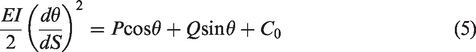
Rearranging this expression gives
This is an expression for the curvature of the elastic rod at any point.
Thus
Substituting this curvature expression into the moment–curvature relationship will constitute an expression for the moment at any angle along the elastic rod. It is
From the geometrical relationships, integrate over the length of the elastic rod, i.e. the whole range of θ where 
By using the change of variables and integrals transforms, the above equations can be transferred to nonlinear algebraic equations containing elliptic integrals of first and second kind. The integrals 
To apply the elliptic integrals, Shoup [19] made the following changing of variables

By using the above variables and integrals transforms, the complete governing nonlinear equations for the initially straight elastic rod in the null form become
The coordinates (X, Y) of an arbitrary point on the elastica curve corresponding to 
The buckled rod shape can be drawn by using the coordinates of the points in the range of
The dynamic process of the spacer yarns changing from initially straight into curved form might include outer fabric layer shrinking, spacer yarn buckling and slipping. This process is very complicated and therefore the exact deforming behavior is not easy to address; however, the buckled yarn in steady state obeyed the above model.
Structural parameters acquisition for the model
To conduct the numerical simulation for the spacer yarns, the parameters involved in equation (14), i.e. EI, W, H, L,
The bending rigidity EI of the polyester monofilament is equal to 0.6836 ±0.0384 cN/cm2 which was tested by KES-FB2 pure bending tester. The parameters W, H and L involved in equation (14) for spacer yarns 1# and 2# are listed in Table 3 which can be easily obtained from geometric relationships as shown in Figure 2 and the data are given in Table 2.
Structural parameters of the spacer yarns in steady state.

From the geometric shape of the spacer yarns, it is obvious that the boundary conditions of the two ends of the spacer yarn are close to pinned–pinned case. In this case, the moments at the ends of the spacer yarns are assumed to be zero. Thus, the two inflection points ϕ1 and ϕ2 of the first mode of the buckled curve are at π/2 and 3π/2.
Initial shape of the spacer yarns
All the parameters required by equation (14) are listed in Table 3. These equations are typical nonlinear algebraic equations containing elliptic integrals of first and second kind. Here, five unknowns and five nonlinear algebraic equations can be solved by Newton’s method. Numerical solutions were obtained using a Newton’s method with the subroutine FindRoot in Mathematica® 7 for students. Substituting the results of equation (14) into equation (15), the shape curves of the spacer yarns were obtained as shown in Figure 6(a). These curves were also rotated and moved in a three-dimensional space to form the spacer layer of the fabric as shown in Figure 6(b).

Calculated shape curves: (a) spacer yarn 1# and spacer yarn 2#; (b) spacer layer of the fabric assembled by the curves.
Compression process analysis
The static load analysis diagram for the two spacer yarns is shown in Figure 7. For spacer yarn 1#, the load P in Z-axis totally contributes to the compression resistance of the fabric. In contrast, the load P of spacer yarn 2# is not along Z-axis, and only the component force Pz contributes to the compression resistance of the fabric. As the fabric thickness decreases in compression, the angle between P and Pz for spacer yarn 2# in Figure 7 increases. Therefore, the proportion of load P contributes to the compression resistance decreases in compression. Besides, the spacer yarns will contact the outer layers when the applied displacement rises up to a certain value; their different initial shapes lead to different contact behaviors. In this connection, the compression process of the two spacer yarns should be studied separately.

Force analysis for the two spacer yarns.
The spacer yarn 1# is discussed first. A local coordinate system xoy is selected as illustrated in Figure 7. Because the load P is governed by equation (14), by varying the parameter H, the corresponding reaction load can be calculated. For this particular spacer yarn, the parameter H equals the fabric thickness hf. Reducing the value of H in equation (14) means decreasing the fabric thickness and thus used to simulate the compression deformation process of the spacer yarn 1#.
It should be noted that, for governing Equation (14), constraints are only imposed at the two endpoints of a spacer yarn. Spacer yarn 1# will contact the outer layers when reaching a certain displacement, providing additional constraints on the spacer yarn, thereby affecting its mechanical behavior. Such contacts were considered in the calculation. Spacer yarn 1# presented in Figure 7 can be divided into three sections: two end sections (top and bottom) and a middle section. Due to its asymmetrical initial shape, there are three phases of deformation: (i) free post-buckling, (ii) the bottom end section in contact with the bottom outer layer and (iii) the top end section in contact with the top outer layer. To conduct the calculation, the two dividing points among the three phases should be identified.
At the beginning (Phase i), the entire spacer yarn 1# undertakes post-buckling freely. The inclination angles with the x-axis at the two endpoints (i.e. θ1 for the bottom endpoint and θ2 for the top endpoint as defined in Figure 5) increase with the displacement. Spacer yarn 1# does not contact the two outer layers, keeping a constant effective length in post-buckling in this phase.
Compressing spacer yarn 1# to be of a specific displacement, at the beginning point of phase ii, the bottom end section starts to contact the bottom outer layer. At this moment, the inclination angle with the x-axis at the endpoint of the bottom end section θ1 equals π/2 due to the pinned constraint. From then on, line to surface contact occurs. The contact length between the bottom end section of the yarn and the bottom outer layer increases as the displacement increases; meanwhile, the effective length of the yarn in post-buckling decreases. Since the line contact part of the bottom end section does not contribute to the compression resistance any more, it is excluded in the calculation. In this way, as the displacement increases, the endpoint of the bottom end section is moving to the point that is about to contact the bottom outer layer, and the angle θ1 is keeping constant being π/2 in this phase.
During the phase ii, the inclination angle with the x-axis at the endpoint of the top end section θ2 also increases. The top end section of the spacer yarn 1# starts to contact the top outer layer when this angle rises to −π/2 with increasing the displacement. This is the beginning point of phase iii. After that, the shape of the non-contact part of the spacer yarn keeps constant, but varies in scale. Its top and bottom end sections are exactly symmetrical in post-buckling and contacting with the outer layers.
The two beginning points of the phase ii and phase iii correspond to the changes of the boundary conditions of the two endpoints. In order to address the mechanical response and geometric deformation process of this spacer yarn under compression, the parameter H (or displacement) at these two critical points should be calculated first. For the first beginning point, the relevant parameter H is calculated by assuming θ1 being π/2. For the second beginning point, it is calculated by assuming θ2 being −π/2. Then the calculations can be carried out, and the results are presented in Figure 8.

Numerical results of spacer yarn 1#: (a) effective length; (b) angles at endpoints; (c) shape factor k; (d) reaction load P.
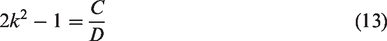
In the phase i, the effective length of spacer yarn 1# in post-buckling keeps constant being 11.965 mm (Figure 8(a)), whereas the angles at the two endpoints increases with the displacement (Figure 8(b)). The parameter k defined by equations (12 and 13), the modulus of the elliptic integral, is a shape factor determining the elastica shape. It varies through this phase, implying the shape change of the spacer yarn (Figure 8(c)). Meanwhile, the reaction load P increases slightly (Figure 8(d)). In the phase ii, the effective length decreases due to the contact between the bottom end section of the spacer yarn and the bottom outer layer (Figure 8(a)), while the angle at the bottom endpoint θ1 keeps constant being π/2, but the angle at the top endpoint θ2 increases (Figure 8(b)). The spacer yarn shape changes through this phase, according to the shape factor k (Figure 8(c)). At the same time, the reaction load P increases gradually (Figure 8(d)). In the final phase, both the two end sections are in contact with the outer layers. Its effective length decreases rapidly (Figure 8(a)), but the two angles at the two endpoints keep constant (Figure 8(b)). In addition, the spacer yarn shape in post-buckling remains and just changes in scale during this phase (Figure 8(c)), while the reaction load P rises dramatically (Figure 8(d)).
A local coordinate system xʹoʹyʹ is selected for spacer yarn 2# as illustrated in Figure 7. It should be noted that the parameter H for spacer yarn 2# is not identical to the initial fabric thickness hf. Spacer yarn 2# has a symmetrical initial shape, so there are only two phases of deformation: (i) free post-buckling, (ii) two end sections in contact with the outer layers simultaneously. In the phase i, the entire spacer yarn undertakes post-buckling freely (Figure 9(a)), while the inclination angles with the xʹ-axis at the two endpoints (θ1 and θ2) increase with the displacement (Figure 9(b)). No contact is involved, and the shape changes through this phase (Figure 9(c)). The reaction load P increases slightly, while the component load Pz contributing to the fabric compression resistance has a lower slope (Figure 9(d)). When the spacer yarn is compressed by a further displacement of a specific value, the two end sections start to contact the outer layers simultaneously, being the beginning point of phase ii. The effective length decreases rapidly (Figure 9(a)), and the inclination angles at the two endpoints θ1 and θ2 are equal to π/2 and −π/2, respectively, due to the pinned constraints (Figure 9(b)) in this phase. In addition, the spacer yarn shape keeps constant but just changes in scale (Figure 9(c)). The reaction load P increases sharply, but the component load Pz contributing to the fabric compression resistance rises gradually (Figure 9(d)).

Numerical results of spacer yarn 2#: (a) effective length; (b) angles at endpoints; (c) shape factor k; (d) reaction load.
The shape changes of spacer yarns 1# and 2# in the compression process with the selected local coordinate systems xoy and xʹoʹyʹ, respectively, are shown in Figure 10. It gives the side view observed from the coursewise direction, in which the compression phases and the corresponding fabric thicknesses (hf) are annotated, demonstrating the detailed deformation process. The compression process of spacer yarn 1# in Figure 10 agrees well with the deformation observed in the experiment as shown in Figure 4(b). Both of the calculated and real deformation experienced three phases: free post-buckling, line-to-surface contact with bottom layer, line-to-surface contact with top layer.

Buckled shapes of spacer yarns at different thicknesses: (a) Spacer yarn 1#; (b) Spacer yarn 2#.
To compare the theoretical results with the experimental data, the load–displacement relationship of the two yarns has to be converted to the one for a specimen with dimensions used in experiment (100 mm × 100 mm). According to the area density of the fabric, a specimen with area of 100 mm × 100 mm includes 4114.8 needle loops. Therefore, the theoretical load of the fabric is 4115 times of the summation of spacer yarn 1# reaction load and spacer yarn 2# component load along Z-axis.
Figure 11 gives a comparison between the theoretical and experimental load–displacement curves. For the theoretical curve, the loads at the initial state of the two spacer yarns were subtracted to eliminate the initial curvature effect. A remarkable deviation between the theoretical and experimental results can be observed in the initial, linearly elastic and plateau stages. In the densification stage, moderate agreement is achieved.

Comparison of load–displacement curves of spacer fabric for experiments and theoretical calculation.
The big differences in the initial, elastic and plateau stages between the theoretical and experimental results might be due to the assumptions made in the analytical model not considering the precise geometric structure of the spacer fabric and the physical properties of the knitted yarns. The differences between the real and theoretical fabrics and how these differences affect the theoretical result are summarized as follows: The spacer monofilament diameter, and the outer layer thickness and morphologies were neglected in the calculation, leading to an overestimate of the spacer yarn lengths. Obviously, a longer spacer yarn results in a lower reaction load. Besides, in reality, the two spacer yarn end sections contact the outer fabric layer internal surfaces. The outer layer thickness and morphologies will affect the contact behavior. More specifically, the spacer yarns contact the internal surfaces at a smaller displacement in the real-life test than that in the predicted process. That is one reason why the theoretical loads are lower than the experimental loads. The contacts and friction among spacer yarns were neglected. These contacts could effectively affect the boundary conditions of the spacer yarns, and thus the experimental result differs greatly from the theoretical one. The intricate structure of the outer layers was not considered, possibly neglecting more complex constraints on the spacer yarns. This model only takes the simply support pinned constraint into account; out-of-plane deformation is not allowed for the spacer yarns. In reality, the constraints imposed on the spacer yarns by the outer layers can change during the compression. The assumption, which cannot describe the interactions between the outer layers and spacer yarns as in real-life specimens, can affect the theoretical result.
Conclusions
Experimental and theoretical studies were used to investigate the compression mechanism of a typical warp-knitted spacer fabric. The experimental results indicated that the compression behavior of the spacer fabric can be divided into four main stages. The analytical model was employed to calculate the initial and buckled shapes of spacer yarns in compression and load–displacement curve. It was found that the compression mechanism of the spacer fabric is affected by its loose structure of outer layer, buckling of monofilaments as well as the contacts between monofilaments and outer layers. Although the model does not give an accurate prediction on the load–displacement relationship, it provides a theoretical way to study the compression properties of the fabric based on its complicated structure and mechanical properties of its components. With the model, it is possible to separately analyze these effective features that would be impossible in real-life experiments, and to obtain a deeper understanding of the compressive behavior of warp-knitted spacer fabrics.
In future work, different boundary conditions in different compression stages should be employed as well as the diameter of the monofilament and the thickness of the outer layer should be considered to achieve a better agreement between the theoretical and experimental results.
Footnotes
Declaration of conflicting interests
The author(s) declared no potential conflicts of interest with respect to the research, authorship, and/or publication of this article.
Funding
The author(s) disclosed receipt of the following financial support for the research, authorship, and/or publication of this article: The work described in this paper is sponsored by the National Natural Science Foundation of China (11702062), Shanghai Pujiang Program (17PJ1400300), Fundamental Research Funds for the Central Universities (16D110120), and initial research funds for Young Teachers of Donghua University (101-07-0053036).