
Abstract
A set of radar absorbent carbon/quartz fiber hybrid core-spun yarns (9B, 12B17A, and 12B25A) with different braided structure (round and flat) and braiding angle (17° and 25°) were designed, and then the mechanical and electromagnetic properties of the corresponding 2.5D core-spun yarn/epoxy composites (9BC, 12B17AC, and 12B25AC) were investigated in this study. The results showed that the composite made by round core-spun yarns with large braiding angle (12B25AC) had the highest mechanical properties and the best radar absorbing properties in the three types of 2.5D core-spun yarn/epoxy composites. The effective absorption bandwidth (reflection loss < −10 dB), maximum reflection loss value, tensile strength, and bending strength of the 12B25AC was 3.9 GHz (14.1–18 GHz), −17.2 dB at 16.7 GHz, 428.43 MPa, and 545.10 MPa, respectively. Therefore, the 2.5D reinforced composite by the round core-spun yarns with large braiding angle offers a unique architectural method to attain both outstanding radar absorption and mechanical performances.
Introduction
With the rapid development and extensive use of the electronic equipment, the absorption and the interference shielding of electromagnetic (EM) wave have gradually become very important issues for commercial and military purposes [1,2]. The stealth technique is an effective mean to improve the absorption and the interference shielding of EM wave, which has been highly acknowledged by many countries in the world [3]. At present, the stealth technique can be categorized into two methods: one is to reduce the scattering of the incident EM wave through shape optimization (shape stealth), and the other is the use of radar-absorption materials (RAM) [4–6] and/or designing the radar-absorbing structures (RAS) [7,8]. In the early stage, researchers mainly concentrated on the shape stealth and the RAM, but nowadays more and more researchers are focused on the RAS [9,10].
Carbon fiber (CF) reinforced polymer composites are widely used as structural parts in aerospace area due to their high specific strength and stiffness, especially in the warplanes [11]. In theory, CF is an electric loss RAM [12], but continuous CF is the strong reflector of EM waves due to its high graphitization degree in practice [13,14]. In order to make full use of the excellent mechanical property of CF and to improve the stealth performance of the composite, many researchers mixed CF with absorbing fibers (graphite, metal, and SiC fibers) or transmissivity fibers (glass, Kevlar, boron, and/or silicon nitride fibers) together to reinforce composite [13,15,16]. The hybrid fiber reinforced composites mainly include interlaminated hybrid composite, in-plane hybrid composite, and interlaminated and in-plane hybrid composite. It is known that the laminated composite structures are prone to delamination damage when they suffer from external stress [17]. However, the mechanical and absorbing properties of RAS should be considered simultaneously [18,19].
The three-dimensional (3D) textile composites were developed to overcome the easy layering shortcoming of laminated composites [17,20–22]. As an important branch of the 3D textile composites, 2.5D woven composites can be mass produced at a low cost using automated manufacturing techniques and provides higher delamination resistance than laminate composites [23,24]. 2.5D angle interlock woven fabric as one of the reinforcements of 2.5D woven composites is composed of straight weft yarns and a series of undulated warp yarns. The warp yarns can be bound to different depth where various arrangements of weft yarns placement which can be used to produce a wide range of these types of composites [25]. Therefore, designers could produce the optimal 2.5D woven fabrics for required mechanical properties.
The current hybrid types are the simple arrangement of two or three kinds of fibers in one layer or in different layers or weaving the CF with other fibers in a fabric. The absorbing fibers or transmissivity fibers are often at the top layers to match EM wave, and the CFs are as the inner layers to absorb the EM wave [17,26]. However, the enhanced effect of the radar absorbing is limitted. At this moment, core-spun yarns reinforced composite has attracted our attentions. This is because the core-spun yarn structure not only can obtain high tensile properties [27] through rational design, but also can meet the design requirement of hybrid fiber reinforced absorbing materials. For example, the CF can be as the core yarns to provide the high mechanical properties and absorbing properties, and the cover yarn can choose the absorbing fibers or transmissivity fibers to match the EM wave. To the best of our knowledge, many references had researched the core-spun yarns or hybrid yarns [27–31]. However, at present, no research on the mechanical and EM properties of 2.5D structural composite which produced by core-spun yarns.
Hence, in order to obtain a kind of structural absorbing composite with excellent mechanical properties and good absorption capacity. We designed three types of core-spun yarns with different braided structure (round and flat) and different braiding angle (17° and 25°) by hybrid CF and quartz fiber (QF). CF was used as the core yarn and QF was used as the braided yarn in the core-spun yarn, respectively. Then, three types of the 2.5D CF/QF core-spun yarns/epoxy composites were manufactured and their mechanical and EM properties were investigated. A universal testing machine was used to test the mechanical properties of the composites. The EM properties of the composites over the 8–18 GHz bandwidth were tested by the waveguide method in this work.
Experimental procedure
Materials
Basic properties of the raw materials.

CF: carbon fiber; QF: quartz fiber.
Weaving and curing process
Flat structural core-spun yarn (described as 9B) was fabricated by the KBL-9-4-90 braiding machine (Xuzhou Henghui Braiding Machine Co., Ltd, China). Figure 1(a) presents the braided yarns movement route image of 9B. And two types of round structural core-spun yarns with different braiding angle (described as 12B17A and 12B25A) were fabricated by the KBL-24-2-90 braiding machine (Xuzhou Henghui Braiding Machine Co., Ltd, China). Figure 1(b) shows the braided yarns movement route image of 12B17A and 12B25A. Table 2 lists the process parameters of the three types of core-spun yarns. Figure 2(a) presents the schematic diagram of CF/QF hybrid core-spun yarn structure.
The movement route images of braided yarns: 9B (a), 12B17A (b), and 12B25A (b). Schematic diagram of CF/QF hybrid core-spun yarn structure (a) and 2.5D structure (b). Process parameters of three core-spun yarns. CF: carbon fiber; QF: quartz fiber.


The technological parameters of three types of the 2.5D fabric preforms.

QF: quartz fiber.
The epoxy resin was JC-02A, JC-02B, and JC-02C, mixing them together by weight ratio of 100:85:1, and then vacuum assisted resin transfer molding (VARTM) process was used to make the composites. The process involved placing the 2.5D fabric (250 mm×185 mm×4 mm) into their own mold, closing the molds, checking them for leaks, and heating them to 40℃. Once the molds and the pipework connected to the molds were sufficiently heated, a vacuum of approximately 0.3 MPa was applied to the molds and the resin trap were allowed to stabilize for 5 min, and then the resin was injected into the molds. The injection process was continued until a sufficient volume of resin was seen in the resin trap, to indicate that the molds had been completely filled with resin. The molds were isolated from the resin pot and the resin trap and then put into an air-circulating oven. The manufacturer recommended cure cycle was employed: the first step of the cure cycle was 2 h at 90℃, followed by 1 h at 110℃, with the final step being 6 h at 135℃. The fiber volume fraction of the three types of 2.5D composites were approximate 50%.
After curing, the three types of composites manufactured by 9B, 12B17A, and 12B25A were described as 9BC, 12B17AC, and 12B25AC, respectively. The large pieces of the composite were cut into the EM absorption samples (30 mm×25 mm×4 mm), tensile samples (250 mm×25 mm×4 mm), and bending samples (80 mm×15 mm×4 mm) with the CNC water jet cutting machines (Shenyang All-Powerful Science and Technology Joint Stock Co., Ltd, China). Then the longitudinal morphologies of the core-spun yarns and the 2.5D composites were observed using a digital microscope (VHX-5000, Keyence, Japan). Figure 3(a) to (c) shows the typical longitudinal images of the core-spun yarns. It can be seen clearly that the QF in the core-spun yarns are the braided yarns. Figure 3(d) to (f) is the cross-section microscope pictures along weft direction of the three types of 2.5D composites. It was clear to observe that there were different bending degrees of the three types of core-spun yarns in their composite. This phenomenon was caused by the difference of core spun yarns and weft density. On one hand, the bending degree will increase with the increasing of weft density in the 2.5D composite. On the other hand, for round core-spun yarn, the core-spun yarn will become “harder” with the increasing of braiding angle, which can resist the warp yarns tension effectively. Among the three types of 2.5D composite, the weft density of 12B25AC is smallest (5.1 yarn/cm) and the braiding angle of 12B25A is largest, so the bending degree of weft yarns is smallest. For 9BC and 12B17AC, despite the weft density of 9BC is smaller than that of 12B17AC, but structure of 9B is flat and the braided yarns could not wrap the core yarn very well, when subjected to warp tension it tends to bend more easily. So, the weft bending degrees of 9BC is the largest.
Picture of core-spun yarns: 9B (a), 12B17A (b), and 12B25A (c) and photomicrographs of side faces along weft direction of 2.5D composites: 9BC (d), 12B17AC (e), and 12B25AC (f).
Test
Tensile and three-point bending properties were tested with a universal testing machine (Shenzhen Suns technology Co., Ltd, China) following ISO-527-5 and ISO 14125-1998, respectively. The loading rates were 2 mm/min. For each property, three samples were tested, and the average value was taken. The fracture morphologies of samples were observed by the Ultra-field microscopy system (VHX-5000, Keyence, Japan).
A waveguide measurement system was used to evaluate the broadband EM characteristics of the composite following ASTM D4935-18. It was composed of two coaxial cables, a waveguide tube for a broadband frequency range of 8–18 GHz, a data acquisition system and a vector network analyzer (Agilent Technologies, N5232A, CA, USA). The network analyzer consisted of a synthesized sweeper and a scattering parameter (S-parameter) test set. The S-parameter test set in the network analyzer was linked to the waveguide tube through precision coaxial cables. A schematic configuration of the waveguide measurement system of the experimental setup is shown in Figure 4. The test sample was illuminated with a polarized EM wave at normal incidence and the reflection and transmission were investigated by measuring the reflection S-parameter (S11 or S22) and transmission S-parameter (S12 or S21) with the waveguide measurement system. The EM wave struck the composite surface in the perpendicular to the weft yarn direction. In order to ensure the accuracy of EM testing, the specimen should be perfectly fitted to the sample holder.
Schematic configuration of the waveguide measurement system.
Results and discussions
Tensile property
Figure 5 shows tensile load–displacement curves of the three types of core-spun yarns. It can be seen that both tensile load and displacement of 12B25A were higher than those of 12B17A and 9B. This was because the fiber ratio of braided yarn would increase with the increasing of braiding angle in round core-spun yarn (Table 2), which is conductive to enhance the tensile load and displacement of the yarns. For flat core-spun yarn (9B), the core yarn could not be uniformly wrapped by the braided yarns (Figure 3(a)), unevenness of structure easily effects the strength of the yarns. In this case, the tensile property of 9B is the worst in the three types of core-spun yarns.
Tensile load–displacement curves of the three types of core-spun yarns.
Figure 6 shows typical tensile load-displacement curves and fracture morphologies after tensile failure obtained from the three types of 2.5D composites. Three types of 2.5D composite exhibited a similar variation tendency and all curves can be divided into three phases (I, II, and III). During the elastic deformation stage (phase I), the fiber and epoxy resin were bonded well so that the tensile property increased linearly under the external load. The matrix was destroyed firstly with the increase of load because of the lowest modulus in the composites (Table 1). When the load increased, the matrix was gradually destroyed, and the crooked yarns in the composite were gradually straightened as shown in the phase II. With the load increased, the matrix was completely destroyed and the yarn became the main load-bearing body, so the curves continue to increase linearly until the composites were collapsed (phase III). Among the three types of 2.5D composites the displacement of 12B17AC (5.38 mm) was largest, followed by 12B25AC (4.75 mm), and 9BC (4.59 mm) was the smallest. This was attributed to the bigger bending degree of weft yarns in 12B17AC (Figure 3(e)), so the displacement of phase II of 12B17AC (0.93 mm) was longer than that of 12B25AC (0.5 mm). However, for 9BC, though the bending degree of weft yarns was the largest (Figure 3(d)), but the displacement was the smallest. This was probably because the friction loss of 9BC in the preparation was too large, resulting in the yarns were broke before it was fully stretched in phase II. On the other hand, in the tensile test, when the load reached a certain value, the sample began to emit a slight noise. With the load increased, breaking the material suddenly at the peak value (29.5 KN for 9BC, 34.8 KN for 12B17AC, and 45.6 KN for 12B25AC, respectively) and the fracture is basically flat (as shown in Figure 6(a) to (c)). It means that the fiber was not pulled off gradually but almost simultaneously, which reveals the superiority of 2.5D structure that the delamination and split cracking like the traditional laminated composites were not found [17].
Tensile load–displacement curves and fracture morphology after tensile failure of the three types of 2.5D composites.
Figure 7 presents the tensile strength and modulus bar graphic of the three types of 2.5D composites. Comparing 9BC with 12B17AC, their structures of core-spun yarns are different. The average tensile strength of 12B17AC was 324.60 MPa, which was 7.4% higher than that of 9BC (Figure 7(a)), but the tensile modulus was basically the same. This was because the braided yarns could not wrap the core yarn very well in the flat core spun-yarn (Figure 3(a)), which caused friction loss in the core yarn during the processing of manufacturing the composite. Furthermore, the abrasion of core yarn leads to a decrease in the overall tensile property of 9BC. Conversely, the core yarn could be wrapped well by the braided yarns in the round core spun-yarn (Figure 3(b)). Accordingly, the abrasion of the core yarn could be prevented and the bending degree was smaller (Figure 3(e)) than that of the flat core-spun yarn (Figure 3(d)) while manufacturing the composite. Above all, the tensile property of 12B17AC was better than that of 9BC.
Tensile strength (a) and modulus (b) bar graphic of the three types of 2.5D composites.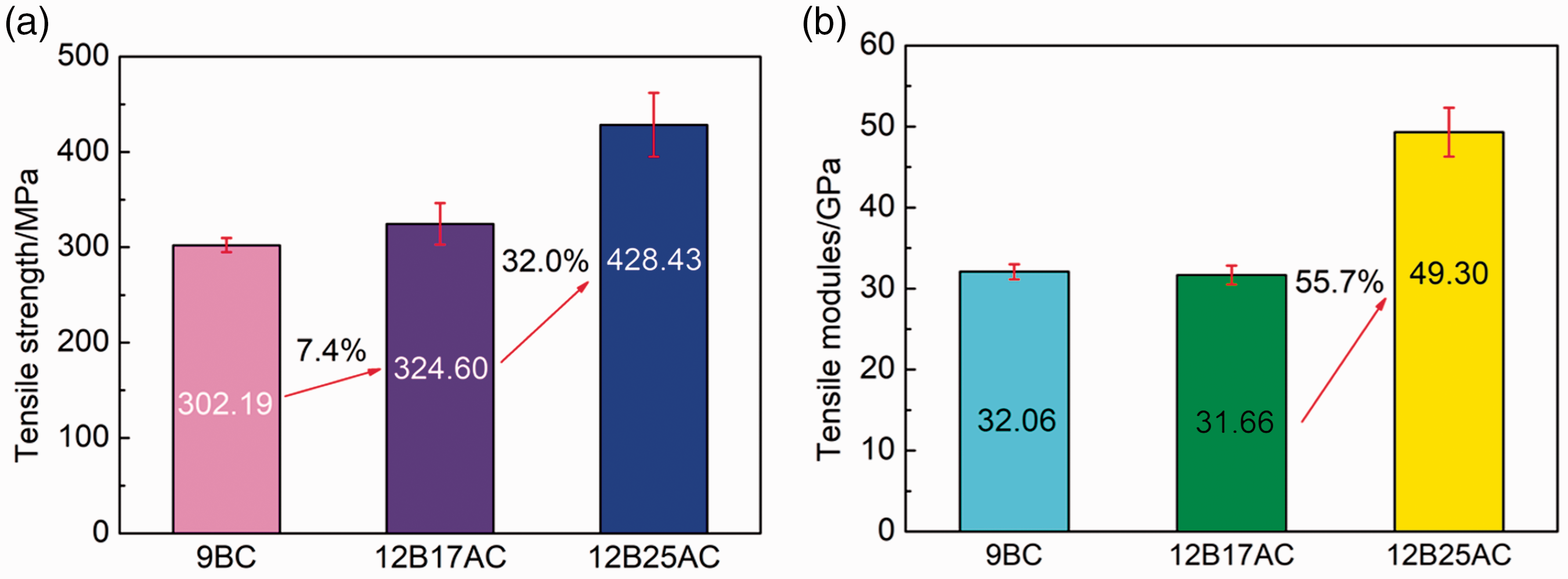
For 12B17AC and 12B25AC, they have same core-spun yarn structure (round) but different braiding angle. The 12B25A has a large braiding angle and its corresponding composite (12B25AC) shows better tensile property. The average tensile strength and modulus of 12B25AC were 428.43 MPa and 49.30 GPa, respectively, which were 32.0% and 55.7% higher than those of 12B17AC (Figure 7). Because the core yarn has to be wrapped well by the braided yarns in 12B25A, there was smaller bending degree for the core-spun yarn bounded by warp yarns in it. Hence, the core yarn could fully present its mechanical properties. However, for 12B17A, the core yarn is easy to expose when the composite has been manufactured (as shown in Figures 8 and 9(b)) due to the small braiding angle. Therefore, the bending of core yarn is more serious, which results in the better tensile property of 12B25AC. The tensile test results of 2.5D core-spun yarn/epoxy composites have similar comparison with those of the core-spun yarns.
Inner yarn of 12B17A is exposure: schematic picture (a) and product picture (b). The surface pictures of three types of 2.5D performs manufactured by 9B (a), 12B17A (b), and 12B25A (c), respectively.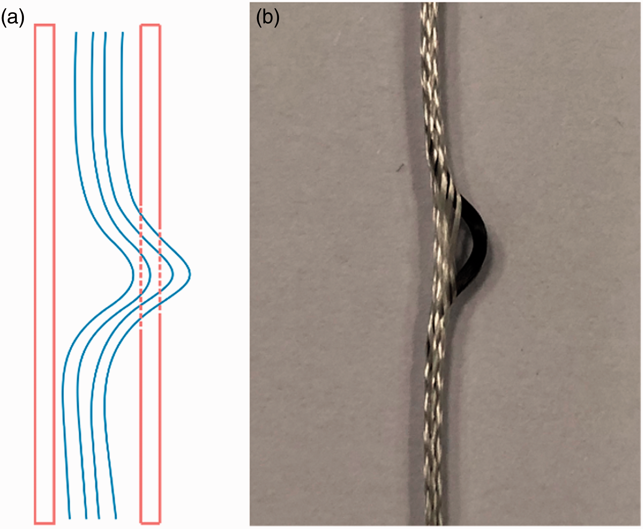

Bending property
The three-point bending load–displacement curves and fracture morphologies after bending failure of the three types of 2.5D composites are shown in Figure 10. The bending load–displacement curves of the three types of composites show a similar trend. In the bending experiment, the compression on the upper surface and the tension on the lower surface were formed when the sample was subjected to external forces. In the initial stage, the curves increase linearly because of the excellent integrity of the material. The epoxy resin began to break firstly since the strength of epoxy resin is much less than that of CF and QF (Table 1). Then the curves no longer increased linearly but rose undulately when the loading increased to a certain value (630 N for 9BC, 945 N for 12B17AC, and 1264 N for 12B25AC, respectively). There is no instantaneous damage and interlayer destruction (Figure 10(a) to (c)) in the entire bending test, which shows that the 2.5D core-spun yarn fabric has a good toughening effect and the interlaminar property of the composites is excellent.
Bending load–displacement curves and fracture morphology after bending failure of the three types of 2.5D composites.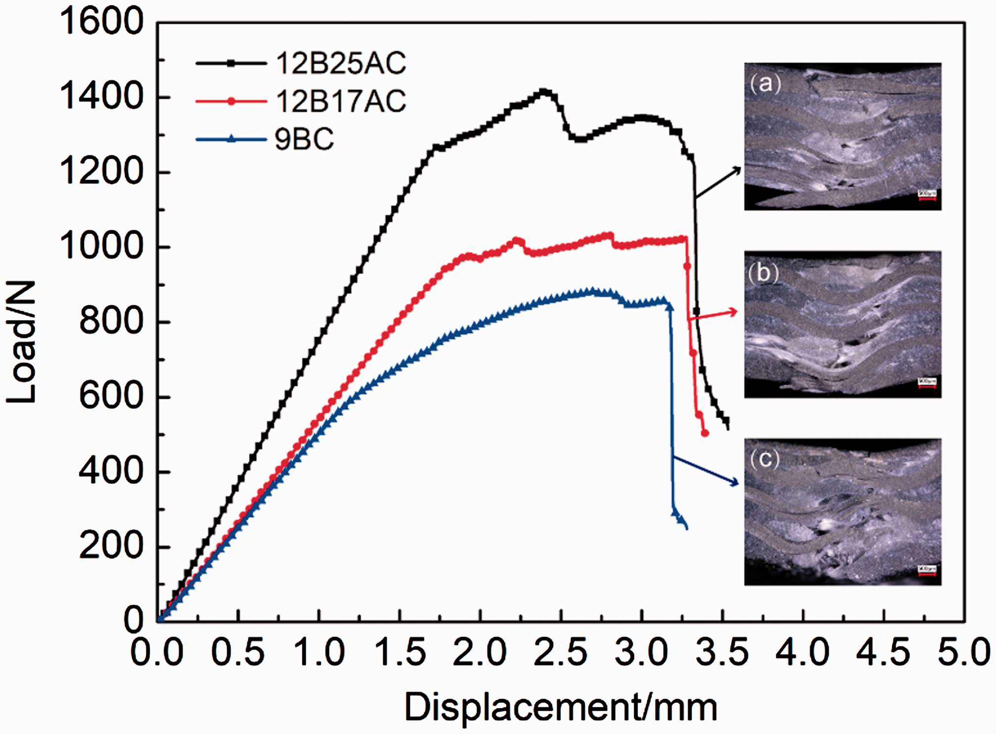
Figure 11 demonstrates the bending strength and modulus bar graphic of the three types of 2.5D composites. The bending modulus of 9BC and 12B17AC were the same, but the average bending strength of 12B17AC was 392.39 MPa, which was 12.2% higher than that of 9BC. This was because the core yarn of the flat core-spun yarn cannot be wrapped well by braided yarns (Figure 3(a)), resulting in friction loss in the core yarn during the manufactured process of composite. Moreover, the abrasion of core yarn led to a decrease in the overall bending property of 9BC.
Bending strength (a) and modulus (b) bar graphic of the three types of 2.5D composites.
The average bending strength and modulus of 12B25AC were 581.44 MPa and 52.08 GPa, which were 48.2% and 45.3% higher than those of 12B17AC (Figure 11), respectively. Those were aroused by the difference of the braiding angle of core-spun yarns. Comparing with 12B17A, the core yarn could be wrapped well by the braided yarns due to the large braiding angle in 12B25A. Hence, smaller bending degree presented in 12B25AC and the core fiber could better change its mechanical properties.
EM property
When EM wave incident into absorber, part of EM wave would be reflected from absorber surface owing to impedance mismatching between the absorber and free space, meanwhile, the other part of EM wave was consumed and converted into other types of energy, i.e. heat energy, and the residual EM wave transformed from absorber. Reflection loss (RL, in dB unit) is an effective parameter to evaluate the EM absorption performance of absorbent materials, which is the logarithmic scales of the ratio Er (electric field intensity of the reflected EM wave) and Ei (electric field intensity of the incident EM wave) as expressed by the following equation [9,17,34]

Figure 12 shows EM wave RL curves of three types of 2.5D composites in the frequency range of 8–18 GHz. In the whole testing range, the EM wave RL of the three types of 2.5D composites were below −3 dB. Liu et al. [35] reported that the RL of the T300 CF/epoxy unidirectional composites with 50% fiber volume fraction was from −1 dB to −2 dB in the frequency range of 8–18 GHz. By comparison, as-prepared composites exhibited better EM absorption properties than the unidirectional composites over a broadband frequency range of 8–18 GHz because of the mixed raw materials and the structural design of the composites.
EM wave RL curves of the three types of 2.5D composites.
Among the three RL curves, the 12B17AC and 12B25AC have a similar RL curve that the RL value increases gradually with the frequency increases. The maximum RL values of samples are −17.2 dB at 16.7 GHz of 12B25AC and −12.9 dB at 16.8 GHz of 12B17AC. The absorption bandwidth of below −10 dB for composites was 3.9 GHz (14.1–18 GHz) of 12B25AC and 2.8 GHz (15.2–18 GHz) of 12B17AC, respectively. When RL value is lower than −10 dB, it means that more than 90% of EM wave is consumed [36,37]. In other words, the 12B25AC and 12B17AC absorbed more than 90% of the incident EM radiation over a broadband frequency range of 14.1–18 GHz and 15.2–18 GHz, respectively. Hence, the 12B17AC and 12B25AC have better performance in EM absorption at high frequency band. But for 9BC, the RL curve fluctuates between −3 dB and −6 dB because the core yarn could not be wrapped completely by the braided yarns in the flat core-spun yarn (as shown in Figure 3(a)). In addition, a large amount of black CF can be seen on the surface of the preform (Figure 9(a)). Continuous CF is a strong reflector of EM waves due to its high degree of graphitization [13,14]. Therefore, incident EM wave directly reflected by the uncovering CF when the wave is incident on the surface of 9BC.
In addition, the EM wave reflection loss of 12B25AC was higher than that of 12B17AC, and this phenomenon was more obvious at high frequency. This was because the core yarn with large braiding angle could wrap the core yarn better, which is good for inducting EM wave into the interior of the material to consume. However, when the braiding angle was small, some core yarns were exposed during the preparation of the composite (Figures 8 and 9(b)), which is easy to form reflection on the EM wave. Therefore, the EM RL of 12B17AC was worse than that of 12B25AC.
At the same time, EM interference shielding effectiveness (EMI SE) of the three types of 2.5D composites also measured in the frequency range of 8–18 GHz. The value of EMI SE of a material indicates how much incident signal is blocked by the materials. A total of −20 dB EM ISE means 99% of incident radiation is blocked [38]. The total EMI SE (which is directly calculated from S-parameters) can be achieved as follows [39,40]

Figure 13 indicates the EMI SE of the three types of 2.5D composites in the 8–18 GHz frequency range. The EMI SE of 9BC is higher than that of 12B17AC, which is higher than that of 12B25AC, which is opposite to the RL because the EM wave was mostly reflected back in 9BC. Meanwhile, the total EMI SE of the three types of composites are all bigger than 20 dB in the whole testing range, which is the evidence that the three types of 2.5D composites are excellent shielding materials for EM interference. For commercial application purposes, the minimum EMI SE of a shielding material should be 20 dB [17]. From this point of view, the three types of 2.5D composites can meet the commercial requirements in the range of 8–18 GHz band.
EMI SE curves of the three types of 2.5D composites.
Conclusions
In order to meet the demands of both mechanical and stealth performance of weapon systems at the same time, three types of 2.5D CF/QF core-spun yarn/epoxy composites (described as 9BC, 12B17AC, and 12B25AC) were manufactured using three types of CF/QF hybrid core-spun yarns (described as 9B, 12B17A and 12B25A) have been successfully prepared. The mechanical test results indicated that 12B25A has better mechanical properties than those of 12B17A and 9B, and the 2.5D composite manufactured by 12B25A, 12B17A, and 9B have similar comparison. This is because the structure of 12B25A is round and the braiding angle is large. The EM wave absorption of 12B25AC less than −10 dB can cover 3.9 GHz (14.1–18 GHz) bandwidth and the maximum reflection loss (RL) values was −17.2 dB at 16.7 GHz, which were bigger than those of 12B17AC and 9BC. The EMI SE of the three types of 2.5D composite was measured to be larger than 20 dB at the frequency range of 8–18 GHz.
To sum up, the 2.5D composite made by round core-spun yarn with large braiding angle have better mechanical and EM properties. And 12B25AC was a structural absorbing composite with excellent mechanical properties and outstanding absorption capacity in the range of 14.1–18 GHz band. But the EM reflection loss of 12B25AC was not good in the range of 8–14.1 GHz, so we need to further adjustments the parameters of the core spun-yarn to make its composite absorb 90% EM energy over the entire frequency range (8–18 GHz) of radar.
Footnotes
Declaration of conflicting interests
The author(s) declared no potential conflicts of interest with respect to the research, authorship, and/or publication of this article.
Funding
The author(s) disclosed receipt of the following financial support for the research, authorship, and/or publication of this article: The authors acknowledge the financial support from National Natural Science Foundation, China (Grant No: 51603163), Science and Technology Project of Shaanxi, China (Grant No: 2017JQ5056, 2017JQ5054), Science and Technology Project of Textile Industry Association, China (Grant No: 2017041), Key Scientific Research Plan of Education Department of Shaanxi Provincial Government, China (Grant No: 18JS041), Young Talent fund of University Association for Science and Technology in Shaanxi Province, China (Grant No: 20160123), Thousand Talents Program of Shaanxi Province, and Sanqin Scholar Foundation of Shaanxi Province, China.