
Abstract
The demand for an efficient method for absorbing oil in harsh environments is increasingly urgent around the world. In this study, polyimide nanofibrous membranes were fabricated via electrospinning of polyamic acid precursor solutions followed by a thermal imidization. Polytetrafluoroethylene (PTFE) microparticles were added to modify the performance of polyimide nanofibrous membrane. Their morphologies were observed by field emission scanning electron microscopy, which revealed that polyimide nanofiber diameters ranged from 200 ± 20 to 350 ± 35 nm by adjusting polyamic acid concentrations. Polytetrafluoroethylene microparticles were embedded in polyimide matrices, which enhanced the mechanical strength and hydrophobicity of the polyimide nanofibrous membrane. Adding 1.8% polytetrafluoroethylene microparticles, the tensile strength of sample P6 was increased by 6.44-fold and water contact angles rose from 105 to 133°. Sample P2 had a maximum oil adsorption capacity of 2650% and a water contact angle of 107°, which might be considered a competitive future candidate for oil absorption at high temperatures.
Introduction
Oil spill accidents and industrial oil–water waste have been noted as a non-negligible factor in water pollution and have caused a series of damaging catastrophic events to aquatic animals and plants [1,2]. Due to efficiency and recyclability, absorbents used for oil spill cleanup are one of the most attractive techniques, which include porous fibers, non-woven fabrics, and aerogels [3–5].
Electrospun nanofibers have been widely used as excellent absorbents for treating environmental pollution, such as air and liquid filtration [6] and oil–water separation [3,7], due to their facile processing, high specific surface area, porosity, and good permeability. Many polymers, including polystyrene, cellulose triacetate, poly(vinyl alcohol), and polyamide, have been reported to fabricate nanofibers via electrospinning [8–11]. Nevertheless, their inherent nature does not allow them to be used in harsh environments, such as in high temperature (>200℃) and corrosive conditions. To overcome this problem, functional coating and nanofiller reinforcement have been reported to modify electrospun nanofiber properties [12,13]. On the other hand, electrospun nanofibers based on high-performance polymers, such as polyetherimide, polysulfone, and polytetrafluoroethylene (PTFE) [14–16], have been developed with inherently high thermal and chemical stability. Among these materials, polyimides (PIs) can be simply synthesized, have a wide usable temperature range (−196–450℃), excellent mechanical properties [17], and are currently a topic of great interest. Many studies have been reported regarding the applications of electrospun PI nanofibers, including in lithium-ion batteries [18], oil–water separation [7], and high-temperature exhaust gas filters [19]. Nevertheless, studies of PI nanofibrous membranes (NFMs) as oil absorbents have been few.
The aim of this study was to exploit an oil absorbent obtained by electrospinning, for use in harsh environments, especially high temperature. The oil adsorption capacity (OAC) of electrospun PI-NFMs were systematically evaluated with different oils and PTFE microparticles added to modify the properties of PI-NFMs. The effects of PTFE particles on tensile properties and wettability of porous PI-NFMs were investigated. The results suggested that PI-NFMs were potential candidates as absorbents for oil absorption, thus reducing secondary pollution and economic losses in harsh conditions.
Experimental and methods
Materials
Properties of the oils.

Preparation of PAA solutions and PAA/PTFE precursor suspensions
According to previous methods [17], polyamic acid (PAA), the precursor of PI, was synthesized by the polycondensation of PMDA and ODA. For this, ODA and DMF were first poured into a three-neck flask (250 ml) located in an ice bath (−2℃) with low-speed mechanical stirring (10 r/min). Then, an equivalent molar amount of PMDA was added to react with ODA for 8 h. Prepared at different concentrations (15, 18, and 21%), resulting PAA solutions were produced for electrospinning, denoted as the percentage of total mass of the two monomers and DMF volume (m/v).
Parameters of PI and PI/PTFE membranes.

ODA: 4,4′-oxydianiline; PMDA: pyromellitic dianhydride; DMF: N,N-dimethylformamide; PTFE: polytetrafluoroethylene; PAA: polyamic acid.
Preparation of PI and PI/PTFE-NFMs
Electrospinning was performed with a conductive needle having an inner diameter of 0.5 mm connected to a high voltage direct-current power supplier at ambient conditions (25℃ and 30% relative humidity, Figure 1). Feeding speed, receiving distance, and rotating drum speed were set as 0.6 ml/h, 13.5 cm, and 55 r/min, respectively, with the collecting time fixed for 6 h. Two different voltages (16 and 19 kV) were applied for spinning 18% PAA (Table 2), and the fabricated PAA nanofibers heated at 60℃ for 3 h to remove residual solvent.
Schematic showing the fabrication of PI nanofibrous membranes.
To obtain PI and PI/PTFE-NFMs, a thermal imidization was conducted. PAA and PAA/PTFE-NFMs were heated to 120 and 300℃ at a ramped temperature rate of 3℃/min, followed by annealing at each stage for 30 and 60 min, respectively.
Characterization
The morphologies of PI and PI/PTFE-NFMs were observed by field emission scanning electron microscopy (FE-SEM: S-4800, Hitachi Ltd, Tokyo, Japan). Prior to observation, samples were sputtered with gold, and the diameters of PI and PI/PTFE nanofibers measured using an image analyzer (Adobe Photoshop CS6).
Fourier transform infrared (FT-IR) spectra, collected using a Nicolet iS50 Fourier infrared spectrophotometer (Thermo Fisher Scientific Inc., Waltham, MA, USA) were used to characterize pure PI and PI/PTFE fibers in the range of 400–4000 cm−1 with a resolution greater than 0.09 cm−1.
NFM hydrophobicity was evaluated by measuring the static water contact angle (WCA) using a JY-82 contact angle tester (Chengde Precision Testing Machine Co., Hebei, China). The WCA was measured by dropping 3 μl of distilled water onto their surfaces. To obtain a reliable value, five WCAs were recorded at different areas for each sample and averaged.
The viscosities of polymer solutions and commercial oils were determined using a rotational viscometer (Kinexus, Malvern Instruments Ltd, Worcestershire, UK) at a 100 s−1 shear rate.
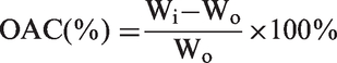
The OAC of NFMs was tested according to a previous report [20]. Weighed dry samples were immersed into an oil (sunflower, silicone, or lubricating oil) for 60 min according to the standard method F726-99 (ASTM). The oil-containing sample was then placed on a mesh with 10 mm openings for 10 min until oil droplets ceased to leak from the sample, and then the wet samples weighed. Specimens from each sample were examined in quintuplicate and OAC calculated using
Tensile properties of the NFMs were measured using a universal tensile testing machine (Instron 3369, Instron Corp., Norwood, MA, USA), with a load cell of 1 kN, tensile rate of 0.1 cm/min, and clamping distance of 20 mm. The tested specimens were cut into 40 × 8 mm2 rectangles and tested in quintuplicate.
The thickness of the prepared NFMs was measured using a digital thickness gauge (Chuan Lu 0–12.7, China). All tests were carried out at 20℃ and 60% relative humidity.
Results and discussion
FT-IR analysis
Imidization of PAA and PAA/PTFE was confirmed by FTIR spectra (Figure 2). The stretching vibrations of N–H bonds in amide groups and O–H bonds in carboxyl groups appeared in the region around 3000–4000 cm−1 in the PAA spectrum and disappeared after PAA imidization [21]. New bonds appearing at 1778 and 1722 cm−1 were ascribed to asymmetric and symmetric stretching of C=O bonds in imide rings and 1378 cm−1 generated by C–N bond stretching in imide rings [21]. All these changes in FTIR spectra indicated that PAA was effectively converted to PI after the thermal imidization process. Compared to the PI spectrum, no additional bands were observed in the spectra of sample P6, such that spectral comparison revealed that the presence of PTFE microparticles did not alter or shift transmittance peaks. This indicated that the microparticles were not involved in any chemical structure modifications in these PIs.
FT-IR spectra of PAA, PI, and PI/PTFE with 1.8% PTFE microparticle content.
Morphology
Representative FE-SEM images of the PI and PI/PTFE-NFMs were obtained under various concentrations and voltages (Figure 3), which revealed randomly oriented non-woven structures (Figure 3P1–3P6). Sample P1 (15% PAA) exhibited a regular and smooth cylindrical shape with a diameter of 220 ± 20 nm along the fiber axis. When the PAA concentration was from 18 to 21%, the corresponding P2 and P3 diameters increased from 265 ± 25 to 350 ± 35 nm (Figure 3(h)). These results were mainly ascribed to the increasing concentration and viscosity of the PAA solution (Table 2). Generally, a higher viscoelastic force contributed to larger diameters [9]. When the applied voltage was increased at 19 kV, the diameter of P2′ was 200 ± 20 nm. A higher voltage caused greater draft force for the polymer jet due to the greater columbic forces under a stronger electric field, which made fibers finer [9].
FE-SEM images of PI and PI/PTFE-NFMs: P1, P2, P2′, P3, P4, P5, and P6. (h) Fiber diameters of relevant NFMS.
Interestingly, “peach-shell-like” structures were observed in all prepared PI/PTFE-NFMs along the fiber axis (Figure 3P4–3P6). The appearance of “peach-shell-like” structures could be ascribed to PTFE microparticles surrounded by PI nanofibers, which were not involved in any chemical structure modifications in the present PIs (Figure 2). With the increasing PTFE particle content, the size of the “peach-shell-like” structure sizes became more regular and their numbers also arose. Comparison of sample P2 and PI/PTFE composite fibers showed that the diameters of sample P4 with “peach-shell-like” structures was 240 ± 35 nm when 0.45% PTFE particles were introduced. Increasing PTFE particles content to 1.8%, the fiber diameters were sharply reduced to 180 ± 30 nm. This result contributed to lower PAA/PTFE solution viscosity, which occurred via increased PTFE particle incorporation (Table 2), which favored solution stretching during electrospinning [9].
Contact angle
Wettability was evaluated by the WCA, as displayed in Figure 4. Generally, chemical composition and micro/nanostructure have great influence on material wettability [13,22]. Sample P1 had a WCA of 109°, showing good hydrophobicity due to its intrinsic functional group and fine diameter. And the WCAs of sample P2 and P3 decreased from 107 to 105° with increasing fiber diameter. Compared with sample P2, the WCA of P2′ increased to 112°, which was ascribed to its finer fibers. This indicated that fiber diameters played an important role in NFM hydrophobicity, whereas the smaller NFM nanofibers increased surface roughness and membrane hydrophobicity [13,22].
Static water contact angles of prepared PI and PI/PTFE-NFMs.
Compared with pure PI-NFMs, PI/PTFE-NFMs exhibited higher hydrophobicity. When 0.45% of PTFE microparticles were added, P4′ WCA increased to 125°, which was attributed to two reasons. On one hand, the surface of microsized “peach-shell-like” structures had many cupped pits providing more room for trapping air, which prevented water from contacting the solid surface. On the other hand, the finer diameter of PI/PTFE fibers connecting the “peach-shell-like” structures also optimized the composite NFM microstructures. When PTFE microparticle addition was 1.8%, P6 had the highest WCA of 133° because of increased “peach-shell-like” structures and rougher NFM surfaces, which acted as a “Lotus Effect” [23].
Oil absorption
Generally, electrospun NFMs composed of thin nanofibers had great specific surface areas and high porosities, allowing them to absorb more oils [24]. Pure PI-NFMs also showed good hydrophobicity and high porosity, yielding them excellent oil absorbents, as shown in Figure 5. When comparing pure PI samples with the same oil, P2 exhibited the greatest OAC, which was higher than samples with smaller nanofibers (P1 and P2′). These results explained why P2 with higher porosity provided large amounts of oil retention. And the OAC of P1 was higher than that of P2′. NFMs with the same spinning time were compactly stacked with thinner nanofibers and thus contained smaller voids and less room for oil retention. It was concluded that the more room between nanofibers played a crucial role in oil retention. These results were consistent with results from other studies [24]. During oil adsorption, oil molecules first adhered to the nanofiber surfaces via van der Waals forces and the larger surface area thus a benefit for oil adsorption. Then, free oil molecules were absorbed and stored in gaps between the fibers [24]. However, compared with other pure PI-NFMs, the OAC of P3 was the lowest, which was ascribed to low porosity and coarse fibers, which did not favor oil retention. Comparing the three oils, P2 also showed the highest OAC (2650%) for lubricating oil, which was ascribed to the relatively high oil viscosity increasing absorption, improving oil adherence onto fiber surfaces and keeping the absorbed oil stored in inter-nanofiber spaces. Therefore, the oil adsorption performance of P2 NFMs was a good and competitive result because of its specific surface area and void dimensions.
Oil absorption capacity of PI and all PI/PTFE-NFMs.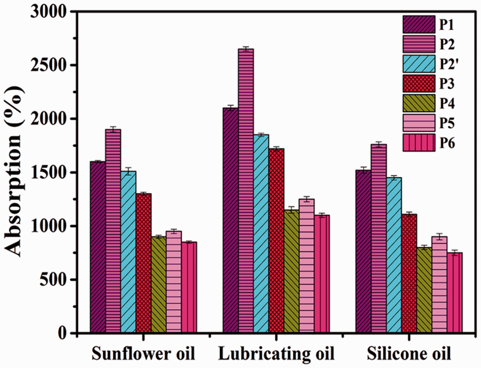
When PTFE microparticles were added, the OAC of composite NFMs significantly decreased. With 0.45% PTFE microparticle addition, the maximum OAC of P4 NFMs was 1150% for lubricating oil among the three oils. This might have been due to the lower porosity of the PI/PTFE-NFMs because of PTFE introduction. In addition, P5 showed the highest oil absorption capacity (1310%) among the hybrid NFMs. There results could have been due to synergy effect of large nanofiber surface area and porosity between the hybrid fibers. In addition, all samples showed the highest adsorption capacity for lubricating oil due to its viscosity.
Mechanical properties
The relation between stress and strain values of P1 and PI/PTFE-NFMs and their tensile properties are shown in Figure 6 and listed in Table 3. Higher spinning solution concentrations produced larger molecular weights of synthesized PAA, which would improve the tensile properties of the corresponding PI-NFMs. However, P2 spun from 18% PAA had the highest tensile strength at 2.91 MPa. This depended upon interfiber entanglement and increased fiber stretching ability [25].
Tensile stress–strain curves of PI and PI/PTFE-NFMs. The tensile properties of PI and PI/PTFE-NFMs.

With PTFE microparticle addition, the tensile modulus and strength of these fibers were significantly increased. The presence of 1.8% PTFE particles yielded the strength and modulus of P6 to be 6.44 and 58 times higher than those of P2, respectively (Table 3). This was due to the reinforcement role of PTFE particles, which bonded NFM nanofibers (Figure 3P4–3P6), and improved stability by great improvement of membrane crystalline degrees [25,26].
Conclusions
In summary, PI and PI/PTFE-NFMs were fabricated via electrospinning. PTFE particles had significant effects on the morphology and mechanical properties of PI/PTFE-NFMs. Both the mechanical property and hydrophobicity increased with PTFE particle content. By adding 1.8% PTFE particles, the tensile strength was increased by 6.44 times and WCA significantly increased from 105 to 133°. Sample P2 with 18% PAA exhibited the best OAC for the three oils among the other samples, and the OAC reached to 2650% for lubricating oil due to its smaller fibers and higher porosity. P2 had good hydrophobicity of 107° and was suitable for oil absorption in harsh environments. Moreover, the OAC of the pure PI-NFMs could be controlled by changing processing parameters and solution properties. It was believed here that the prepared PI-NFMs had potential applications for oil absorption and greatly reduced economic losses at high temperatures.
Footnotes
Declaration of conflicting interests
The author(s) declared no potential conflicts of interest with respect to the research, authorship, and/or publication of this article.
Funding
The author(s) disclosed receipt of the following financial support for the research, authorship, and/or publication of this article: This study was financially supported by the National Natural Science Foundation of China (Grant No. UU1607117) and the Application Foundation and Advanced Technology Research Plan of Tianjin (Project Nos. 16JCZDJC36400 and 15JCZDJC38500).