
Abstract
This paper attempts to show the effect of silica nanoparticles and polyethylene glycol mixture (shear thickening fluids) on tensile and flexural properties (3-point bending) of glass and carbon fibre-reinforced thermoset composite laminates. The shear thickening fluids were prepared by combination of silica nanoparticles and polyethylene glycol using various silica contents (10–20 wt%). A viscometer was used to evaluate the shear thickening characteristics and viscosity of shear thickening fluids increased by increasing the silica content. Shear thickening fluids were impregnated on the host of glass and carbon fabrics and subsequently converted to composite laminates using vacuum infusion method with an epoxy matrix. It was found that shear thickening fluids-treated carbon and glass fabric composites exhibited up to 10% and 12% higher tensile strength than neat composites whilst the tensile modulus increased about 24%. Shear thickening fluids-treated fabric composites exhibited slower damage propagation compared to brittle nature of untreated fabric composites. However, lower flexural strength with higher energy absorption (up to 27%) were obtained after using shear thickening fluids for both carbon and glass fibre composites.
Introduction
Fibre-reinforced polymer laminate composites are widely used in aerospace, automobile, military and energy applications. Their high strength and stiffness to weight ratios are their main advantages over metallic structures. However, their low impact tolerance, easy delamination and poor damage tolerance behaviours are the main disadvantages [1,2]. Induced damage can significantly reduce the compressive strength as well as damage tolerance of the structure after low and high velocity impacts [3,4]. There are different methods for improving impact resistance and residual strength of the composite laminates, such as modifying the resin system, using thermoplastic matrices, using 3D textile preforms or introducing through thickness reinforcement [5–7].
There is an increasing trend to use shear thickening fluid (STF) to enhance ballistic and impact properties of high performance fabrics [8,9]. STF solutions are non-Newtonian fluids as their viscosity increases with increasing shear rate above reaching a critical shear rate [10,11]. Lu et al. [12] investigated compressive and impact behaviour of warp-knitted spacer fabrics impregnated with colloidal STF. They observed that viscosity of STF increased with shear rate and they are potential materials for personal protection. Decker et al. [13] observed better stabbing resistance for Kevlar and nylon fabric after treating them with STF. They claimed that colloidal silica particles provided coupling between STF and fibres, and hence more efficient load transfers were achieved. Park et al. [14] experimented that STF impregnation increased energy absorption of Kevlar fabrics up to 70% enhanced compared to neat Kevlar fabric. Hassan et al. [15] observed that STF/Kevlar fabrics exhibited better stab resistance and bearing loads compared to that of Kevlar without STF, and fabric flexibility highly affected after using STF. Majumdar et al. [16] prepared STF solutions containing various amount of silica particles (50–70% wt). They claimed that shear thickening increases with increasing silica content and absorbed energy not only depended on the silica content, but also processing parameter. Tan et al. [17] prepared twaron fabrics containing 0, 20, 40 and 50 wt% STF and observed that ballistic limits of Twaron fabrics increased between 0% and 40% silica content, whilst it decreased beyond this level. He et al. [18] investigated the influence of the STF on impact performance of STF/Kevlar fabrics. Their results showed that using STF enhanced impact resistance force, deformation displacement and energy absorption.
STF also increases friction coefficients of textile yarns and fabrics [19] whilst higher energy can be absorbed when the friction between yarns increased [20]. Silica particles may behave as sizing on the surface of the yarns and increase the surface roughness which contributes the interfacial bonding between matrix and fibre parts [21]. Previous researches have also established that thermoset polymers can be toughened using silica nanoparticles [22,23]. Sprenger et al. [24] attempted to reinforce the matrix part of the carbon/epoxy composites (CCs) using silica nanoparticles. They observed reduction in compression after impact due to agglomeration of silica particles.
The literature mostly focused on enhancing mechanical properties of fabrics or polymers [25,26] using STF or silica particles [27]. However, there is little published data on investigating composite laminates containing STF-impregnated fabrics [28]. Neagu et al. [29] attempted to improve damping characteristic of glass/epoxy composites (GCs) using STF by building a high shear–strain interface. Recently, a considerable literature has grown up around investigation of impact and ballistic performance of STF impregnated fabrics. However, there have been few investigations on the tensile properties of STF-treated fabrics [30]. In addition, the research to date has tended to focus on impregnating aramid [31–33] or thermoplastic fibre [34,35] fabrics rather than glass and carbon fibre fabrics. Much uncertainty still exists about the effect of STF-treated fabrics on mechanical properties of thermoset composites. Extensive research has shown that modifying matrix parts using silica particles enhanced mechanical properties of composite laminates. However, research to date has not yet determined tensile behaviour of silica nanoparticle-treated glass or carbon fabric composites. Therefore, this work aims to investigate the effect of silica nanoparticles, PEG, and their combination (non-Newtonian fluids) on the host of glass and carbon fabrics composites (glass/epoxy and carbon/epoxy). This study seeks to obtain data which will help to address these research gaps mentioned above by examining the flexural and tensile behaviour of GC and CC containing STF-treated fabrics.
Experimental
Materials
Silica nanoparticles (Aerosel 200) with 12 nm particle size were supplied from Marmara Ecza [36] and it is a colloidal hydrophilic fumed silica. Polyethylene glycol (PEG 400) and ethanol were purchased from Tekkim [37]. The 2/2 twill glass woven (280 g/m2) and 2/2 twill carbon woven (245 g/m2) fabrics were obtained from DostKimya. Warp and weft density of both fabrics are 6/cm and their yarns counts are 200 Tex.
Preparation of STFs
STFs were prepared by dispersing silica nanoparticles and PEG with various silica content (10%, 15%, and 20% wt; Figure 1(a)). The solution was homogenised using a mechanical mixer at 2000 r/min speed for an hour (Figure 1(b)), and subsequently processed at an ultrasonic bath for 30 min to obtain a homogeneous solution for the shear thickening effect at room temperature. Figure 1(c) presents the STF which is a colloidal suspension.
Manufacturing of glass and carbon fabric composites containing STF.
Preparation of STF-fabrics and composites
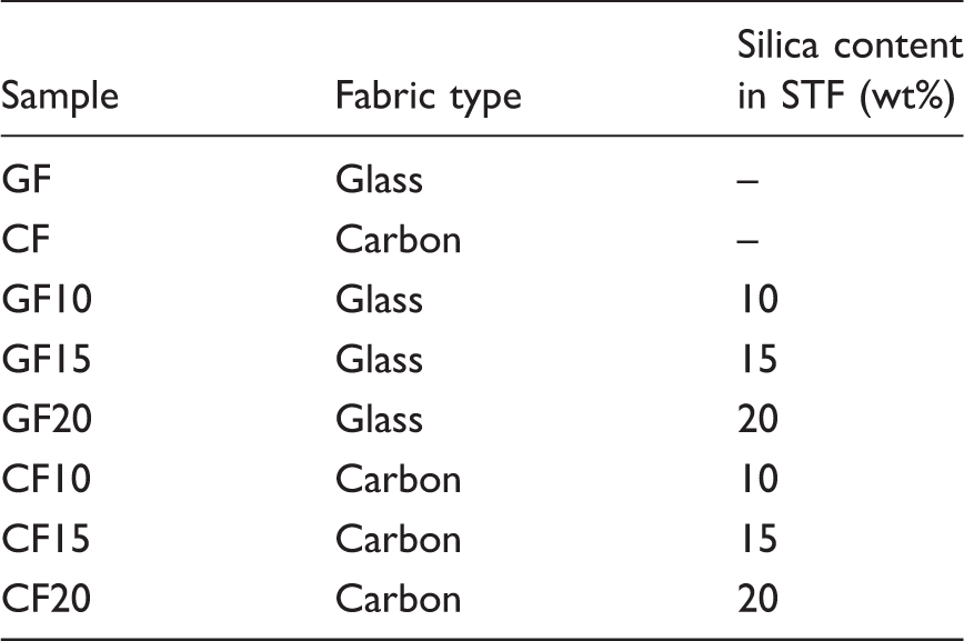
Fabric samples.
Test methods
Viscosity measurements
Viscosity of STF was performed with a Brookfield-DV2TRV viscometer using the RV-6 spindle between different rotational speeds (5–200 r/min) to obtain different shear rates.
Fabric tensile and friction tests
Fabric tensile tests were performed using a Hounsfield H5KS test machine at 100 mm/min constant displacement according to BS EN ISO 13934-1 standard. Dynamic (μD) and static (μS) coefficient of frictions were calculated using ASTM D1894-01 standard at a constant displacement of a polished metal sled (200 g) at 150 mm/min (Figure 2). The test software (QMAT Testzone) automatically calculated the coefficient values using equation (1). Where AS is the initial motion scale reading (g); B, weight of sled (g); AK, average scale reading obtained during uniform sliding of the material (g)
Fabric friction test.

Composite density and volume fraction tests
Density and volume fraction of glass composites were measured using ASTM D792-08 and BS ENISO 1172:1999 test standards. However, volume fraction of CCs was calculated theoretically as equation (2) due to burning problem of carbon fibre during the measurement


Composite samples with different silica content.

Composite mechanical tests
Flexural behaviour (3-point bending) of the composite laminates was evaluated according to ASTM D7264 standard using a Hounsfield H5KS test machine at the cross-head speed of 5 mm/min. Composite tensile tests were carried out on a Zwick Roell/Z100 testing machine according to the ASTM D3039 standard at a crosshead speed of 2 mm/min. The size of the composite tensile tests specimens was 150 mm × 25 mm. Zeiss-EVO LS10 scanning electron microscope (SEM) was used to evaluate the surface morphology of fabrics and failure types of composites laminates at 30 kV voltage.
Results and discussions
Rheological properties of the STF
The viscosity of STF with different silica content is shown in Figure 3 as a function of shear rate (r/min). The viscometer that is used for this study is not capable of measuring shear rate and stress. However, another factor which is rotational speed of the viscometer spindle also indicates the shear rate whilst shear rate increases with increasing the spindle speed (r/min). Thus, shear thickening behaviour of the fluids was presented as viscosity/speed plot. Figure 3 shows that the initial viscosity values increase with increasing silica content for STF solutions. Experimental results showed that the solution did not show thickening behaviour under 10% silica contents, thus the minimum amount was kept as 10% for this study. The STF solutions exhibit both shear thinning and shear thickening behaviour. The STF solutions show shear thinning behaviour until 175–180 r/min whilst the viscosity decreases sharply by increasing the shear rate. Beyond this critical level, the viscosity of all fluids increase, hence they start to show shear thickening behaviour. The reason may be that silica particles form hydro-clusters when a sudden stress is applied through higher rotational speed. It can also be seen that STF with higher silica content (20%) exhibits shear thickening behaviour at lower rotations per minute than that of 15% and 10% silica loadings. This can be explained by the fact that the more silica nanoparticles the greater the interaction will occur between nanoparticles within the matrix. This greater interaction between particles causes more complicated movement during flow, resulting in changing viscoelastic properties as can be also seen for graphene nanoplates inclusion to epoxy matrix [39].
Shear thickening behaviour of STF with different weight ratios at different speeds (r/min). STF absorption for: (a) carbon and (b) glass fabrics at different silica content.

Fabric test results
Figure 4 presents STF absorption ratios of carbon and GFs at different soaking times after removal of the ethanol. It can be seen that the amount of STF absorption increases with increasing silica content for both fabrics. However, carbon fabrics absorbed more STF than GF at all soaking times. It is interesting that no significant correlation was found between soaking time and STF absorption. Therefore, fabrics were soaked only for 1 min in the solution for the impregnation of STF/carbon and STF/GFs as discussed in experimental section.
Figure 5 presents dynamic and static friction coefficients of carbon and GF containing different amount of silica nanoparticles. It can be seen that both dynamic and static coefficient values increase with increasing silica content. Carbon fabrics showed higher coefficient than that of GFs, which is obviously due to the higher amount of STF absorption as seen in Figure 4 and inherent surface roughness of carbon fabrics. Figure 6 indicates the force required to move the metal sled over the glass and carbon fabrics. It can be seen that STF-impregnated fabrics had higher force than neat fabrics, and force values increase with increasing amount of silica particles. This enhancement in surface friction may help to improve the energy absorption of fabrics and composite laminates.
Dynamic and static friction coefficient of glass and carbon fabrics at different silica contents. Surface friction behaviour of: (a) glass and (b) carbon fabrics with different STF ratios.

Figures 7 and 8 show SEM images of STF-treated carbon and GFs at different silica ratios. It can be seen that there is a good STF dispersion over the fabrics and the amount of STF on fabrics increases with increasing silica content for both fabrics. This is one of the other reasons to have higher dynamic and static friction values by increasing silica contents as shown in Figures 5. Figures 7 and 8 indicate that the distribution of STF on carbon fabrics is more homogeneous than that of GFs, and most of the fibres were covered with STF. This result may be explained by the fact that carbon fabrics absorbed more STF than GFs (Figure 4), resulting in better STF holding on the carbon fabrics compared to the GFs during the hanging process as explained in experimental part. Hence, some ununiform or untreated regions were formed after the soaking process for GFs. There are some untreated regions on the GFs at higher silica contents (Figure 8(c),(d)). For the highest ratio (Figure 7(d) and Figure 8(d)), STF forms a thin layer on the fabric surfaces which may directly affect the composite properties. These thin layers make the sled obstacles more at higher silica ratios and higher force values are needed to move it over the fabrics as shown in Figure 6.
SEM images of carbon fabrics: (a) 0%, (b) 10%, (c) 15% and (d) 20% silica contents. SEM images of glass fabrics: (a) 0%, (b) 10%, (c) 15% and (d) 20% silica content.
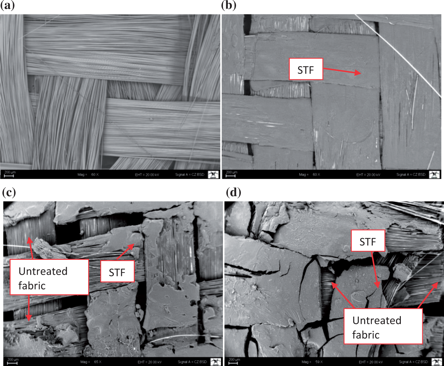
Figure 9 presents force-extension behaviour of glass and carbon fabrics before and after the STF treatments. It can be seen from Figure 9 that breaking forces of carbon and GFs did not change with increasing STF contents. Similar results were observed on aramid fabrics impregnated with STF by Na et al. [30]. This might be due to addition of STF only affected the surface properties of fabrics rather than deteriorating or enhancing chemical structure of carbon and glass fibres. However, addition of STF decreased maximum extension values of carbon fabrics as seen in Figure 9(a) whilst their extensions at maximum break values are very similar. On the other hand, pure GF had slightly lower maximum extension values than that of STF-treated fabrics. These factors may explain that there is not a relatively good correlation between fabric tensile strength and STF addition. Figure 9(a) also presents that carbon fabrics have very similar breaking force behaviour until 5 mm extension values, indicating their stiffness are very identical to their strength values. Similar results can be seen for GFs in Figure 9(b).
Breaking forces/extension plots of (a) carbon and (b) glass fabrics at different silica ratios.
Composite test results
Table 2 presents CC and GCs that contain STF-treated carbon and GFs in addition to only silica and PEG-treated GF composites (GSI and GPEG). It can be seen from Table 2 that the thickness of the laminates increased by addition of STF, which is due to embedding of STF on the fabrics creates thin layers on the fabrics as shown in Figures 7 and 8. As can be seen from these figures, there are more amounts of STF on the fabrics as the STF ratio increases. The density of STF-reinforced glass and carbon composites is slightly lower than their neat GC and CC composites. Comparing fibre volume fraction, GC composite had the lowest fibre volume fraction compared to STF-treated composites. It seems possible that these results are due to density of STF solution is between 1.23 and 1.34 g/cm3 depending on the STF ratio, whilst the densities of silica nanoparticles and PEG are 2.2 and 1.12 g/cm3, respectively, according to the suppliers. In contrast to glass composites, both density and fibre volume fraction of composites decreased by addition of STF for carbon composites. This inconsistency may be due to increment of composite thickness for carbon-based composites after STF absorption.
Table 3 and Figure 10 present tensile test results of STF-treated glass and carbon fabric composites. What stands out in the table is tensile strength of glass and carbon composite laminates slightly increased after using 10% and 15% STF-treated fabrics. It can be seen that the tensile strength of GC increased by 6% and 12% after using 10% and 15% STF, respectively. For CCs, the increase was about 5% and 10%. A possible explanation for this might be that obtaining higher surface frictions for carbon and GFs (Figure 5 and 6) decreased yarn mobility which leads to increase the energy to pull-out the yarns during tensile loading [40]. Hence, higher tensile loads and strength achieved for CC10, CC15, GC10 and GC15 composites due to better stress transfer between the fabrics. However, beyond this level, tensile strength of all carbon and glass composites decreased sharply. This result can be explained by the fact that STF created a thin layer on the 20% STF-treated fabrics as observed in Figures 7 and 8, hence the interfacial bonding between fibres and matrix decreased compared to 10% and 15% STF-treated fabrics, resulting in lower stiffness and early failures. This shows that silica content should not exceed over 15% to avoid reduction in tensile strength of composite laminates. Table 3 indicates that the tensile modulus of glass composites increased about 16% and 24% after using 10% and 15% silica loading, respectively. However, tensile modulus decreased about 5% for 20% silica loading. For carbon composites, CC10 and CC15 composites exhibited about 11% and 24% higher tensile modulus than untreated carbon composite, respectively. On the other hand, 20% silica-treated carbon fabric composite showed about three times lower tensile modulus than that of untreated carbon fabric composite. Tensile test results indicated that non-Newtonian fluids could not show shear thickening behaviour due to static tensile loading. However, they contributed to surface friction of composite preforms, hence the tensile strength and modulus values were improved for 10% and 15% silica loading. Table 2 presents that samples with STF-treated fabrics had higher void content than pure glass and carbon composites. It is clear that 20% silica loading led to higher void content compared to 10% and 15% silica loadings. These higher void contents can also reduce the tensile strength of composites due to creating weaker and failure propagation points under loading.
Stress–strain behaviour of carbon and glass fabric composites. Tensile test results of glass and carbon fibre composites with various STF.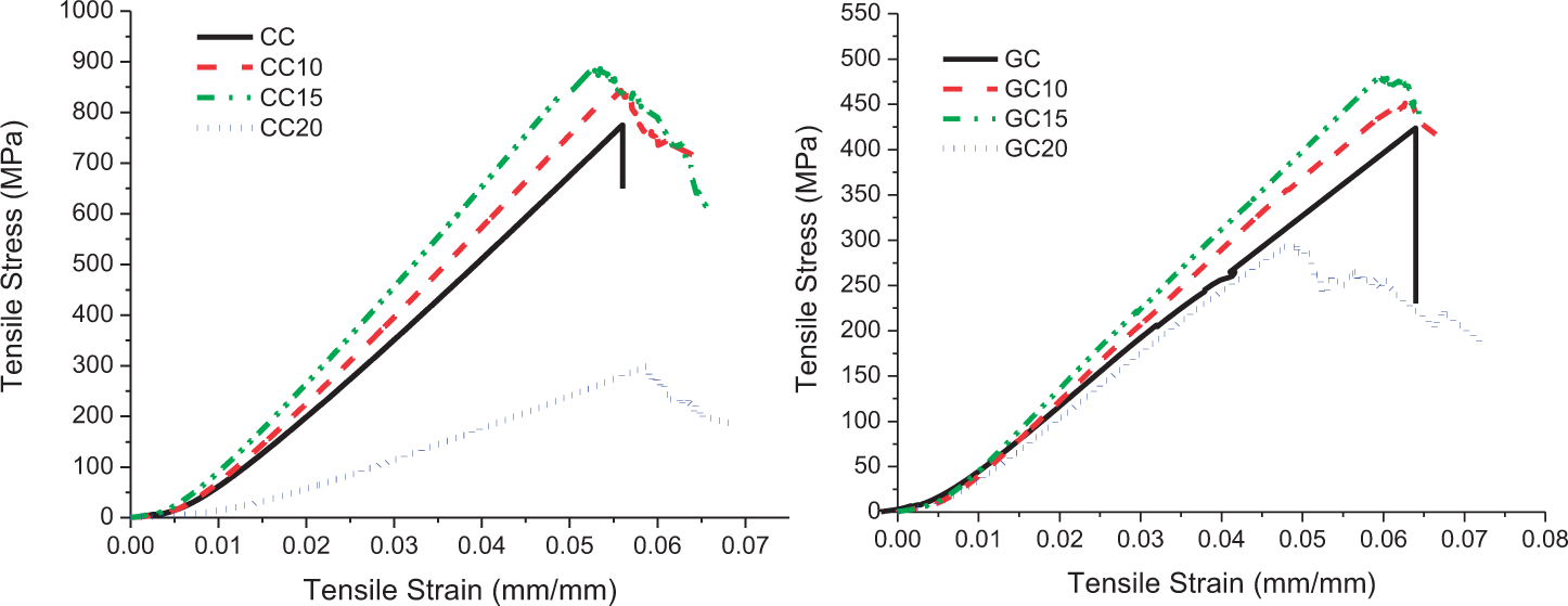
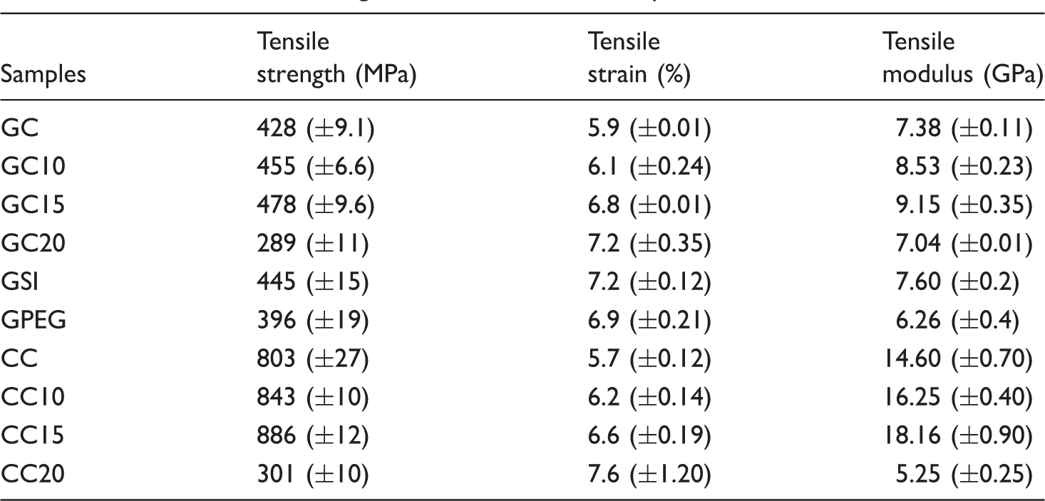
Figure 11 presents fibre failures during tensile loading for GC20 and CC20 samples. STF coating on glass and carbon fibres can be clearly seen and this leads to poor stress transfer between fibres and matrix due to the weak bonding which is the reason for obtaining lower tensile strength for 20% STF-treated composites. It might be expected that increasing fabric surface friction (Figure 5 and 6) enhances the tensile properties of GC20 and CC20 laminates as observed for other laminates (GC10, GC15, CC10 and CC15). However, interfacial bonding becomes more predominant than surface friction for higher silica ratios (20%), since the weak bonding led to early failures. It is interesting to note that composites with 20% silica content showed higher extension than the composite laminates containing 10% and 15% as shown in Table 3. This increase in extension to failure leads to increase in ductility of 20% silica-treated composite laminate.
SEM images of fibre failures during tensile loading for: (a) GC20 and (b) CC20 composite samples.
Figure 12 presents the failure modes of composite laminates. As shown in figure, CC and GC laminates failed with lateral middle failures, and specimens completely fractured as two pieces. However, STF-treated samples had different failure modes such as angled middle failure (CC10 and GC10), long-splitting middle failure (CC15 and GC15) and edge delamination (CC20 and GC20). It was observed that neat samples showed sudden fracture and breakages during testing whilst STF-treated samples exhibited damage propagation and the failures/fractures occurred slower than the neat samples. These failure behaviours can be also clearly seen in Figure 10 that untreated carbon and glass composites exhibited sharp decreases in stress values whilst all STF-treated fabric composites had damage propagations (Figure 12) and failed with more ductile behaviour. The observed change in failure mechanism could be attributed to fabric/matrix debonding due to lower interfacial bonding between fibres and matrix after using STF. The energy was stored at the weak interfaces rather than fracturing the fibres, and hence STF-treated fabric composites failed with slower fractures compared to untreated fabric composites.
Test specimens after tensile loading.
Table 3 and Figure 13 also present that composites with only containing silica nanoparticles (GSI) and PEG (GPEG) had lower tensile strength than their combination (GC15). Silica nanoparticles and PEG remained on the fabrics as powder and liquid forms, respectively; hence they could not create a strong interfacial bonding to transfer the load as good as STFs which are their combinations. This shows that using silica nanoparticles and PEG together shows a synergic effect to enhance tensile strength of composite laminates due to formation of STFs. Figure 13 also shows that GSI sample fails with a sharp decrease compared to ductile failure of GPEG sample as observed in Figure 12, indicating that silica nanoparticles and PEG contribute strength and ductility of composites, respectively.
Stress–strain history of GC15, GPEG, and GSI composite laminates.
Table 4 and Figure 14 present three-point bending test results of STF-treated carbon and GF composites at different silica contents. Flexural stress (σ) and strain Stress-extension curves of glass and carbon composites. Flexural properties of glass and carbon fibre composites with various STF.


Table 4 and Figure 14 exhibit that flexural strength of GC decreased from 572 to 132 MPa, 125 and 41 MPa after using 10%, 15% and 20% silica content in STF, respectively. Similar results were observed for CC whilst flexural strength of CC decreased with increasing silica content. This shows that the addition of STF on carbon and GFs did not improve the flexural strength of composite laminates in contrast to enhancement of tensile properties except at 20% silica loading. This discrepancy could be attributed to loading conditions of testing, since composites are more prone to delaminate at flexural loading compared to axial loading as for tensile test when the interfacial bonding is slightly weak. Table 4 also indicates that STF-treated fabric composites had lower flexural modules than pure carbon and glass composites.
Load-extension curves of glass and carbon composites (except GC and CC).
Figure 14 indicates that STF-treated composite samples failed at higher extension values compared to their neat composites. For instance, flexural strain of the neat glass composite is 4.8 whilst STF-treated composites exhibited up to 21.90 strain values as presented in Table 4. Figure 15 presents the three points (A, B, and C) that show the deformation history of samples on a typical load-extension curve for STF-treated fabric composites. Neat composites were not presented in Figure 15 to obtain clearer failure curves. All samples show linear elastic behaviour up to point-A with different stiffness values (Figure 15). After getting over point-A, stiffness of neat composites (GC and CC) was reduced significantly, and they rapidly failed. However, there are slight decreases for STF-treated composites after point-A, and the load carrying capacity almost kept same until point-B with a large plastic deformation. Finally, they failed at point-C with a relatively low flexural load. This shows that, the load carrying capability of STF-treated composites reduced with a relatively gentle rate and failed with a ductile manner compared to brittle neat composites. Figure 15 also presents that some of the samples had fluctuations between A and B such as GC10 and CC10 samples. It seems possible that this is due to toughening effect through enhancing ductility of the composites in which structure is still able to carry the flexural loads although the first failure happens. The energy absorption during flexural loading was also calculated by integrating the load-extension curves (Figure 15) using Originlab software and presented in Table 4. The average energy absorption of GC composite was 1006 mJ, and 21% and 18% increase were observed after using 10% and 15% silica contents, respectively. However, using 20% silica content decreased the energy absorption capacity by about 27% compared to GC composite. For CC composite, using 10% and 15% increased the energy absorption capacity whilst it decreased about 70% after using 20% compared to CC composite. Weak interfacial bonding between STF-treated fabrics and matrix generally leads to higher energy absorption due to fibre debonding and pull-out [41]. However, beyond 15% silica contents, very low flexural strength and energy absorption values were achieved for this study. This shows that the silica content must not exceed over 15% in order to avoid undesirable results for composite laminates.
Figures 16 and 17 present the fracture mechanism of composite laminates after three-point bending tests. It can be seen from Figure 16(a) that the neat composite mainly fails with fibre fracture and matrix cracks during flexural loading. However, an additional failure mechanism which is delamination takes place in addition to fibre breakage and cracks after using STF due to weak interfacial bonding. Higher delaminated regions were observed when the silica content increased as in Figure 16(d), and composite samples start to fail with delamination rather than fibre breakages. It seems that less amount of force is needed to create delamination or fabric/matrix debonding compared to fibre breakages as mainly observed for the neat GC. Figure 17 presents failure mechanism of carbon fibre-reinforced composites at different silica content. Similar failure mechanism can be observed as glass composites; however, higher delamination occurred as shown in Figure 17(c) and (d). The observed increase in delamination for carbon composites is probably due to higher amount STF absorption (Figure 4) and formation (Figure 7) on the surface of carbon fabrics. It is also clear that fibre splitting indicates the weak interfacial bonding between STF-treated fabrics and epoxy resin at high silica loadings.
Flexural failure of glass/epoxy composites with: (a) neat, (b) 10%, (c) 15% and (d) 20% silica contents. Flexural failure of carbon/epoxy composites with: (a) neat, (b) 10%, (c) 15% and (d) 20% silica contents.

Conclusions
Flexural and tensile properties of STF-impregnated carbon and glass fibre composites were investigated. Viscometer results indicated that STF showed thickening characteristic when silica contents were kept between 10 and 20 wt% in a colloid dispersion. The following conclusions can be drawn from the present study:
Fabric tensile results showed that addition of STF did not significantly change the strength of carbon fabrics. However, friction test results indicated that STF-impregnated fabrics had higher dynamic and static friction than that of plain carbon and GFs. The STF distribution over carbon fabrics was slightly better than GFs. Composite tensile test results showed that 10% and 15% STF addition increased the tensile strength of composite laminates due to increasing surface friction of carbon and GFs. However, this was opposite after using 20% STF inclusion which is due to weaker bonding between fibres and epoxy matrix. This discrepancy could be attributed to reaching a threshold point for fibres and matrix bonding at 20% silica content, resulting in reversible effect on mechanical properties of composite laminates. Composite tensile results showed that using silica nanoparticles and PEG together exhibited higher tensile strength values when they were used individually as silica nanoparticles and PEG. Three-point bending results showed that flexural strength of glass and carbon fibre composite laminates decreased by addition of STF. However, they exhibited higher extension at break values and energy absorption compared to neat composites. Addition of STF changed failure mechanism of composite laminates by enhancing the ductility of the structures. The aim of the present research was to examine the STF-treated fabric composites and to observe whether they show shear thickening characteristic when they are used in thermoset polymer matrix composites. It was seen that they did not show silica hydro-clusters and shear thickening behaviour, this may be due to applying of static loads (tensile and flexural) rather than dynamic load and formation of epoxy thermoset matrix surrounding over and through STF. However, inclusion of STF contributed to tensile strength of composites laminates through increasing the dynamic and static surface friction of composite preforms. These tensile and flexural tests’ results may serve as a base for the future studies which is to evaluate the impact damage tolerance of STF-treated fabric composites. These STF-treated fabric composites can be used where the high ductility and strength are required as automotive and aerospace applications.
Footnotes
Acknowledgements
The author acknowledges to graduate students Yunus Tepebaşılı and Yıldırım Çiftçi for their assistance during manufacturing of composites.
Declaration of conflicting interests
The author declared no potential conflicts of interest with respect to the research, authorship, and/or publication of this article.
Funding
The author(s) disclosed receipt of the following financial support for the research, authorship, and/or publication of this article: This study was supported by The Scientific and Technological Research Council of Turkey (TUBITAK) under the project number of 216M281.