
Abstract
The process of integrating smart materials into fiber-reinforced plastics has been used increasingly to create different high-performance products for lightweight applications. This paper presents the development of an adaptive morphing wing based on fiber-reinforced plastics with shape memory alloys integrated into the reinforcing fabrics. Two types of preforms with varying numbers of integrated weft yarns in shape memory alloys were manufactured for a wing structure on a weaving machine using the pleated woven fabric technology. Subsequently, the realized preforms were infiltrated by a thermoset matrix and characterized mechanically to derive a preferred variant. After developing the adaptive morphing wing, its deformation behavior was characterized by varying current flow and time through shape memory alloys. Results revealed that maximum deformation of the investigated adaptive morphing wing was achieved at a current flow and time of 1 A and 60 s, respectively.
Keywords
Introduction
Morphing has been widely used in the aeronautics sector; the term itself refers to a component that changes its shape depending on environmental conditions [1]. The morphing flight-vehicle experimental (MFX-1) [2], unmanned aircrafts, and the variable gull-wing morphing aircraft [3] are just a few examples of morphing aircrafts. The most common applications for morphing wings in the aeronautics industry are the smart trailing edge, smart winglet, smart slat, and smart drop nose [4]. Actuated morphing wings are also used in bat-like micro aerial vehicles [5] or as leading edges, engine inlets, helicopter rotor blades, ships, wind turbines, hydrodynamic surfaces, and automobiles [6,7].
The aerodynamic behavior of shape morphing wings can be changed by planform alternation, out-of-plane transformation, or airfoil profile adjustment [8]. Considering active materials suitable for use in shape morphing wings, several conceptual approaches are available in scientific literature [1,8]. Shape memory alloys (SMAs) and piezoelectric materials are promising actuator materials for morphing structures [9]. Although piezoelectric materials can be used as morphing skins for small unmanned aircrafts and adaptive trailing edge devices on wind turbine blades, they contain lower blocking forces and less strain resistance compared to SMAs [6,10]. Moreover, they are commonly available in the form of thin sheets. In contrast to the subject matter addressed above, SMAs have a variety of specific advantages, i.e. they have very large usable specific energy densities (2 × 10³ J/kg) and reproducible deformation patterns for movement cycles well above 105 [11,12]. They are commercially available in wire form and thus, in principle, suitable for textile processing. Furthermore, SMAs possess a very high actuation force and can act as sensor [6,13].
Due to their light weight, superior mechanical properties, anti-corrosion properties, reduced tooling costs, higher energy absorption capability as well as better damping properties compared to metallic materials, fiber-reinforced plastics (FRPs) offer great potential for the production of morphing structures [14–17].
Very few studies have so far explored the options for the development of adaptive morphing wings produced by means of SMAs and FRPs [4,18–20]. In the case of the German Aerospace Center (DLR) developed “morphing wing” [4,20], SMAs and glass fiber-reinforced elastomers were used; these SMAs served only as passive deformable kinematics by exploiting their superelastic effect. A major disadvantage of these studies is that they do not address the force transmission from actuator to reinforcing fabrics since the actuators are placed in the skin of the morphing wing. However, a breakthrough in terms of higher force transmission from actuator to FRP is only possible if SMAs are textile-technically integrated into reinforcing fabrics [21–24].
Thus, this paper presents the development of an adaptive morphing wing based on SMAs and FRPs, whereby SMAs are textile-technically integrated into the reinforcing fabric. To begin with, the theoretical concept for the development of an adaptive morphing wing was thoroughly elaborated. Moreover, two types of preforms with varying numbers of integrated weft yarns in SMAs for the desired wing structure were manufactured using the weaving technology, and a preferred variant was identified by determining the form-fitted connection between the SMAs and FRPs. After the successful development of the adaptive morphing wing, its deformation behavior was characterized by varying current flow and time.
Theoretical concept for the production of an adaptive morphing wing
Since the thermal-induced activation of SMAs should not be impeded by the air-flow, they are connected to the inside of the FRP component. Therefore, the wing needs to be constructed as hollow profile, whereby the SMAs are interlaced with the upper flap of the wing. The theoretical concept for the production of an adaptive morphing wing is illustrated in Figure 1.
3D view of a morphing wing structure based on adaptive FRPs. FRP: fiber-reinforced plastic.
Previous experiments suggested that the optimum pleat height and thickness of adaptive pleated FRPs are 10 mm each; this ensures comparably low SMA peel-off and more deformation of adaptive FRPs. A preceding study [25] revealed that the deformation of adaptive pleated FRPs behaves proportionally to the spacing between the two pleats. However, for this research aiming at the development of an adaptive morphing wing, a distance of 100 mm between two pleats was selected. The dimensions of the adaptive morphing wing structure are shown in Figure 2. In order to achieve a higher power density to deform the adaptive morphing wing, three SMA units, each comprising four SMAs, were incorporated over the width of the profile.
Dimensions of the adaptive morphing wing.
Experimental
Materials
In this study, a glass fiber polypropylene (GF-PP) hybrid yarn (type: EC PP 600-003 (V421), Glasseiden GmbH Oschatz, Germany) with a weight fraction of 70% GF and 30% PP was utilized for the development of preforms. This particular material combination was selected to customize the stiffness of GF and achieve a greater deformation of the adaptive morphing wing. According to DIN EN ISO 1889, the fineness of the hybrid yarn was 600 tex.
Material-specific temperatures of the SMA. SMA: shape memory alloy.

A thermosetting matrix system, which comprises MGS® RIMR 135 and MGS® RIMH 137 (Hexion a. s., Sokolov, Czech Republic) as matrix and hardener, was used for the infusion of the adaptive morphing wing. Resin and hardener were mixed at a ratio of 10:3 before infusion. Rohacell foam (IGF 31, Evonik Industries, Germany) was applied to stabilize the shape of the pleats of the adaptive morphing wing.
Weaving
The preforms for the adaptive morphing wing were manufactured on a rapier loom (PTS 4 / J, Lindauer Dornier, Germany) with a jacquard unit (Unival 100, Stäubli AG, Germany). The preforms for the upper and lower flaps of the wing structure consisted of a pleated and planar multi-layered fabric, respectively.
The SMAs were interlaced with weft yarns in the pleat position of the upper fabric flap to transmit force from SMA to adaptive morphing wing during the thermal induced activation of SMA. During weaving, SMAs were interlaced with the woven fabric in the warp direction. Since SMAs were interlaced exclusively in the pleat position of the upper flap, a proper form-fit connection must be ensured so that, during the activation of SMAs, no slippage between SMAs and FRPs occurs. For this reason, two types of preforms with varying numbers of integrated weft yarns (3 and 7) in SMAs were developed. The distance between two adjacent SMAs was 7.32 mm. According to the construction, three SMA units, each comprising four SMAs, were woven over the width of the profile. The distance between two adjacent sets was 30 mm. After the weaving process, the shape of the pleat was retained by inserting a core of rohacell foam (see Figure 3). The tension of the SMAs was at 1.2 N during weaving, which was controlled by the yarn tensioning devices.
Preform developed for upper flap of an adaptive morphing wing with seven integrated weft yarns in SMAs.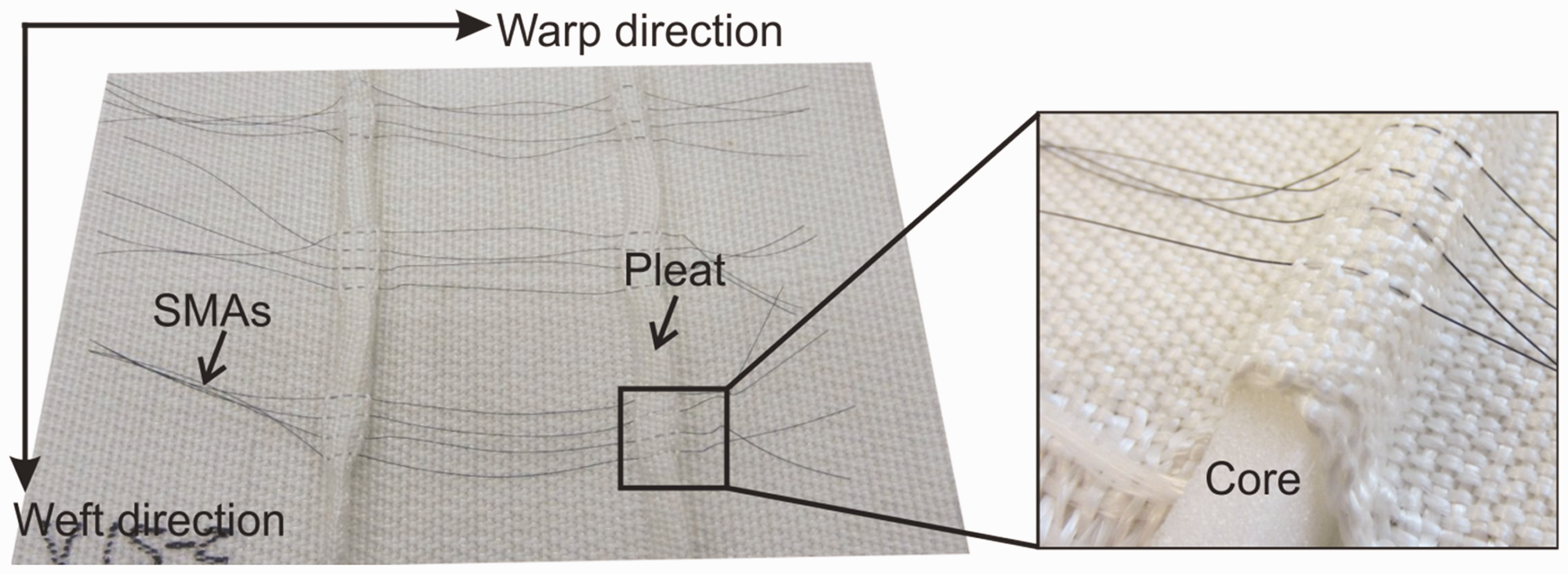
A warp beam each was required to generate the preforms for the upper and lower flaps of the adaptive morphing wing. The warp beam formed the lower fabric layer and the warp yarns were fed via creels to form the upper fabric layer. The warp and weft yarn densities for the fabric layer were seven yarns per cm each. The warp tension applied to the GF-PP hybrid yarn was 4.5 N that was maintained by the interaction between the let off and take up rollers. The preforms developed for the upper flap of the adaptive morphing wing with seven integrated weft yarns in SMAs are presented in Figure 3. The details of the preform development process are described in Ashir et al. [30].
Infusion
A procedure termed vacuum-assisted resin infusion (VARI) was used to infuse the developed preform. The upper and lower flaps of the adaptive morphing wing were infiltrated separately by means of two separate molds with different geometries, as shown in Figure 4.
Lower (left) and upper (right) molds for the infusion of developed preform.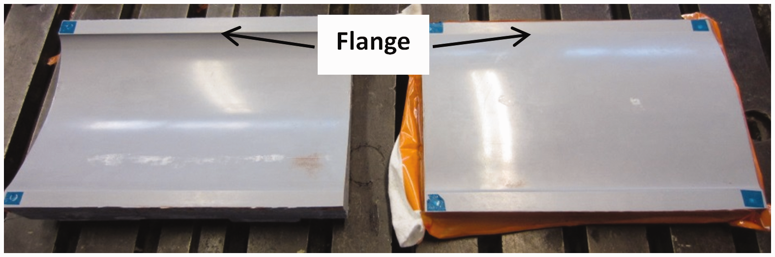
Since the upper preform contains SMAs, they were isolated with tape in preparation for the infusion process. In order to retain the shape of the preform during this procedure, a pseudo core was inserted into the gap between the preform and SMAs (see Figure 5). During the infusion of the upper mold, the sprues were positioned in such a way that the adaptive morphing wing was infused in the longitudinal direction of the pleats. The infusion of the upper mold is presented in Figure 5. The lower mold of the wing was impregnated in the same manner without any special arrangements of tape or foam because the lower layer was free from SMAs and pleats.
Construction for infusion of the upper mold (a) and upper flap of the adaptive morphing wing (b). Black rectangle boxes represent the force transmission area from SMA to adaptive morphing wing. SMA: shape memory alloy.
After infusion, the system was annealed in an oven at 50℃ for 15 h; subsequently, the infused flaps were demolded, and tapes were removed from the SMAs. In a last step, the SMAs were connected by clips to form a continuous electrical path (Figure 5(b)). However, the force is transmitted from SMA to the adaptive morphing wing in the pleat area shown by black rectangle boxes in Figure 5(b), where SMAs are textile-technically integrated into reinforcing fabrics.
The leading edges of the upper and lower flaps of the wing structure were joined in the flange region. The trailing edge was, however, left unjointed so that, during the deformation process, the two halves can move towards each other and SMAs have to overcome some resistance in order to deform. The unjointed trailing edges are illustrated schematically in Figure 6.
Unjointed trailing edge.
Additionally, the preform for the flap was infused as a planar form for the mechanical characterization of FRPs in an adaptive morphing wing.
Testing
Mechanical testing
Norm and dimension of FRPs for characterization.

FRP: fiber-reinforced plastic.
Pull-out testing
Test parameters for pull-out test.

Electrical testing
The adaptive morphing wing was tested in terms of its deformation behavior. A laser triangulator system OptoNCDT ILR 1401-20 (Micro-Epsilon GmbH, Germany) with a measuring range of 20 mm was used to measure the deformation behavior of the wing. Therefore, the component was placed on the table with its top facing down, and the triangulator measured the deformation at the top center of the wing, which is presented in Figure 7. This measuring point was selected because the higher deformation at the top center compared to other positions of the adaptive morphing wing was expected during the testing. By means of a laboratory power supply unit (type: EA-PS 3032-10 B), a thermally induced activation of SMAs in the adaptive morphing wing was performed. The periodic heating (power supply on) as well as subsequent cooling (power supply off) cycles of SMAs were controlled by a LilyPad Arduino unit. The deformation behavior of the adaptive morphing wing was measured by variable current flow and variable periodic time. The testing time was arbitrarily set at 500 s for each variation.
Measuring position for deformation measurements on adaptive morphing wing.
Results and discussion
In this section, the mechanical test results of planar FRPs, the pull-out test results of SMAs from FRPs and the deformation behavior of the adaptive morphing wing with variable current flow in addition to its time-dependent cyclic deformation behavior will be discussed.
Mechanical testing
The typical stress–strain and stress–displacement curves of FRPs in both warp and weft direction resulting from tensile, flexural and impact tests are shown in Figure 8.
Typical stress–strain and stress–displacement curves of FRPs in both warp and weft direction. FRP: fiber-reinforced plastic.
Mechanical test results.

SD: standard deviation.
As revealed in Figure 8, the mechanical properties of FRP in the warp direction are enhanced compared to the weft direction. This phenomenon can be attributed to the undulation of warp and weft yarns. Since glass fibers are brittle, the resulting higher undulation during the weaving process increases the breakage of fibers in GF-PP hybrid yarns. Also, as the reinforcing yarns are composed of GF-PP hybrid yarns with weight fractions of 70% GF and 30% PP, the mechanical properties of FRPs are poorer compared to FRPs exclusively reinforced by glass fibers. A longitudinal and a cross-sectional view of GF-PP hybrid yarn are shown in Figure 9.
Longitudinal (a) and cross-sectional (b) view of GF-PP hybrid yarn. GF-PP: glass fiber polypropylene.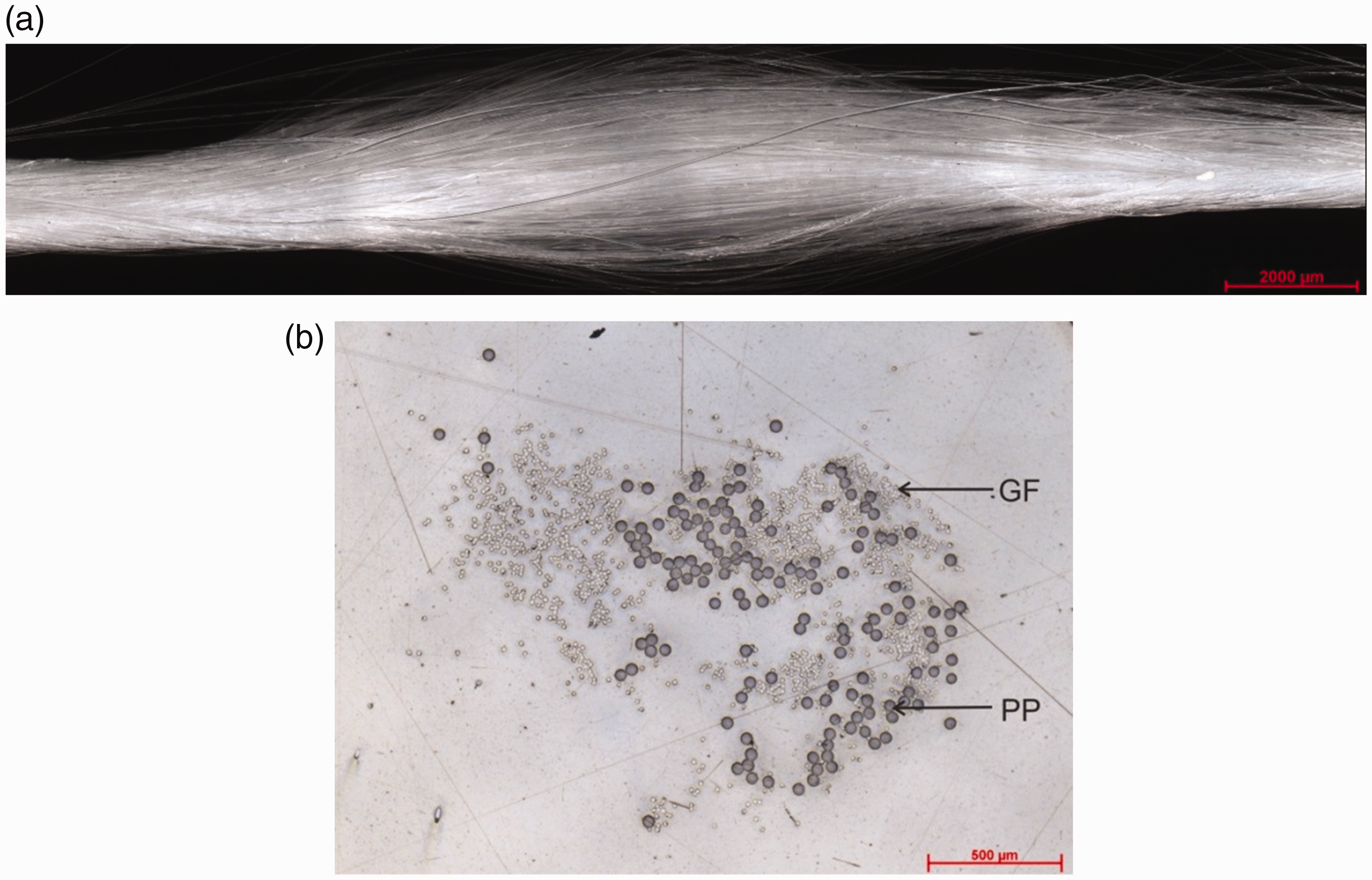
Pull-out test
The force–distance curve and the maximum force required to pull out SMAs from FRPs are illustrated in Figure 10. The graph in Figure 10 reveals that the pull-out force of SMAs from FRPs increases with a rising amount of integrated weft yarns. The contact area for friction between SMAs and FRPs is enlarged by increasing the number of integrated weft yarns in SMAs, which is the reason for this phenomenon. However, it can be concluded that the pull-out force of FRPs with seven integrated weft yarns in SMAs is 4.9 times higher than that of FRPs with three integrated weft yarns in SMAs.
Pull-out force of SMA form FRPs. FRP: fiber-reinforced plastic; SMA: shape memory alloy.
Based on the pull-out force results, the morphing wing with seven integrated weft yarns in SMAs was selected for electrical testing.
Deformation behavior with variable current flow
The deformation behavior of the adaptive morphing wing with variable current flow was evaluated based on maximum deformation and deformation speed. In this test, the current flow was increased gradually from 0.5 A to 1.2 A within a 60s cycle.
Figure 11 suggests that a current flow of 0.5 A was not sufficient to cause deformation of the adaptive morphing wing, whereas deformation did occur at a current flow of 0.6 A. However, this deformation was less than 1.4 mm, and thus no plateau was formed. At 0.8 A, the adaptive morphing wing nearly reached its maximum structural deformation, including the formation of a plateau. The adaptive morphing wing deforms by 2.8 mm (see. Figure 11 – left). Hence, the upper part slided over the lower part, which intensified the deformation effect. No increase in deformation was recorded over a current flow of 1 A. The reason behind this phenomenon is that, below a current flow of 1 A, the adaptive morphing wing cannot exploit its full deformation potential because the phase change temperature of SMA from martensite to austenite lies below this current flow. At a current flow over 1 A, SMA is overheated beyond its transition temperature, and the shape memory effect drops.
Deformation characteristics of the adaptive morphing wing depending on the current flow.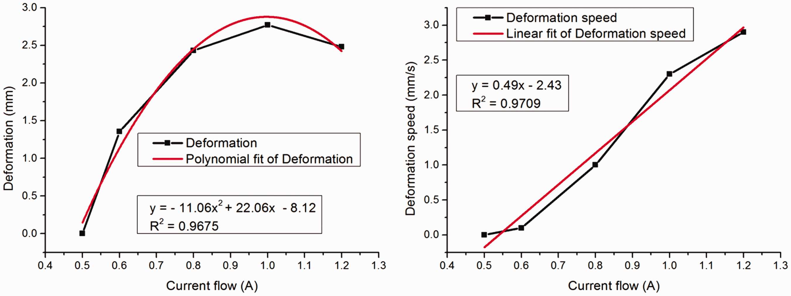
The maximum deformation speed increased steadily with the increase in current intensity, since the SMAs were heated faster. In this research, the deformation speed during the current flow is 2.3 mm/s through 1 A current flow.
Time-dependent cyclic deformation behavior
In addition to the just described deformation, the time-dependent cyclic deformation behavior is also an essential aspect to assess how fast the adaptive morphing wing can deform its maximum during the thermal-induced activation of SMAs [31].
Since the maximum deformation of the adaptive morphing wing occurred at a current flow of 1 A, the time-dependent cyclic deformation behavior of the wing was also tested at a constant current flow of 1 A. The cycle time was set for 20 s, 40 s and 60 s. The time-dependent cyclic deformation behavior of the adaptive morphing wing is demonstrated in Figure 12. Subsequent deformation of the wing structure took place after the thermally induced activation of SMA. Due to the heating and cooling cycles, the plateau width was higher after the 60 s cycle in comparison with the 20 s cycle. However, the plateau was higher during the heating than during the cooling cycle, which applied to all the performed experiments. This is due to the active heating of SMA in adaptive morphing wing by the current flow and the passive cooling by the ambient temperature.
Time-dependent cyclic deformation behavior of the adaptive morphing wing.
The full deformation potential of the investigated adaptive morphing wing was limited by the cyclic thermally induced activation of SMA for 20 s and 40 s. However, the maximum deformation of adaptive morphing wing is slightly higher (1.27%) by the cyclic activation of SMA for 40 s compared to 20 s. In this research, the maximum deformation of the adaptive morphing wing was 2.8 mm, which was achieved by cyclic activating of SMA for 60 s.
Conclusion
The goal of this research project was the development of an adaptive morphing wing based on SMAs and reinforcing fabrics. Two types of preforms were developed based on a varying number of integrated weft yarns in SMAs, and a preferred variant was selected according to the pull-out force. Furthermore, the mechanical characterization of the planar FRP was executed. The deformation behavior of the adaptive morphing wing was tested as a function of current intensity and duration of thermally induced activation through SMAs. The deformation of the adaptive morphing wing was highest at a current flow of 1 A and 60 s of thermally induced activation of SMAs in this particular study.
A potential application scenario of an adaptive morphing wing of this type is the deformation of blade profiles for planes or Formula 1 racing cars, utilized to influence the flow resistance during driving. A time-limited reduction in air flow resistance in Formula 1 is achieved by a drag reduction system (DRS), where the wing can be tilted by a servomotor from 4° to 10°, resulting in reduced resistance (see Figure 13) [32]. Thus, the speed is increased by about 4 km/h.
Principle of DRS. DRS: drag reduction system.
The adaptive morphing wing cannot only replace the tilting of the blade profile, but also lead to a change in the wing shape itself, as outlined in Figure 14.
Principle of wing deformation by contraction in the direction of arrow; orange: effective line inside the profile, black: effective line outside the profile.
Footnotes
Acknowledgements
Financial support is gratefully acknowledged. We like to thank all the participating companies for their technical support and the supply of test material as well as all further partners supporting our research work within this application area.
Declaration of conflicting interests
The author(s) declared no potential conflicts of interest with respect to the research, authorship, and/or publication of this article.
Funding
The author(s) disclosed receipt of the following financial support for the research, authorship, and/or publication of this article: The IGF research projects 18808 BR and 19832 BR of the Forschungsvereinigung “Forschungskuratorium Textil e. V.” are funded through the AiF within the program for supporting the “Industrielle Gemeinschaftsforschung (IGF)“ from funds of the Federal Ministry of Economic Affairs and Energy (BMWi) by a resolution of the German Bundestag.