
Abstract
This paper investigates the tensile properties of 3D orthogonal woven carbon fiber composites with tilted binder by experiment and simulation. The tensile failure strain and fracture mode of this composite show distinguished discrepancy with idealized 3D orthogonal woven composites experimentally. In order to explain this specific failure mechanism, a unit cell finite element model incorporated with damage models of constituents is established to reproduce the damage initiation and propagation of 3D orthogonal woven composites with tilted binder during tensile test. A three-dimensional failure criterion based on Hashin's criterion and Pinho's criterion is utilized to describe the progressive damage of yarns, while the non-linear behavior of the matrix is predicted by Drucker-Prager yield criterion. Besides, a traction-separation law is applied to predict the damage of yarn-matrix interface. The proposed unit cell model is correlated and validated by global stress–strain curves, DIC full-field strain distributions and modulus history curve. The damage evolution process of 3D orthogonal woven carbon fiber composites with tilted binder, including fiber tow failure, matrix cracking, and interfacial debonding, is recorded and investigated by the modulus history curve from simulation.
Keywords
Introduction
Two-dimensional (2D) laminated composites have been widely used in automotive and aerospace industries due to their high specific strength and high specific stiffness. However, laminated composites bear an inevitable risk of delamination in the thickness direction, which hinders their applications in composite structures requiring excellent delamination resistance and impact performance [1–5]. Three-dimensional (3D) woven composites overcome the shortcomings of laminated composites thanks to the additional reinforcement of through-thickness yarns (binder yarns), which interlaces the warp and weft yarns. Besides, the weaving process of 3D woven composites allows for various types of yarns and different woven parameters (such as spacing between yarns, number of layers and so on), which enriches the design flexibility for satisfying specific performance requirements [6]. Furthermore, the net-shape preforms of 3D woven composite structures also could be produced to reduce overall manufacturing cost [7,8].
However, the weave and molding processes of 3D woven composites introduce new defects into the material, such as yarn crimp, yarn distortion, z-binder tilt and so on, which lead to lower in-plane properties compared with 2D laminated composites [9–11]. Specifically, when fabricating complex 3D preforms with variable cross section or forming flat textile reinforcements into a given shape, binders inevitably deviate from the ideal location and deform into irregular shapes due to the change of local woven architecture [12,13]. The deviation and deformation of binders directly result in the distortion of weft yarns and warp yarns, which may have a great impact on the in-plane mechanical properties of 3D woven composites [14].
Various studies were dedicated to investigating the influence of binder on the mechanical behavior of 3D woven composite [15]. Chen et al. [16] reported that the z-binder tows lead to high inter-laminar shear strength for 3D woven composites. Leong et al. [17] carried out an investigation on the in-plane tensile properties of two orthogonally woven composites with different binder paths. It was found that the in-plane fiber yarns in the structure with the longer binder path are less crimped, which had unchanged tensile modulus, strength and strain-to-failure. Saleh et al. [18] had tested three different architectures of 3D woven composites in quasi-static uniaxial tension, and found out that the binder architecture has an effect on directional fiber volume fraction, mechanical properties, failure mechanisms and energy absorption. Castaneda et al. [19] implemented an experimental mechanics approach coupled with multi-physics nondestructive evaluation to investigate the role of binder yarns in the damage behavior of 3D woven composites. The results revealed that binder yarn was associated with transverse reinforcement and coupled with significant out-of-plane effects related to progressively evolving failure patterns. However, to date, the overall effect of tilted binder has not been deeply known or fully investigated.
The quasi-static tensile behavior and damage mechanism of 3D woven composites are quite complex, particularly in the case of carbon fiber composites [20–24]. Under tensile loading along axial directions, the failure occurred by the rupture of load-bearing tows within a relatively localized region [25]. The fracture surface was perpendicular to the loading direction and the crack caused the interfacial debonding between binder and matrix [26]. However, the macroscopic experiment is not capable of capturing and revealing the damage evolution process of the composites. Therefore, finite element methodologies become popular due to their abilities of conducting damage mechanism simulation and providing insights into local responses [27]. A number of progressive damage simulations for 3D woven composites have been reported, among which stiffness-reduction scheme is the most common way to realize damage evolution. Jia et al. [28] reported the damage mechanisms of 3D orthogonal woven composites based on a multi-scale finite element model. The post-damage constitutive models with maximum principal theory failure criteria were adopted to simulate the damage initiation and propagation in resin, while the fiber tows were defined by ultimate strengths failure. Koumpias et al. [29] developed a progressive damage model to simulate the mechanical behavior of 3D fully interlaced woven carbon fiber composite materials. Material property degradation was applied using a damage mechanics-based strain-softening law in the failed elements of the fiber tows. Zhong et al. [30] proposed a continuum damage model for predicting the damage initiation and development for 3D woven carbon fiber composites, which combined the Puck criteria and the paraboloidal yield criterion. The fiber failure, inter–fiber failure, and matrix failure could be considered separately and adequately in this model. Saleh et al. [31] provided a predictive micromechanical model, which simplified the 3DOWC unit cell as a cross-ply laminate. The effect of transverse cracking and shear diffused damage on the in-plane transverse modulus and shear modulus for yarns was investigated. Although binder–matrix interfacial debonding has been observed from the experiment, none of these progressive damage models shows the capability of predicting the yarn-matrix debonding. Besides, the damage evolution of the material is closely related to the modulus (stiffness) degradation, while the modulus history during tensile test has not been used effectively in current literatures.
This work is focused on investigating the tensile properties of 3D orthogonal woven carbon fiber composites with tilted binder, and it is organized as follows. The Experimental procedures section presents the information of material manufacturing and experimental work. The Progressive damage model of 3D woven composites section describes progressive damage model of each constituent. The Development of unit cell finite element model section establishes the unit cell model of 3D woven composites, including geometry, mesh, mechanical parameters of constituents and periodic boundary condition. The Results and discussion section states the experimental observations and the simulation of damage initiation and propagation of 3D woven composites. The Conclusion section lists the concluding remarks from this work.
Experimental procedures
Material preparation
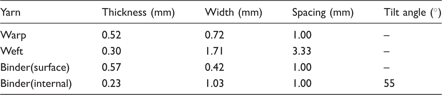
The 3D orthogonal woven composite material studied in this work is manufactured with T700s carbon fiber from Toray. The fabric has a total thickness of 9.5 mm, which consists of eight warp layers and eight weft layers. The warp yarn spacing was kept at 80 ends/cm for the entire fabric, while the weft yarn spacing was set at 24 picks/cm. Figure 1 shows the schematic diagram of idealized 3D orthogonal woven fabrics in TexGen. The epoxy resin, used in this study, is Araldite LY 1572 CI from HUNTSMAN, which has been degassed before infusion. To produce composite plates, the dry fabric was infiltrated with resin using Vacuum Infusion Process under a pressure of one bar. The curing process was carried out at 80℃ for 9 h. During consolidation of the fabric into 3D composites, the thickness of composite panel would decrease. Consequently, binders will be tilted to adapt the change of thickness. After curing, the final size of each composite panel is 350 mm long, 350 mm wide and 7.7 mm thick. The detailed textile architecture parameters of 3D woven carbon fiber composites are shown in Table 1. The overall fiber volume fraction of the composite is 39.4%, which is calculated by measuring the weight of fabric before infusion and the total weight of composite after curing.
Schematic diagram of idealized 3D orthogonal woven fabrics. Detailed textile parameters of 3D orthogonal woven carbon fiber composites.

Internal geometry of material
In order to reconstruct the woven architectures of material, the cross sections of manufactured samples were observed under an optical microscope. The typical cross sections are shown in Figure 2. In Figure 2(a), the dot-dash line shows the binder central path, which is crimped due to compaction during manufacturing. Figure 2(c) illustrates that the binder path is tilted at 55° from the weft direction. The surface binder and internal binder have different geometry since they bear different type of compaction force during manufacturing. The weft yarns show a low degree of waviness and have uniform distribution through thickness in Figure 2(b). The sections of weft yarns are elliptic with similar size. The warp yarns tend to be crimped with the same rhombic sections in Figure 2(a) and (b). The thicknesses of warp yarns have significant differences in Figure 2(a) due to the rhombic section shapes. The average geometric parameters for warp yarn, weft yarn and binder yarn are measured from different microscopic images, as described in Table 2.
Typical cross sections of 3D woven carbon fiber composite panels with tilted binder. (a) Section parallel to warp direction; (b) section parallel to weft direction at position b; (c) section parallel to weft direction at position c. Geometric parameters of studied composites.
Tensile test
Tensile test was carried out on warp and weft direction using CMT5105 with a 100 kN load cell according to ASTM D638 standard (Standard Test Method for Tensile Properties of Plastics). A displacement control of 2 mm/min was applied. At least four specimens were tested for each orientation. The dimensions of the specimens were in accordance with ASTM D638 standard, i.e. 183 mm long with a gauge length of 50 mm. However, the widths of specimens are redesigned to ensure at least five Representative volume unit cells in the width, which are set at 10 mm and 25 mm for warp tension samples and weft tension samples, respectively. Samples required for on-axis testing were cut by Numerically Controlled Production Center. The tensile strain in the gauge was measured by Epsilon L05 laser extensometer, and the full-field strains were also acquired using digital image correlation (DIC) system during tension. White random speckle patterns were applied on a black base coat of the gauge sections of the specimens, providing a pattern for the DIC program to follow. Two digital cameras are used to take pictures through experiments, so that the strain components can be calculated by the DIC software ARAMIS. The optical measurement system of DIC system was set up to take two pictures per second. The experimental setup is illustrated in Figure 3.
Experimental setup.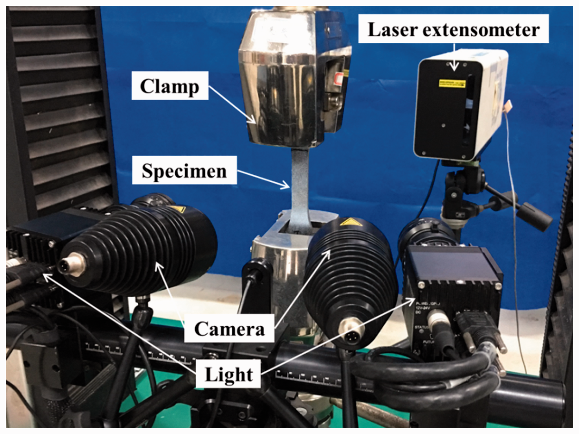
Progressive damage model of 3D woven composites
Progressive damage model of yarns
In the present work, the yarns in the 3D woven carbon fiber composites were treated as unidirectional composites and assumed to have linear elastic behavior before failure initiates. The strains in a unidirectional composite are related to the stresses through Hooke's law for orthotropic materials

The yarns are assumed to be transverse isotropic, then
Pinho's criterion [32,33] and Hashin's [34] criterion, which were developed for laminates, had good performance in the WWFE II [35,36]. Hence, in this study, a three-dimensional failure criterion of yarns based on Hashin's and Pinho's criteria was adopted. The two criteria incorporated with each other to determine the types of failure modes, the damage initiation and propagation of yarns in 3D orthogonal woven composites with tilted binder.
Failure criterion
In this work, three types of failure modes were defined based on Hashin's and Pinho's criteria. These Failure criteria were used to determine failure initiations of yarns. Since fiber compression failure is not the dominate failure mode in tension process, the fiber compression failure criteria has not been included in this work. The criteria for yarn axial tensile failure and yarn transverse failure (including tension and compression failure) are defined as equations (2) and (3), respectively.


The coefficient α is employed to determine the contribution of shear stresses on the yarn axial tensile failure [38], which is considered as 0 in Pinho's work and taken as 1 in Hashin's criteria. Since the special woven architecture of 3D composites in this work may introduce additional shear stresses into the fiber bundles, the value of coefficient α is set to be 1 in this work.
Damage model
When any of failure criteria is satisfied, the formation and propagation of damage initiate in the composite. The damage model adopted in this study is based on Pinho's work [39,40]. The failure propagations of the damage model are different for different failure modes, but all follow a common approach: the components of the traction acting on the potential fracture plane were gradually degraded to zero using a damage evolution factor d as shown in equation (5).

For the axial tension failure criteria, bilinear laws were used to degrade the traction components acting on the potential fracture plane. The damage evolution factor d was defined by equation (6), while the failure strain 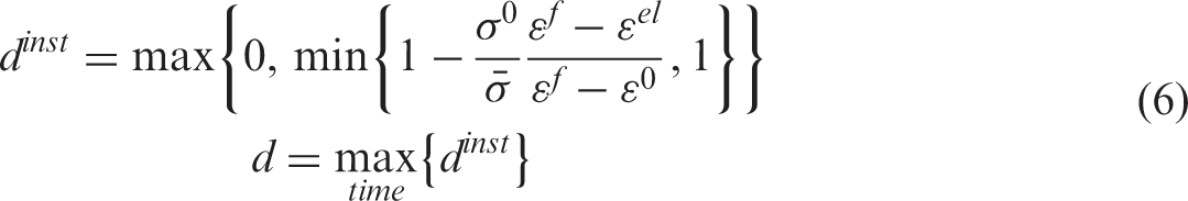

For yarn transverse failure, two different situations can be distinguished by the fracture angle. For a zero degree matrix crack, further cracks follow the formation of the first crack until delamination occurs. In this situation, the damage evolution factor d is defined by equation (8), and the delamination strain 


Damage model of matrix
The epoxy resin matrix has a specific characteristic of hydrostatic stress dependency, which presents different types of stress–strain relationships and failure modes under different forms of loads [41]. In this work, the mechanical behavior of matrix is defined by the Drucker–Prager yield criterion [42] which had taken the effect of hydrostatic stresses into consideration. The Drucker–Prager criterion is expressed as equation (12).

In order to predict the damage mechanism of the current composite, the characteristics of matrix damage and failure should be considered. The shear criterion in ABAQUS was used to simulate the onset of damage of matrix, while the damage evolution was characterized by the progressive degradation of the material stiffness. The stress state of matrix was gradually degraded to zero using a damage evolution factor dm, expressed as equation (13).

Damage model of interface
Interfacial debonding between yarn and matrix had been observed in tensile test of 3D woven composites [26]. Thus, it is necessary to investigate the interfacial properties of 3D woven composites. In this study, the yarn/matrix interface was simulated using cohesive zone modeling (CZM) technology, and cohesive elements (COH3D6) in ABAQUS were adopted in this paper.
The mechanical constitutive behavior of the cohesive elements was defined in terms of a typical bilinear traction–separation law and the elastic behavior was written as

When the deformation of the cohesive element is either purely normal or purely shear to the surface, damage is initiated when the peak values of nominal stress is reached. However, in structural applications of composite materials, interfacial debonding is likely to occur under mixed-mode loading. Figure 4 illustrates a schematic of a bilinear, mixed-mode cohesive zone model. Quadratic nominal stress criterion was adopted in this study to model the initial damage under mixed-mode loading, defined as equation (15)
Illustration of mixed-mode cohesive zone model.


Mechanical properties of interface.

Development of unit cell finite element model
Generation of unit cell model
Since the 3D orthogonal woven composite is generally considered as a periodic array of repeating unit cells, its mechanical performance can be simulated by modelling a unit cell with periodical boundary conditions [46], which begins with the definition of geometry and the generation of mesh. Some specialist pre-processors, which are capable of modelling idealized geometries and providing a convenient voxel meshing tool, are widely adopted to produce an idealized representation of a textile composite [15,27,31]. However, compared with voxel meshing method, the consistent meshing method shows better ability on the description of the woven geometry and simulating damage onset and propagation [47]. The consistent meshing method, which requires periodic mesh and an interface section between yarns and matrix in this work, is still a significant challenge to be accomplished on a unit cell of an inherently complex woven architecture.
The geometric model for 3D orthogonal woven composites with tilted binder was established in NX according to the internal geometric parameters in Table 2. Based on the observation, the weft yarns and binder yarns were assumed to have elliptical cross-section shapes, while the warp yarns have rhombic sections. The warp yarns, weft yarns and binder yarns were modelled as non-crimp yarns in the geometric model. The transition part between internal binders and surface binders were approximately modelled by sweep tool in NX. Figure 5 presents a quarter of geometric model, which has high similarity with the highlight part of the microscopic images in different section views.
A quarter of geometric model compared with the microscopic images: (a) section parallel to warp direction; (b) geometric model parallel to warp direction; (c) section parallel to weft direction; (d) geometric model parallel to weft direction.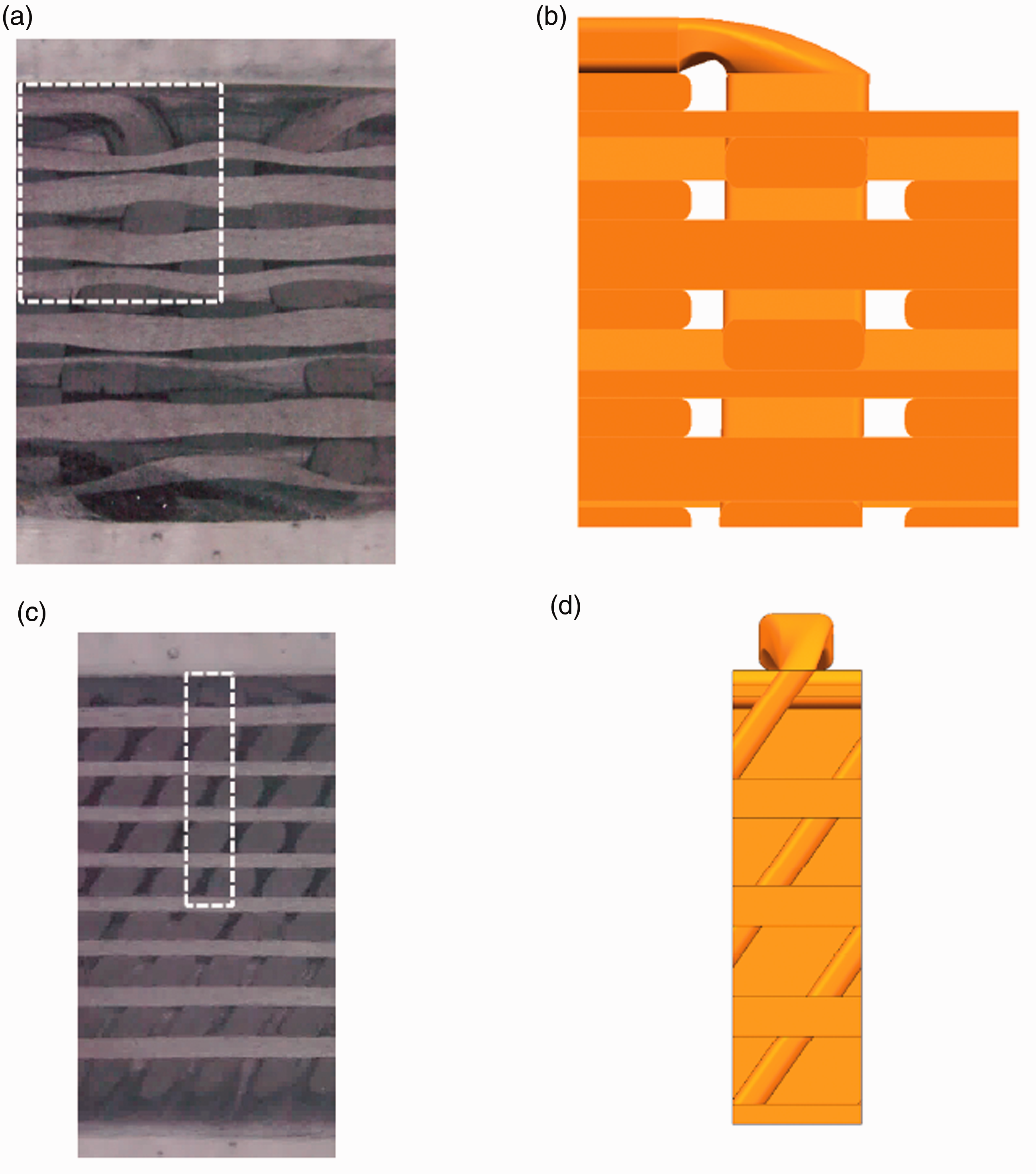
The mesh for unit cell model as shown in Figure 6 was then generated in Hypermesh. A consistent meshing method using tetrahedral elements with four nodes (C3D4) was adopted for meshing the yarns and matrix. The surfaces of yarns were meshed smoothly, and coarse edges were avoided. A convergence study has been performed to find a trade-off between efficiency of simulation and accuracy of local stress. The size of tetrahedral elements is finally set at 0.1 mm. Each yarn was modelled as a transversely isotropic homogeneous composite material, while the resin matrix was modelled as isotropic with the proposed constitutive law. Considering that interfacial debonding had appeared between yarns and matrix, the yarn/matrix interfaces were modelled by cohesive elements in the unit cell model, as illustrated in Figure 6. The unit cell finite element model has 56,671 cohesive elements and 271,998 tetrahedral elements.
The finite element mesh for unit cell model.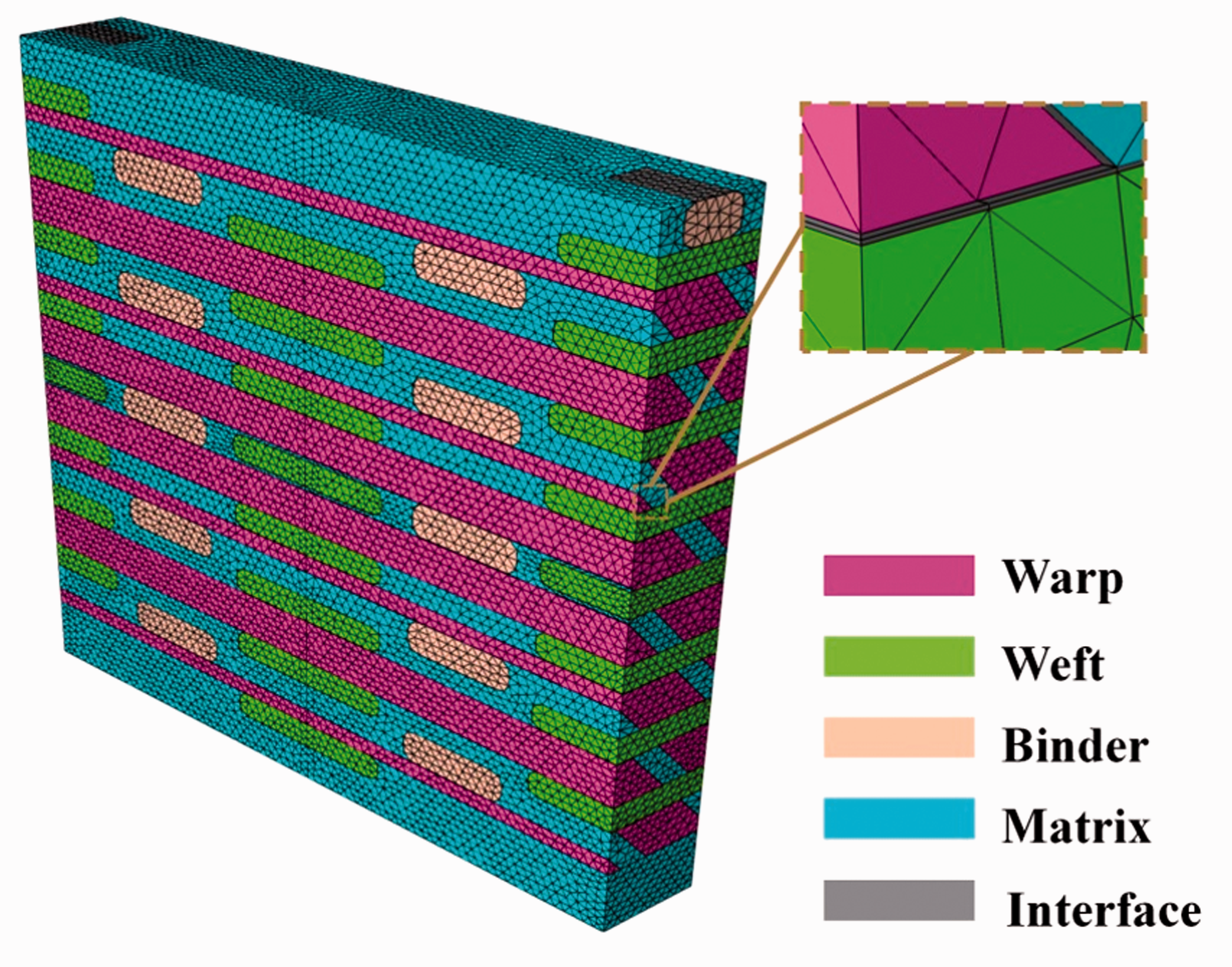
Mechanical properties of yarns
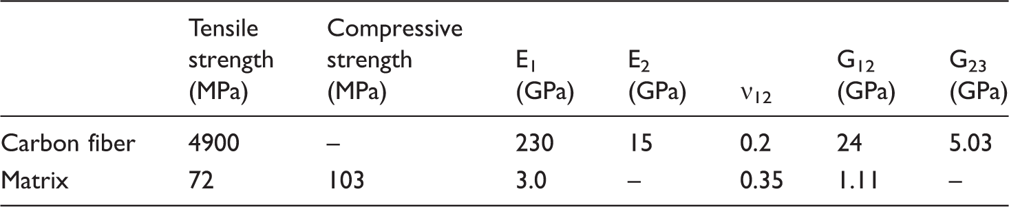
Mechanical properties of carbon fiber and matrix.
Elastic properties of yarns.

The impregnated yarn was considered as a unidirectional composite with a hexagonal packing arrangement, illustrated in Figure 7(a). Three finite element models of hexagonally packed representative volume elements (RVEs) were established for warp yarns, weft yarns and binder yarns, which had different packing factors. The RVE for warp yarn is shown in Figure 7(b) as an example. The RVE was meshed by six-node linear wedge elements of type C3D6. The fiber elements were transversely isotropic, and the resin matrix elements were modelled as elastic isotropic with the proposed constitutive law. It is assumed that fiber mainly undertakes fracture failure and follows the maximum stress criterion under axial loadings. The unified periodic boundary conditions were defined on the RVE to calculate the mechanical behavior of yarns with different packing factors. Detailed information can be found in our previous work [6,48]. The mechanical properties for warp yarns, weft yarns and binders are list in Tables 5 and 6, which are the essential parameters for the establishment of progressive damage model of yarns.
Hexagonally packed RVE: (a) Hexagonal packing arrangement; (b) RVE for warp yarn. Strength properties of yarns.

In order to achieve the periodical characteristics of composites, the periodic boundary conditions should be applied on the unit cell model to represent its repeating nature. The periodic boundary conditions are achieved by coupling the translational degrees of freedom of corresponding nodes on parallel opposite pair of faces. In this work, the equations proposed by Xia et al. [49] were applied via constraint functions in ABAQUS to simulate the tensile loading. A Matlab code was programmed to add node-to-node-based constraints to ABAQUS input file. Periodic boundary conditions were only applied on the opposite pair of faces in warp and weft directions, where the unit cell of 3D woven composites repeated. Then, the reaction forces as a response to the tensile loading can be calculated in ABAQUS. Consequently, the volume averaged stresses and strains of the unit cell were obtained to determine the mechanical properties of 3D orthogonal woven composites with tilted binder under tensile loading.
Results and discussion
Failure mechanism
The experimental results of the tensile properties in warp and weft directions are summarized in Table 7. After the tensile test, post failure analysis was conducted. After warp tension, load bearing yarns (warp yarns) were ruptured whilst the fracture surface was perpendicular to the loading direction. In Figure 8(a), significant warp tow pull-out is observed by fractographic analysis using a scanning electron micro scope (SEM) during warp tension. Figure 8(a) also reveals that binder-matrix debonding happens during warp tension, and leaves a hole on the fracture surface. In Figure 8(b), fiber-matrix adhesion performs well, and fiber wet-out is available in the warp yarn. A significantly distinguish failure pattern was exhibited when loading was applied along the weft direction, shown as Figure 9. The fracture surface is parallel to the tilted binder surface in Figure 9(a), and binder yarn-matrix interfacial debonding is also observed in Figure 9(b). In summary, loading yarn pull-out and binder yarn-matrix interfacial debonding, which were observed in both tensile test, revealed the delamination of interface between yarns and matrix, while fiber-matrix adhesion performed well inside the yarns.
Fractographic analysis for warp tension using a scanning electron micro scope (SEM): (a) fracture surface; (b) warp yarn. The macroscopic failure mode under tensile loading in warp direction: (a) section parallel to the weft direction; (b) view along the thickness direction. Experimental results.


Furthermore, Dhiman et al. [15] and Zhong et al. [30], who used the same type of carbon fiber with this work, found that the tensile failure strains of idealized 3D orthogonal woven composites were larger than 1.65%. However, in this study, the failure of composites occurred suddenly at a strain of 1.25% in weft tension and 1.44% for warp tension, which are significantly lower. In order to verify the relationship between tilted binder and low failure strain, the unit cell with progressive damage models of constituents was used to analyze the mechanical response and failure mechanism of this composite material.
Model correlation results
Figure 10 shows the simulation results of stress–strain curves under axial tension compared with experimental results. The macroscopic stress in the unit cell model was calculated by averaging the reaction forces on the face of the loaded section, while the global strain was computed by dividing the total elongation by the length of the model in the loading direction. As we can see from Figure 10, stress–strain curves from simulation and experiment match well in Young's modulus, but show discrepancy on ultimate strength. The unit cell model predictions and experimental results of the tensile properties are summarized in Table 8. E, σ and ɛ are Young's modulus, failure stress and failure strain, respectively, while subscripts denote the loading directions. The moduli in simulation and experiment were both determined in a strain range of 0.05–0.55% according to the tensile standard. In Table 8, the simulation results of moduli in both loading directions are in good agreement with the experimental results (with error less than 2%). Since the unit cell model neglected the crimp of yarns and the voids in the material, which may lead to an earlier failure, the simulation results overestimated the tensile strength compared to the experimental results (with error less than 13%). The experimental mechanical properties in warp and weft directions showed obvious differences in modulus and strength, since the spacing between weft yarns and warp yarns were inconsistent, as illustrated in Table 2.
Stress–strain curves of experiment and simulation under uniaxial tension: (a) tensile test in warp direction; (b) tensile test in weft direction. Comparison of simulation and experimental results.

A commercial digital-image correlation (DIC) system was used in the study to measure full-field strain and validated the accuracy of the numerical models. The numerically predicted strain distributions of warp tension tests were compared with DIC images, as shown in Figure 11. The presented experimental images, which had the same length of unit cell in warp direction and triple wideness in weft direction, were cut from global DIC pictures. As we can see in Figure 11, the unit cell model captures the surface strain transition from resin-rich zone to surface binder with a reasonable manner.
Comparison of strain contours from DIC and simulation at a global strain level of 1.1%.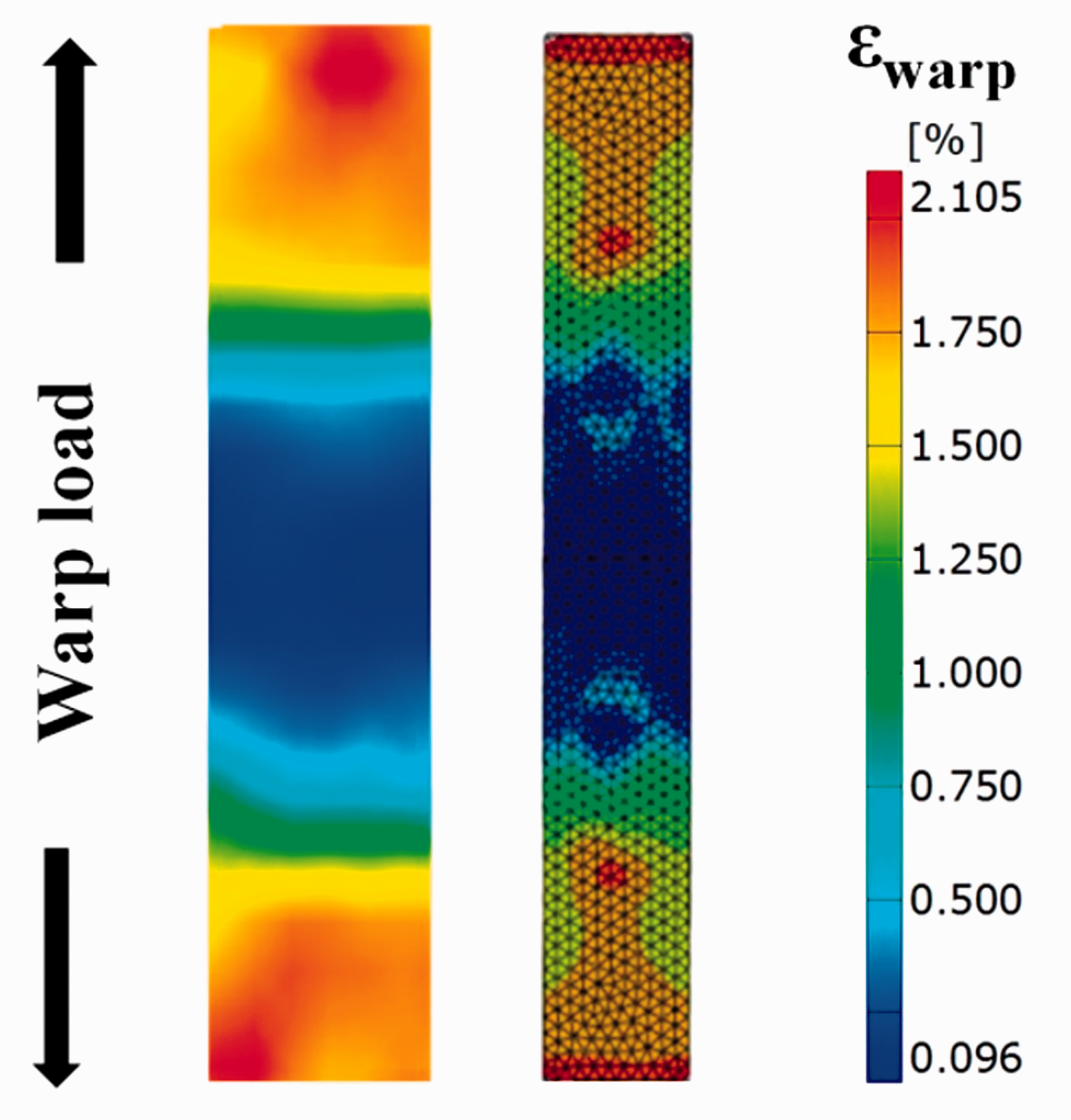
Overall, the detailed correlation in this section reveals that the presented unit cell model gives a reasonably good prediction and can be used to analyze the failure behavior of this composite material.
Progressive damage analysis
The proposed unit cell model has the capacity to capture damage mechanisms such as fiber tow failure, matrix cracking, and interfacial debonding. Contour plots for local damage information can be generated for yarn, matrix and interface at different global strain levels in ABAQUS.
Figure 12 illustrates the modulus history of experiment and simulation under warp tension. The instant modulus in Figure 12 was calculated by a strain gap of 0.005%. In such a small strain gap, the stress increment is not stable for a quasi-static process for experiment and simulation. Therefore, the computed instant modulus of experiment and simulation show obvious oscillation in Figure 12. In order to investigate the trend of modulus history, fitting curves were carried out by polynomial fit with a third-order polynomial. As shown in Figure 12, the fitting curve of experimental instant modulus monotonically decreases with a higher value than simulation predictions in the initial state. The modulus of simulation stays steady without damage formation in the initial state. Then, it shows downtrend in accordance with the experimental results. The marks on the fitting curve of simulation records the onset of different types of failure, which lead to modulus degradation. The interfacial failure between yarn and matrix starts at a global strain of 0.25% in warp yarn and 0.5% in weft yarn, which has a slight influence on the modulus history curve. However, after transverse tension failure initiates, the instant modulus for simulation decreases significantly along with the experimental results. The modulus degradation continues when the matrix failure occurs at a global strain of 1.15%, while the unit cell is suddenly fractured when axial tensile failure initiates.
The modulus history of experiment and simulation under warp tension.
Figure 13 illustrates the contour plot of SDEG at a global strain level of 1.62%, which stands for the scalar stiffness degradation variable of cohesive elements. A value of 0 indicates that stiffness degradation has not occurred yet, while a value of 1 means the element has zero stiffness. As we can see in Figure 13, the yarn/matrix interface of internal binder and warp yarn are close to zero stiffness, which reveals that the interfacial debonding almost occurs around these yarns. Figure 14 shows the contour plots of damage variables at a global strain level of 1.62% under warp tension. The parameters of SDV22 and SDV21 were manually set in Vumat to represent yarn transverse failure and yarn axial tensile failure damage variables, respectively. A value of 0 indicates that there is no damage yet, while a value of 1 means the element is totally damaged and will be deleted in the unit cell model. The yarn transverse failure initiates early but propagates slowly, which is attributed to the stiffness degradation of interface. Consequently, the weft and binder yarn are still not totally damaged until the fracture of the specimen, as illustrated in Figure 14. In Figure 15, the matrix damage propagates from the vicinity of surface binder to the whole resin-rich zone during tension. In the end, the deletions of matrix elements are observed in the resin-rich zone before fracture, which is in accordance with Callus's results [25].
The contour plot of scalar stiffness degradation variable for interface at a global strain of 1.62%. The contour plots of damage variables at global strain of 1.62% under warp tension: (a) yarn transverse failure; (b) yarn axial tensile failure. The contour plots of matrix failure variables: (a) at a global strain of 1.20%; (b) at a global strain of 1.62%.


Figure 16 shows the instant modulus of experiment and simulation under weft tension, where obvious modulus degradation is also identified. The modulus of simulation in the initial state was in good agreement with the experiment results. Then, the modulus declines significantly after the interface failure initiates rather than after the yarn transverse failure. The yarn transverse failure and matrix failure occur almost at the same time with warp tension, but the way of the matrix damage propagation is completely different. The matrix damage under weft tension initiates between the neighboring warp yarns, and propagates along the tilted binder and warp yarn surface, as illustrated in Figure 17. Besides, the yarn-matrix interface around binder and warp yarn is close to zero stiffness, and the weft yarn axial tensile failure also occurs in the vicinity of matrix-weft yarn contact area in Figure 18. Although the failure mode of weft tension cannot be directly obtained by simulation, the most likely fracture surface in the unit cell model is parallel to the tilted binder surface, which is consistent with the experimental results.
The modulus history of experiment and simulation under weft tension. The contour plots of matrix failure variables: (a) at a global strain level of 1.18%; (b) at a global strain level of 1.59%. The contour plots of damage variables at a global strain of 1.59% under weft tension: (a) interface damage; (b) yarn axial tensile failure.


Figure 19 illustrates that the tilted binder structure introduces significant shear stress on the load bearing yarn at a global stain level of 1.5%. The shear stress in the warp yarn distributes on the surface contacted with weft yarns in Figure 19(a), which has a symmetrical and negative-value distribution. The shear stress in the weft yarn shows periodic features correlated with binder yarn positions in Figure 19(b). In Hashin's criterion, shear stress in the yarn has a crucial impact on the damage variable and tensile strength of it. Therefore, the premature tensile failure happens in composites with tilted binder.
Shear stress distribution on the load bearing yarn at a global stain level of 1.5%: (a) warp yarn; (b) weft yarn.
Conclusion
This paper investigates the tensile properties of 3D orthogonal woven carbon fiber composites with tilted binder by experiment and simulation. The fracture surface in weft tension, which is parallel to the tilted binder surface, shows distinguished discrepancy with that of idealized 3D orthogonal woven composites. The tilted binder structure introduces significant shear stress on the load bearing yarn, which may lead to premature tensile failure. The degradation of tensile strength in tilted-binder woven structure should be considered in the design procedure of composite structures.
The progressive damage behavior of 3D orthogonal woven composites with tilted binder is analyzed by using a unit cell finite element model. Before the axial tension failure of load bearing yarns, yarn transverse failure and interfacial debonding had led to significant instant modulus degradation. The matrix damage propagated from the vicinity of binder to the whole resin-rich zone during warp tension, while it initiated between the neighboring warp yarns and propagated along the tilted binder surface under weft tension. The predicted fracture surface in the unit cell model agreed with experimental results in weft tension.
Although the damage evolution process has not been validated by experiment, the proposed general framework of damage analysis incorporated with modulus history is still helpful to record and investigate the damage propagation process. Furthermore, the modeling approach described in this paper can be used for composites with irregular woven architecture.
Declaration of conflicting interests
The author(s) declared no potential conflicts of interest with respect to the research, authorship, and/or publication of this article.
Funding
The author(s) disclosed receipt of the following financial support for the research, authorship, and/or publication of this article: The research leading to the above results was supported by National Natural Science Foundation of China (grant no. 11772191), National Science Foundation for Young Scientists of China (grant no. 51705312) and National Postdoctoral Foundation of China (grant no. 2017M61156).