
Abstract
This paper mainly investigated the cut resistant property of shear thickening fluid enhanced organic high-performance yarn. Cut tests of neat yarn and shear thickening fluids/yarn were performed with two cutting angles. External forces involved in the cutting were analyzed. A simple theoretical relation was established based on the principle of the energy conversion. Two types of shear thickening fluids were prepared. Compared to neat yarn, the shear thickening fluids/yarn exhibited extremely high cut resistant property, especially, shear thickening fluids/yarn with graphene, indicating a synergistic effect. Fracture surfaces of fibers after yarns cut off were initially studied, which verified the cut resistant characteristics of organic high-performance yarns and shear thickening fluids/yarn.
Keywords
Introduction
Flexible protective composites generally made of organic high-performance fibers and shear thickening fluids (STFs) are typically used for a soft body armors to resist the damage caused by bullets and other weapons. A number of researchers have tried to analyze the ballistic and stab resistant property of STF impregnated these fabrics. Additive of STF can largely improve the ballistic and stab resistant performance of the flexible composites [1–3]. However, whether it is a shrapnel or a dagger, which cause cutting injuries to the protective materials. Now, cut resistant mechanism of composite material is undefined, and cut resistance and wearing performance had not reached equilibrium. Cut resistant property of STF-treated yarn is essential to improve the mechanical protective performance of soft body armors.
STFs are non-Newtonian fluids. When shear rate reaches to a critical value, viscosity of STF sharply increases, which translates from a liquid-like state to a solid-like state. In the early days, theoretical investigation on shear thickening mechanism of STF has been conducted by Hoffman and Windhab [4,5]. Kalman et al. [6] have reported that hardness of particles used in synthesis of STF influences its shear thickening behavior and STF with harder particles improve impact energy absorption to a greater extent. Majumdar et al. [7] and Srivastava et al. [8] investigated the role of process parameters and showed that padding pressure significantly influences the impact energy absorption of STF-treated woven Kevlar fabrics. Hasanzadeh and Mottaghitalab [9] provided a detailed review of relevant literature related to rheological properties of STF with particular emphasis on efforts to improve their impact resistance.Specific emphasis is laid on researches that explore ballistic, stab, and puncture protective properties of STF-based materials and body armors. The studies of STF used in bullet and stab resistant materials are very mature, different theories about the mechanism of shear thickening effectiveness have been proposed. However, STF used for cut resistant materials has rarely been reported.
Cutting is simply defined by Persson as “mechanically dividing a solid body along a predetermined line using a cutting tool” [10]. Cut characteristic and mechanism has been proposed by studying the cross-cutting of wood, mechanical slicing of processed foods and orthogonal cutting of metal and carbon fibers reinforced polymer (CFRP) laminates [11–14]. The cut resistant properties of fiber, yarn, and fabric have got more and more attention with regard to their important applications. Kothari and Sreedevi [15] developed a simplified mathematical model to predict cutting behavior of textile fabrics, including a series of 100% cotton woven fabrics with varying pick density and weave pattern (plain, matt, twill, and honeycomb) and another series of fabrics with high-performance fibers, and tried to identify forces involved in cutting. Vu Thi et al. reported that the cut resistance of the material was contributed by the intrinsic strength of material and the frictional distribution. They further discussed two types of friction distributions are involved in cutting: a macroscopic friction induced by the gripping of the material and by the applied normal load on the two sides of the blade; and the other sliding friction associated with cut through of the material that occurs on the face with the blade tip [16]. Cwalina et al. [17] demonstrated that aramid woven textiles intercalated with colloidal STFs, STF Armor™, can provide a meaningful enhancement to the cut and puncture resistance. Moreover, Shin et al. described a test procedure for evaluating the cut resistance of yarns under tension-shear loading conditions. They proposed that the cut energy and strain to initiate cutting depended on the sharpness of the blade, the slicing angle, and the pretension in the yarn, However, there was no systematic and full analysis on factors of cut behavior [18].
In this work, the cut resistant behavior of yarn and STF/yarn were studied by the theoretical and experimental methods. We primarily analyzed external forces involved in the cutting and established a simple mathematical relation. The shear force of STF in the rheological testing was computed, and the correspondence between the shear force of STF at maximum viscosity and the cut resistant force of yarn was initially discussed. Secondly, preparation of STF impregnated yarn and cut experiments were carried out. Experimental data acquired was described to investigate cut resistant properties before and after the STF impregnated yarns. Especially, two recipes of STF with different disperse particles were developed to evaluate the cut proof capability of the flexible composite yarn. Finally, the fracture surfaces of fibers after yarns cut off were studied, which indicated the cut resistant mechanism of these yarns.
Theoretical analysis
To essentially understand the cut characteristic of yarn, several assumptions must be made. Firstly, we supposed that the yarn is a naturally straight monofilament, which can be considered as cylindrical rod. Secondly, we assumed that the yarn is homogeneous, anisotropic, and viscoelastic macromolecule polymer material. The fracture mechanism of the yarn in cutting is conformed to viscoelastic mechanical property of the polymer. Finally, the blade edge is not blunted (staying sharp) during cutting.
External forces involved in cutting
Figure 1 shows the force analysis of the yarn with the both ends fixed in the cutting steady-state, (a) the yarn is cut by the blade with normal load; (b) the yarn is obliquely cut by the blade. In the normal cutting, the applied load acting on the yarn is divided into two parts: cutting force and friction force resulted from grip force between the yarn and the blade. When inclined cutting, the component force of the external force results in yarn slipping along the blade. Therefore, there is sliding friction. Now, what forces and works are required to perform in cutting?
The external force involved of the yarn in the cutting. (a) The yarn is vertically cut by the blade. (b) The yarn is obliquely cut by the blade.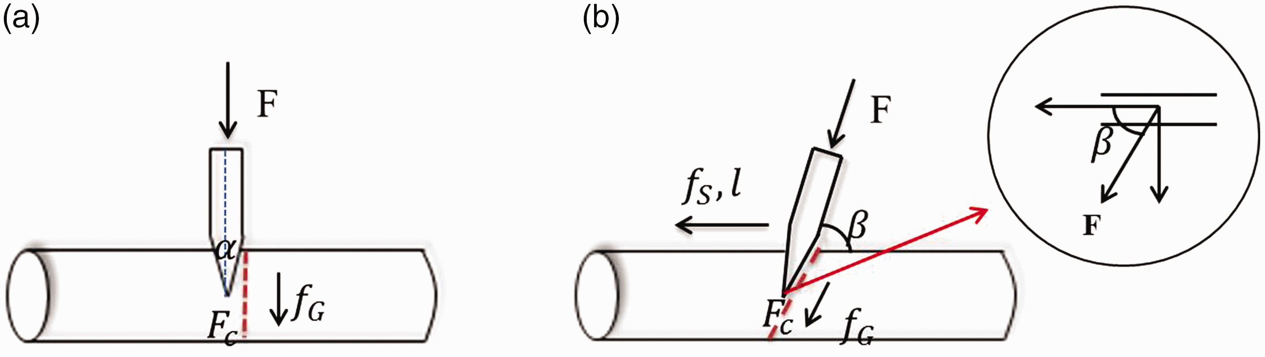
Normal cutting
As shown in Figure 1(a), the external forces consisting of cut force and friction force lead to the internal stress of yarn in the cutting. The slow motion in the cutting re-runs, the internal stress of the yarn is described as three major steps (Figure 2): (a) Initial contact, the internal stress of the yarn is mainly manifested as compressive and tensile stress. At this stage, the yarn is elastic deformation. (b) Crack emergement and penetration in the yarn, which is characterized as in and out-planar shear stress. Anderson [19] proposed three modes of crack propagation: (I) opening, (II) in-plane shear, and (III) out-of-plane shear. Depending on the cutting conditions, it is likely that yarn fails with a mixture of these three modes. (c) Complete separation, the fracture surface of the yarn is deformed, and its section area becomes larger, which relate to the viscous flow between molecules of viscoelastic polymer material. There is a hypothesis that the compression and axial tension resulting from the initial contact between the yarn and the blade are negligible, so long as the blade edge is very sharp, and the cut runs ahead of the tip of the blade. The efficiency of each step mainly depended on the sharpness and fineness of the blade edge. The sharpness of the blade is represented by the radius ratio between the blade and the yarn, which is not the study scope of this paper [20].
The schematic graph of the cut process of the yarn. (a) Initial contact. (b) Crack emergement and penetration. (c) Complete separation.
According to the principle of energy conservation [21], the works done by the external forces acting on the yarn are equal with the internal energy of the yarn in the steady-state cutting system.


Inclined cutting
The cut fracture behavior of the yarn in the inclined cutting is similar to that of yarn in the normal cutting. There is added sliding friction force between blade and yarn. Furthermore, when the yarn is obliquely cut by the blade, contact area between blade and yarn becomes larger, seen red dotted line in Figure 1(b). So, equation of energy conservation is as follows


Shear thickening mechanism of STF
There are two main theories proposed by researchers on shear-thickening mechanism of STF: Order-disorder theory and hydrodynamic clustering theory. Now, hydrodynamic clustering theory is much more recognized and studied, which results from strong hydrodynamic force generated by the Brownian motion among clusters of particles [23,24]. In the stable rheological test of STF, with shear rate increased, microstructure of colloidal suspensions undergoes three stages: (1) equilibrium, which means the balance between hydrodynamic and Brownian forces. In this stage, STF is a stable colloidal suspension. (2) Perikinetic aggregation, which is due to Brownian motion and is relevant to nanoparticles. This stage shows shear thinning. (3) Orthokinetic aggregation, in which hydrodynamic interactions become predominant. It shows shear thickening, as shown in Figure 3.
The shear thickening mechanism of shear thickening fluid.
For a particular shear thinning or thickening fluid, there is a certain relationship between the shear rate and the shear stress, which consistent with the following equation


The mechanical property of STF including the critical shear force and the maximum shear force in the rheological testing will be investigated to analyze shear thickening effect of STF in the in-plane shear mode. It is significant for the practical application of STF.
Experiments
Preparation of STF and STF/yarn
STFs were prepared with disperse medium and disperse phase. Disperse medium made from polyethylene glycol with unit molecule weight 200 and 400 g/mol (PEG 200 and PEG 400) (Sinopharm Chemical Reagent Co., Ltd.), which were compounded in the volume fraction of 1:2. Two shapes disperse particles, including spherical silica nanoparticles, which have 690 nm in diameter (Evonik Degussa Co. Ltd.), flaky graphene nanoparticles with 1–5 nm in thickness and 5–20 µm in diameter (Shenzhen nano Port Co., Ltd.) were provided. With same disperse medium, two formulas STFs were prepared. The disperse particle of the one type of STF (STF1) contain only spherical silica nanoparticles, and its solid content is 75% whereas the disperse particles of the other one (STF2) are made of flaky graphene nanoparticles and spherical silica nanoparticles; their solid content, respectively, is 5% and 70%. To obtain stable and uniform STF, the STF was placed in the mechanical stirrer up to 24 h. Furthermore, The STF was treated in vacuum for 24 h to exclude the bubbles.
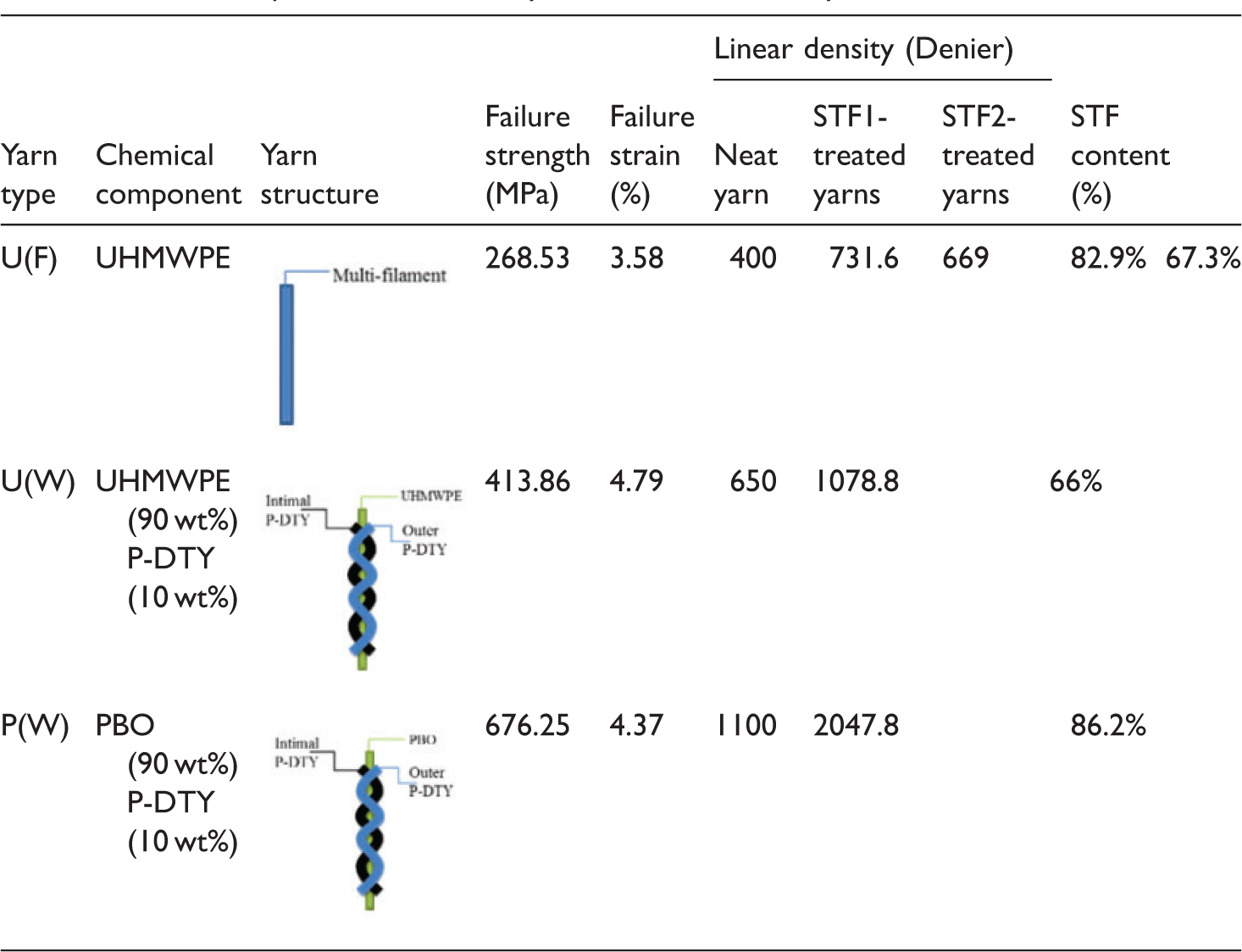
A series of organic high-performance yarns (Beijing Junantai Protection Technologies Co., Ltd) made of 100% multifilaments with slight twist (50 twists/10 cm) of Ultra High Molecular Weight Polyethylene fibers (UHMWPE, 736 filaments per yarn and The microscopic image of yarns before and after impregnated by STF. (a) Neat yarn. (b) STF1-treated yarn. (c) STF2-treated yarn. The basic parameters of neat yarns and STF-treated yarns.
Test equipment
The stable rheological test of the STF was done using Anton Parr company MCR 301 stress-controlled rheometer using parallel plate geometry. The gap between the two parallel plates was kept at 0.5 mm. The shear rate was increased from 0 to 200 s−1, and corresponding viscosity was measured at ordinary temperature (25℃).
The cut tests of yarns were done on the transformed Instron with 250 N upper limit of load cell capacity. A custom-designed accessory which is U-shape displaced the bottom clamp of Instron. There are several holes on both sides of the U-shaped fixture, the cutter is mounted on this fixture with screw bolts. Then, cut angle can be adjusted through these holes (Figure 5(a)). The blade is rounded by the yarn. The two ends of the specimen are simultaneously gripped by up clamp. The yarn is pretensioned to 10% of the yarn's tensile strength (Figure 5(b)). The blade used for cut test is rectangular and made of stainless steel of hardness greater than 45 HRC. The thickness of the blade is 1.0 ± 0.5 mm, the blade has a cutting edge length greater than 150 mm, and its width is more than 45 mm (Figure 5(c)).
The cut equipment of the yarn. (a) Schematic diagram of cut set-up. (b) Schematic diagram of yarn position. (c) The blade.
Cut test method
Cut tests were divided into two systems consisting of neat yarns and STF impregnated yarns. The yarn was held by an upper clamp raised at some velocity until they were contacted, loaded, and then completely severed, raw displacement-load curves were measured. Cut angles were considered as orthogonal cutting (90°) and inclined cutting (68°). Each experiment had five repetitions. In addition to the cutting fracture, tensile fracture exists in the cutting, and tensile fracture of yarn as a common factor will be considered in the latter analysis. SEM was supplemented to analyze the fracture surface characteristic of neat yarns and STF/yarns.
Results and discussion
Neat yarns
Figure 6 shows cut resistant properties of neat yarns in the orthogonal and inclined cutting directions. Because the linear density of each yarn is different, the cut resistance of the yarns cannot be visually indicated. The peak cut force is normalized by the linear density of the yarn, which is named as the specific anti-cutting force. In the orthogonal cutting, yarn fracture occurred predominantly at the same location of the blade tip. In the inclined cutting, however, the yarn slipped upwards along the blade in the cutting process. For the same material, The intrinsic fracture toughness of the material ( The cut resistant property of all neat yarns. (a) The normal cut direction. (b) The inclined cut direction. (c) The peak load of all neat yarn.
STF/yarns
The rheological properties of the two types of STFs are shown in Figure 7, (a) the shear rate–viscosity curve, (b) the shear stress–viscosity curve. They exhibited the shear thickening behavior with increasing shear rate or shear stress. Previous studies had proposed that the viscosity of STFs obviously increased when shear rate reached some critical value. The STF changed from colloid to quasi-solid. The rheological test of the STF2 with spherical silica and plate graphene nanoparticles appeared lower critical shear rate. Furthermore, the shear-thickening phenomenon happened sharply. There is scarcely shear-thinning phenomenon in the initial shear rate stage. The viscosity of STF2 exceeded to that of STF1 with an increase in the shear rate. The interaction between disperse particles increased as disperse particles concentration increased. Moreover, the graphene is a plate structure and has a larger specific surface energy that facilitates particle agglomeration and more easily filled with voids between globular silica particles during thickening stage.
The rheological property of the shear thickening fluid (STF). (a) The relationship between viscosity of STFs and shearing rate. (b) The relationship between viscosity of STFs and shearing force.
Figure 8 shows the cut resistant property of two formulas STF-treated yarns. The peak cut force of the basic formula STF (only silica) impregnated yarn is greater than neat yarns, regardless of the yarn material. Whether it is normal cutting or oblique cutting. It is obvious that the STF addition enhanced the cut resistant performance of the yarn. Moreover, addition of flaky graphene nanoparticles to STF can further improve cut resistant property of yarn. Schematic diagram of cut resistant mechanism of neat yarn and STF/yarn is shown in Figure 9. Firstly, the fracture toughness of the yarn is critical to enhance cut resistance of the yarn. Disperse particles consisting of silica and graphene have strong hardness and can improve the fracture toughness of the STF/yarn. Secondly, the external force acting on the yarn was divided into two parts: the friction force and the cutting force. The surface of the STF/yarns is rougher than the neat yarn. STF/yarns hardly slip in the inclined cutting. The surface friction coefficient of the STF/yarn was improved. Sliding friction work is few. Work done by the cutting force almost all contribute to fracture energy of yarn, so, the larger cutting force is required. Thirdly, comparing the cut force of the STF/yarn in the cutting to the shear force of the STF at the maximum viscosity, STF in the yarns played a shear thickening effect during the cutting process.
The cutting resistance property of the STF-treated yarns. (a) STF1-treated yarns with normal cutting. (b) STF1- and STF2-treated U(F) yarn with orthogonal and inclined cutting. The schematic diagram of cut resistant mechanism of the specimen. (a) Neat yarn. (b) STF/yarn.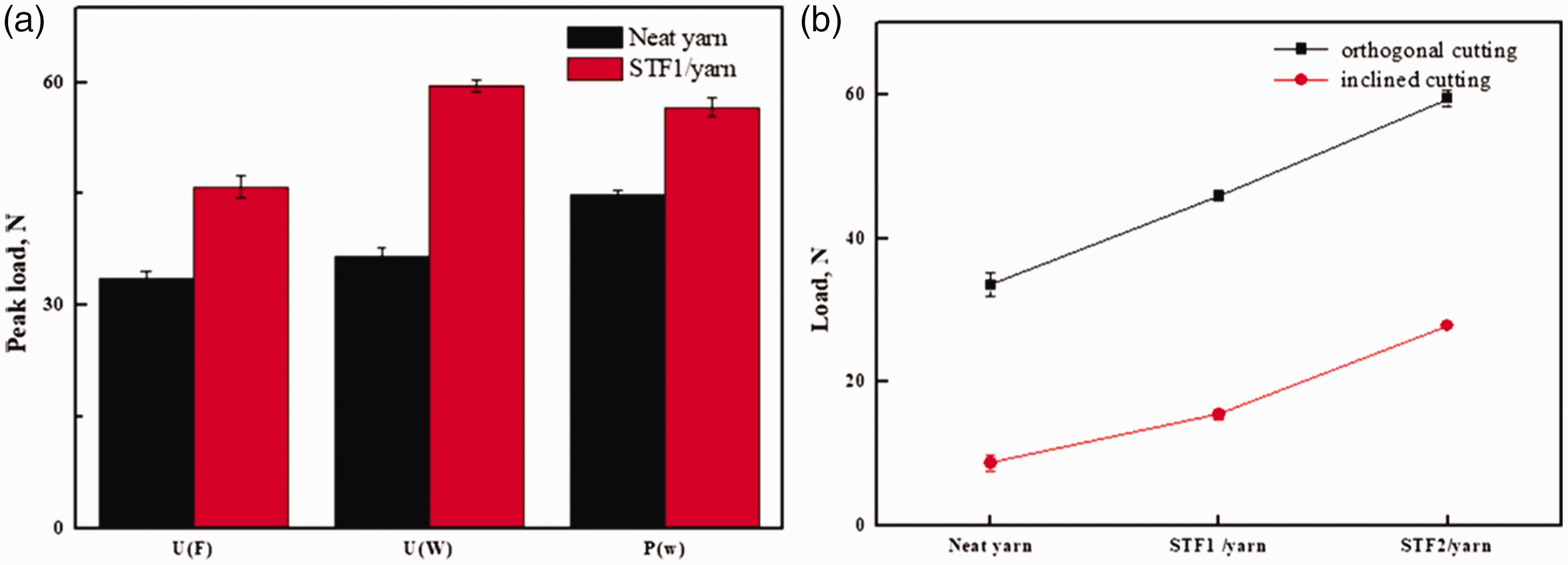

Fracture surface
To analyze the cut failure modes of yarn, the morphologies of fracture surfaces of yarns are important information. Figure 10 shows the SEM micrograph of the cutting fracture of the neat yarns. Whether it is normal cutting or oblique cutting, clearly, the yarn was subject to cutting fracture. From Figure 10(a), the cut fracture surface of the yarn is flat and smooth, the broken ends of the yarn is mushroom shape due to the viscoelasticity of the material. Many researchers considered that the deformation of the organic high-performance fiber as a viscoelastic material has time dependence, which depends largely on intrinsic molecular composition of fibrous materials [26,27]. According to Figure 10(b), there is a slanting cut cross-section of the yarn in the inclined cutting. It signified that the cut fracture mode of the yarn was affected by the cut angles. Furthermore, the cut tests of the yarn were added with a duller blade edge. The yarns were damaged by the blade with cut and tensile modes. When the yarn with both ends clamped was contact with the duller blade in the low velocity, with the tensile deformation, the yarn was gradually cut by the blade. So, the front section of the yarn was subjected to cut failure with neat fracture surface, yet, the back section of the yarn was stretched failure.
SEM micrograph of fracture surface of neat yarn. (a) Normal cutting. (b) Inclined cutting.
Figure 11 shows SEM micrograph of the cut fracture surfaces of STF-treated yarns. From Figure 11(a) and (b), the lateral shapes of the cut fracture surface of the STF1- and STF2-treated yarns were similar to neat yarn. The fracture surface of the STFs/yarns was coated by STF. It demonstrated the effect of shear thickening was achieved by the movement of nanoparticles in the cutting, indicating a synergistic effect. Due to the existence of inorganic silica and graphene nanoparticles, cut fracture surface areas of the STF-treated yarns became smaller, which should be based on brittle fracture mechanics. Mayo et al. [28] verified all organic fibers demonstrated similar modes of cut resistance, and isotropic, inorganic glass fibers failed according to simple, localized brittle fracture. The cut fracture mechanism of the viscoelastic fiber material will be the focus of later research.
SEM micrograph of fracture surface of STF-treated yarns. (a) STF2-treated yarn. (b) STF1-treated yarn.
Conclusions
The paper firstly analyzed external forces involved in the cutting and established a simple theoretical relation based on the principle of the energy conversion. For the normal cutting, external forces involved of yarn contain cut force and friction due to grip force. For the inclined cutting, there is sliding friction except from above two types of forces. Experiments were conducted to estimate friction effect in the inclined cutting. Cut angles have great influence on the cutting behavior of yarns. It is reasonable using this model to explain cut characteristic of yarn.
The correspondence between shear force at the maximum viscosity in the rheological testing and cut force of the material is proposed for the first time. Experimental investigations verify that shear thickening effect of STF can improve cut resistance of yarn. Moreover, analysis of experimental data indicated that addition of flaky graphene nanoparticles to STF more effectively improve the cutting resistance of the yarn. There are three reasons to explain higher cut resistant property of STF/yarn. Firstly, STF had reached the maximum viscosity in the cut force region of STF/yarn, which manifest that shear thickening behavior of STF contributes to the anti-cutting performance of STF/yarn. Secondly, SEM shows that STF adheres to surface of yarn. Silica and graphene in the STF/yarn can improve hardness of yarn, thus, improve fracture toughness of yarn. Thirdly, the surface of the STF/yarns is rougher than the neat yarn. So, yarns hardly slip in the inclined cutting. Sliding friction work is few. Work done by the cutting force almost all contribute to fracture energy of yarn, so, the larger cutting force is required.
Fracture surfaces of fibers after yarns cut off were first studied. The cutting end of organic high-performance fibers is mushroom shape. With different fiber material, lateral area of the cutting end of the yarn is diversified, which depend largely on intrinsic molecular composition of fibrous materials. These will be the focus of our future studies. SEM micrograph showed that the fracture surface of STF-treated yarns is covered by silica and graphene nanoparticles. It indicated that disperse particles of STF were flowing and active in the cutting, which resulted from shear thickening behavior, indicating a synergistic effect. So, the STF-treated yarn had better cut resistance.
Footnotes
Declaration of conflicting interests
The author(s) declared no potential conflicts of interest with respect to the research, authorship, and/or publication of this article.
Funding
The author(s) disclosed receipt of the following financial support for the research, authorship, and/or publication of this article: This work was supported by Jiangsu Advanced Textile Engineering Technology Center Project (no. XJFZ/2016/13) and Jiangsu Graduate Research and Innovation Project (KYCX17_1449). The city industry key technology foresight and common science and technology projects of Lianyungang (CG1520).