
Abstract
Textiles can have valuable functions in terms of measurement, detection and communication when they are incorporated into functional electronic devices. However, the additional electric circuits limit the flexibility and extensibility, making the wearers uncomfortable and the manufacturing difficult. Therefore, in this study, conductive elastic knits are made of metallic yarns and expected to be used as wearable electronic textiles. In order to retain the flexibility of knits, a crochet machine with jacquard equipment is used to create knit patterns as electric circuits. Regardless of whether it is single-twisted yarn, double-twisted yarn, single-wrapped yarn, or double-wrapped yarn, the metallic wires can be completely covered in polyester filaments. Variations in twist numbers of conductive yarns or knit patterns are beneficial to the tensile strength with a maximum increment of 14%, and changing twist numbers of conductive yarns or knit patterns have a positive influence on the air permeability with a maximum increment of 24%. According to the results of the electric circuit stability test, using double-covered yarns ensures the knits a stabilized electric circuit regardless of the knit pattern.
Introduction
Wearable electronic textiles are a new field that synthesizes electric and textile techniques. They have comfort and flexibility and can be applied in the recreation, sports, and medical fields [1]. On the other hand, garments that are composed of wearable electronic textiles require comfortable texture and ease of production, which makes the tensile properties, elastic recovery, efficient cutting of the wearable electronic textiles crucial to the production and wearers’ preference [2]. There are a great number of studies on the textiles in relation to the mechanical properties of fabric structure and yarn composition [3–5]. This indicates that conductive knits composed of metallic wires [6] or unwrapped conductive yarns [1,4,7,8] have an electrical resistance that is affected by an externally imposed force. The majority of studies on conductive yarns emphasize on the electrical conductivity [7,9], and there are few studies focusing on the protective layer of conductive yarns, where only a few researchers attempt to reach this goal using embroidery [8].
Twisting and wrapping are commonly used to combine metallic wires and polymer filaments for the production of conductive yarns with good electrical conductivity and mechanical properties [10]. However, the resulting wrapped yarns or twisted yarns have low extensibility due to their structural features, and are thus rarely made into wearable electronic textiles. Flexibility and extensibility are two novel features of electric circuits, and currently, some techniques are used to provide electric circuits with extensibility by means of using local deformation. For example, mold casting is used to make electric circuits with a horseshoe pattern, shaping a curved radius in order to improve the extensibility [11–14]. However, electric circuits formed by mold casting exhibit stress concentration on the edge, which makes extra protection to maintain the stability of electric circuits essential.
Knits are a suitable material for wearable electronic textiles as they have high softness, air permeability and extensibility, and can significantly improve the comfort of wearers. A crochet machine is a warp knitting machine with special specifications, providing knits with different functions using the combinations of yarn and knit structure [15,16]. The warp knitted fabrics that are composed of rubber threads have excellent elasticity [17–20]. They can be combined with metallic yarns to form electromagnetic shielding knits, but using a great amount of metallic yarns results in an increase in rigidity of the knits.
The electric conductivity and electrical stability of current conductive polymer yarns are not as good those of metallic yarns, which makes metallic yarns a very suitable candidate to be used in the field of wearable textiles. However, metallic yarns have a low extensibility and cannot be fabricated into knits easily. Most scholars chose to use other types of conductive yarn, such as conductive polymer yarns. There are no previous studies changing the knit structure of metallic yarns to improve the low feasibility of fabrication.
In this study, a crochet machine with jacquard equipment is used to make metallic wires into a horseshoe pattern. The expanded structure is expected to improve the difficulty of fabricating metallic yarns. In addition, many studies investigated the mechanical properties of twisted or wrapped metallic yarns, but few studies investigated the electrical stability of both twisted and wrapped yarns that are made in different forms simulating the real wearing status. Therefore, this study proposes conductive elastic knits that can be used as wearable electronic textiles. The composition, mechanical properties, air permeability, tensile properties, and electric circuit stability are evaluated, thereby examining whether the conductive yarns have completely covered metallic wires and conductive knit patterns can be easily formed. A crochet machine is used to fabricate the conductive twisted or wrapped yarns into conductive elastic knits, and its jacquard equipment creates knit pattern to serve as electric circuits. The proposed wearable electronic textiles thus preserve the softness of knits while obtaining extensibility of electric circuits. In this study, the conductive elastic knits are combined with a sensor for the application of wearable textiles that are designated to wear in arms and forearms. They are tested with the short circuit test, washing test, abrasion test, and electrical resistance test are conducted in order to examine the stability of electric circuits. Moreover, the flat and curved surfaces of the samples are both used to simulate the knits when being really worn and to evaluate the short circuit and electrical resistivity. The washing test and abrasion test are performed to predict the damage by laundry and replicate the abrasion loss for authentic use.
Experimental
Materials
Conductive polymer yarns are made of coating conductive polymer over the yarns or adding conductive powders to the yarns. However, these two methods do not produce conductive yarns with good electrical stability. When a tensile force is externally applied to the conductive polymer yarns, the coated conductive polymer peel off and create cracks, and are thus unable to create a conductive network. Moreover, adding conductive powders to polymer is subjected to agglomeration. The unevenly distributed conductive powders may cause a high electrical resistance. By contrast, the metallic yarns have greater electric conductivity and electrical stability.
Specifications of materials.

Preparation of conductive yarns
Parameter of conductive yarns.

Note: The four conductive yarns are defined as follows. Twisted yarns are at least two plies of yarns that are twisted using a rotor machine. In this study, different s of PET filaments are twisted with a metallic wire, and the twisted yarns are named as S-twisted yarns and D-twisted yarns where “S” means single PET filament and “D” means double PET filaments. Moreover, wrapped yarns are at least two plies of yarns that are made into the core and the sheath, and are named as S-wrapped yarns and D-wrapped yarns where “S” means single PET filament and “D” means double PET filaments.
Figure 1 shows the schematic diagrams of the rotor spindle machine assembly and the structure of a twisted yarn. The PET filament and metallic wire are twisted and then intertwined using a rotor spindle machine, and the twisted yarns eventually appear in a spiral structure (Figure 1(b)).
(a) The assembly of a rotor spindle machine and (b) shows the structure of twisted yarns.
Figure 2 shows the assembly of a hollow spindle machine and the structure of a wrapped yarn. PET filaments are used as the sheath and metallic wires are used as the core. The sheath-core structure is thus compact as seen in Figure 2(b).
(a) Assembly of hollow spindle machine and (b) diagram of a wrapped yarn.
The twist number is computed using the differences in the rotary speed of the package device and take-up roller. The equation is as follows

Preparation of conductive elastic knits
Conductive elastic knits are composed of conductive yarn and elastic knits. PET filaments are used as the warp yarn and the weft inlay yarn, while rubber threads are used as the warp inlay yarn. The warp yarn and warp inlay yarn comprise the chain stitch, which is then cascaded with the weft inlay yarn to form the elastic knits. During this process, the conductive yarn is simultaneously knitted on the back side of the knits, thereby forming the conductive elastic knits. The structure of the conductive elastic knits is shown in Figure 3. There are a total of 48 conductive elastic knits, which are combinations of four conductive yarn types (S-twisted, D-twisted, S-wrapped, and D-wrapped yarns) at three twist numbers (5, 10, and 15 for the twisted yarns, and 20, 25, and 30 for the wrapped yarns, respectively), and four knit patterns (A, B, C, and D). The specifications of the knits are shown in Table 3. The knit patterns are formed using the jacquard equipment, allowing the conductive yarns can be displaced between different warp yarns as shown in Figure 4 where the warp yarns are marked in black and the different paths are marked in orange. According to the different paths of the conductive yarns in the warp yarns, the knit patterns are divided into patterns A and D.
Schematic diagram of the structure of conductive elastic knits, where the black yarn is the warp yarn, the red yarn is the rubber thread, the blue yarn is the weft inlay yarn, and the orange yarn is the conductive yarn. Specifications of conductive elastic knits. CEK: conductive elastic knits; DT: D-twisted yarns; DW: D-wrapped yarns; ST: S-twisted yarns; SW: S-wrapped yarns. Note: ST, DT, SW, and DW indicate the specifications of conductive yarns. Schematic illustration of conductive elastic knits where the warp yarns are marked in black and the paths that the conductive yarns intertwine the warp yarns are marked in orange.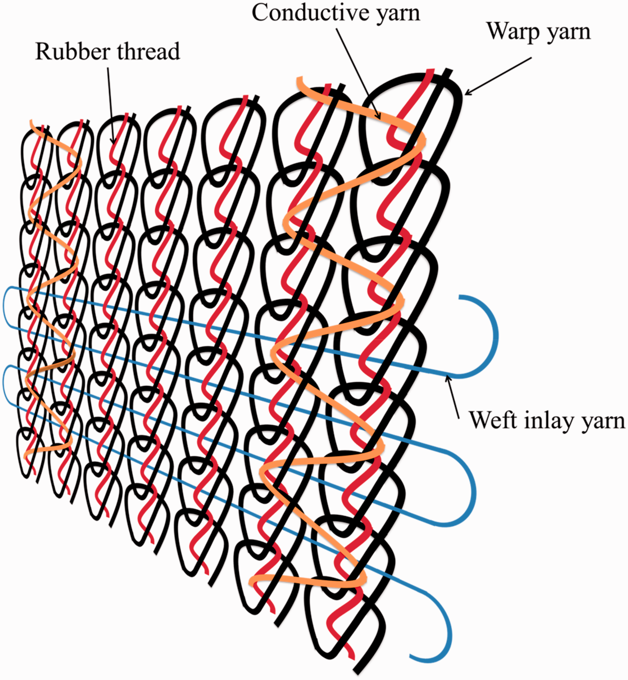


Properties tests
Tensile properties of conductive yarns
As specified in ASTM D2256, an automatic yarn tester (FPA/M, Statimat-M, Textechno Ltd, Western-Germany) is used to measure the tenacity and elongation at break of the conductive yarns. The distance between gauges is 250 mm and the tensile rate is 300 mm/min. Twenty samples for each specification are used in order to have the mean.
Air permeability
This test follows ASTM D737. The conductive elastic knits are tested for the air permeability using an air permeability tester (Textest FX3300, Switzerland). Samples have a size of 25 × 25 cm. Twelve samples for each specification are used in order to have the mean.
Tensile properties of conductive elastic knits
This test follows ASTM D5034. The conductive elastic knits are tested for the tensile stress and elongation at break at a tensile rate of 300 mm/min using a universal testing machine (HT-2402, Hung Ta Instrument Co. Ltd, Taiwan). The distance between the upper and lower gauges is 100 mm. Samples have a size of 20 × 2.5 cm, and 10 samples for each specification are used in order to have the mean.
Elastic recovery rate
Elastic recovery rate is defined as the recovery of length (%) of the sample after the elastic deformation. This test follows FZ/T 70006-2004. The conductive elastic knits are tested for the elastic recovery rate at a tensile rate of 300 mm/min using a universal testing machine (HT-2402, Hung Ta Instrument Co. Ltd, Taiwan). The distance between gauges is 100 mm. Samples have a size of 20 × 2.5 cm and five samples for each specification are used in order to have the mean. Samples are expanded to the 70% of the maximum elongation rate for 60 s and released to the original length and retain for 60 s. This cycle is repeated five times on each sample.

Electric circuit stability
A custom-made Light-emitting diode (LED) circuit and a conductive elastic knit are assembled in a series connection. Specified voltage (5.5 V) and current (0.020 A) are supplied. The conductor is used to overlap a part of the electric circuit, and the presence of a short circuit is indicated by LED bulbs. Moreover, a plastic rod is used to compress the conductor for a better contact with the sample, thereby examining whether the conductive yarn is completely covered. To simulate the application of conductive elastic knits in the practical environment, the conductive elastic knits are tested for the flat surface resistivity and curved surface resistivity. The curved surface resistivity is measured using the samples looped around a cylinder with a diameter of 10 cm (Figure 5(b)). The samples are attached to accommodate a cylindrical subject and tested for the surface electrical stability, which imitates the real use of conductive elastic knits over the arms of an adult. Each sample taken has three sets of the conductive yarns with an identical pattern, which are marked as 1, 2, and 3 in Figure 6. Namely, every sample is tested at the three spots for a short circuit. Samples are divided into the non-expanded group that has a length of 8 cm and the 70%-expanded group that has a length of 13.6 cm.
Conductive elastic knits are tested for (a) the flat surface resistivity and (b) curved surface resistivity. Schematic diagram of stability of electric circuit measurement.

Surface observation
A stereomicroscope (SMZ-10 A, Nikon Instruments Inc., Japan) is used to observe the surface of the conductive yarns and conductive elastic knits. A Motic Images Plus 2.0 software (Motic Group Co. Ltd, USA) is then used to analyze the results.
Washing test
Washing test is performed to examine the conductive elastic knits as specified in JIS L1018. Samples are immersed in deionized water at 25℃ and stirred for 30 min, after which samples are dried in an oven for another 30 min. The process is repeated for 10 times after which samples are observed.
Abrasion test
The abrasion test is performed to examine the conductive elastic knits using the Taber type abrasion tester (HT-8360, Hung Ta Instrument, Taiwan) as specified in ASTM D3884. The specification of calibrase wheel is CS-10. Samples are trimmed to be circular and have a diameter of 13 cm. Each sample undergoes the abrasion test for 50 times before they are observed.
Results and discussion
Effects of twist number and manufacturing process on the morphology of yarns
Electrically conductive yarns are used in the conductive elastic knits to transmit a signal or current. This makes a protective cover of metallic wires essential as it prevents a short circuit between adjacent conductive yarns. Therefore, in this study, metallic wires are enwrapped in PET filaments using a twisting or wrapping process, providing the conductive twisted or wrapped yarns with a protective layer. Figure 7 shows that S-twisted yarns have a low twist (5, 10, and 15 TPI) and fail to completely cover the metallic wire. The exposure of metallic wires, as indicated by a yellow arrow in Figure 6, becomes less when the twist number increases. Compared to S-twisted yarns, D-twisted yarns have twice the amount of the PET filament, which can compactly enwrap the metallic wire. For the D-twisted yarns, the metallic wires expose at a twist number of 5, 10, and 15. In contrast, whether it is S- or D-wrapped yarns, the core (i.e. metallic wire) is completely wrapped in the wrapping material (i.e. PET filament), which is ascribed to the high twist number used in the wrapped yarn production. In this discussion, only the surfaces of conductive yarns are observed, which does not ensure the conductive yarns remain the same cover level when they are formed into elastic knits at different patterns. The knits will be evaluated in terms of stability of electric circuits, examining whether the constituent metallic wires are well covered.
Surface observation of S-twisted yarn (row 1) and D-twisted yarn (row 2) in relation to the twist number of 5, 10, or 15 as well as that of S-wrapped yarn (row 3) and D-wrapped yarn (row 4) in relation to the twist number of 20, 25, or 30. The scale bar is 1 mm.
Effect of parameters on tensile properties of conductive yarns
This study aims to create highly extensible conductive knits. The applications of the knits are dependent on whether the conductive yarns are flexible and retain a firm structure, and the conductive yarns are thus evaluated in terms of mechanical properties. Figure 8 shows that the tenacity of twisted yarns is higher than that of wrapped yarns, which is attributed to the yarn structures. Twisted yarns are made by twisting PET filaments and metallic wires, both of which withstand an externally applied tensile force at the same time. As a result, the tensile stress of twisted yarns is in proportion to the amount of PET filaments. The conductive yarns have a tensile strength that decreases when the twist number of the S-twisted yarn increase. When S-twisted yarns are made at a high twist number, two flaws might occur to them. One is the presence of nodes of metallic wires as Figure 9(c), and the other is that the single PET filament fails to wrap the metallic wires and the materials fall apart (Figure 9(d)). The drawbacks render the S-twisted yarns of 15 TPI. with stress concentration, which undermines the tensile strength at break and makes it lower than tensile strength of S-twisted yarn of 5 or 10 TPI. As a result, the tensile strength of S-twisted yarns made of twist number of 15 significantly decreases. By contrast, double PET filaments can evenly wrap the metallic wires at a high twist number. Figure 8 shows that increasing the twist number does not have significant influence on the tensile strength of the D-twisted yarns, S-wrapped yarns, and D-wrapped yarns. In contrast, wrapped yarns are composed of the wrapping material (i.e. PET filaments) and the core (i.e. metallic wires), the latter of which bears the majority of a tensile force. As a result, increasing the wrapping material almost does not have an influence on the tenacity [10]. The tensile strength of conductive yarns is analyzed in terms of the twist number of twisted yarns and wrapped yarns using one-way analysis of variance (ANOVA). The twist numbers of S-twisted yarns have a statistically significant difference in the tensile strength (p < 0.05). Table 4 shows the results of the post hoc Scheffe's test: based on the significance, the influence of the twist number of S-twisted yarns can be ranked as 10 > 15.
Tenacity of S- and D-twisted yarns at the twist number of 5, 10, and 15, as well as S- and D-wrapped yarns at the twist number of 20, 25, and 30. The damage morphology of wrapped yarns at (a) 30 and (b) 20 TPI. (c) The nodes and (d) dissociation of the metallic wires and PET filaments when S-twisted yarns are stretched in the tensile tests. Metallic wires are indicated by red arrows and PET filaments are indicated by yellow arrows. Statistical analyses of conductive yarns.


Figure 10 shows that the elongation at break of twisted yarns is lower than that of wrapped yarns. The elongation of twisted yarns is dependent on the spiral structure that is composed of PET filaments and metallic wires. The spiral structure causes the constituents to slip, affecting the elongation. In particular, for D-twisted yarns, the metallic wires with greater rigidity are broken first, leaving more space for PET filament to slip. Therefore, when composed of a high twist number, D-twisted yarns exhibit higher elongation than S-twisted yarns. Moreover, one-way ANOVA shows that the twist number of D-twisted yarns and D-wrapped yarns cause the significant difference in the tensile elongation (p < 0.05) and the statistically significance of the influence of the twist number can be ranked as 15 > 10 > 5 and 20, 25 > 30.
Elongation at break of S- and D-twisted yarns at the twist number of 5, 10, and 15, as well as S- and D-wrapped yarns at the twist number of 20, 25, and 30.
On the other hand, the elongation at break of the wrapped yarns decreases when the twist number of the yarns increases. A great twist number allows the wrapping material to completely wrap the core, which significantly limits the slip of wrapping material after the breakage of the core as seen in Figure 9(a). Conversely, a small twist number prevents PET filaments from completely wrapping the metallic wires, and a great amount of wrapping material slip as a result of the breakage of the core, as seen in Figure 9(b). Moreover, one-way ANOVA shows that the twist number of D-wrapped yarn cause the significant difference in the tensile elongation (p < 0.05) and the statistically significance of the influence of the twist number can be ranked as 20, 25 > 30.
Effect of parameters on tensile properties of elastic knits
Data for elastic recovery rate of electrically conductive knits.

CEK: conductive elastic knits; DT: D-twisted yarns; DW: D-wrapped yarns; ST: S-twisted yarns; SW: S-wrapped yarns.
Note: L2 is the length of sample when it is stretched to 70%, L1 is the length of the sample when it is placed for 1 min after test, and L0 is the length of the sample.

Tensile stress at break of knits that are composed of (a) S-wrapped yarn, (b) D-wrapped yarn, (c) S-twisted yarn, and (d) D-twisted yarn in relation to knit patterns.

Schematic diagram of the structure of conductive elastic knits (a) before and (b) after the tensile force is applied. The component force, indicated by green arrows, causes local deformation of the warp yarns.
Statistical analyses of conductive elastic knits.

CEK: conductive elastic knits; DT: D-twisted yarns; DW: D-wrapped yarns; ST: S-twisted yarns; SW: S-wrapped yarns.
According to the discussion in section ‘Effect of parameters on tensile properties of conductive yarns’, D-wrapped yarns have a compact structure and thus a low elongation. This feature also strengthens the component force that is perpendicularly exerted on the warp yarns during the tensile tests of the conductive elastic knits. The fractured edge (Figure 13(a)) suggests a significantly uneven distribution of a tensile force when the knits are composed of 30 TPI wrapped yarns. By contrast, knits that are composed of wrapped yarns of a small twist number have a higher elongation at break, and the conductive yarns thus exert a lower perpendicular component force over the warp yarns (Figure 13(b)).
Images of the fractured edges of conductive elastic knits that are composed of (a) D-wrapped yarns at 30 and (b) S-twisted yarns at 15 TPI (red arrow: deformation, yellow arrow: conductive yarn).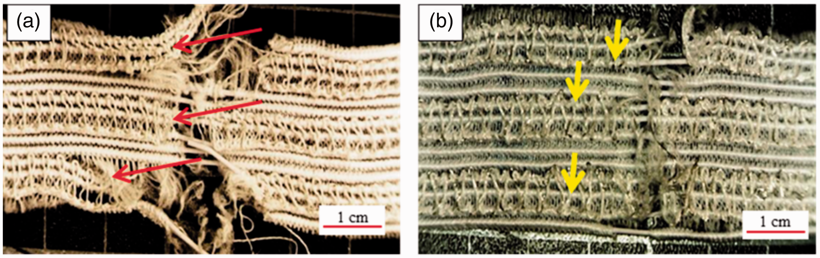
In sum, the conductive yarns that have high elongation (i.e. S-twisted yarn, D-twisted yarn, and S-wrapped yarn) result in an even fractured edge of the resulting conductive elastic knits. When a tensile force is applied to the knits, the conductive yarn elongates to the maximum, followed by the changes of knit pattern and then the local deformation of the warp yarn. The conductive yarns with high elongation will break before the knit pattern changes, and the knits do not exhibit local deformation of warp yarns (Figure 13(b)).
Effect of parameters on elastic recovery rate of conductive elastic knits
According to section ‘Effect of parameters on tensile properties of elastic knits’, the mechanical properties of conductive elastic knits are dependent on the structure of conductive yarns and knit patterns. The elastic recovery rate of the knits is thus evaluated using 70% length of elongation at break, thereby examining the effects of the two parameters. Figure 14 shows that regardless of whether it is wrapped yarns or twisted yarns and regardless of whether knit pattern, the knits have comparable elastic recovery rate, which is between 95 and 96%. General elastic knits are commonly composed of 40 D elastic yarns and have an elastic recovery rate of 70–80%. In this study, the extraordinary expansion enables the elastic knits with an elastic recovery rate of 95–96%. This result is because the rubber threads are not expanded to the expansion limit. The rubber threads of the warp yarns are thus not subjected to the component force exerted by the conductive yarns, and the influence on the elastic recovery rate is significant. The knit patterns also cause statistically significant difference in the elastic recovery of the conductive elastic knits of ST-5 CEK, ST-10 CEK, ST-15 CEK, DT-5 CEK, SW-20 CEK, SW-25 CEK, DW-20 CEK, DW-25 CEK, and DW-30 CEK (p < 0.05). Table 7 shows the results of the post hoc Scheffe's test: based on the significance, the influence of knit patterns on the elastic recovery can be ranked as A, C, D > B (ST-5 CEK), C, D > B (ST-10 CEK), and C > A (ST-15 CEK), B, D > A, C (SW-20 CEK), C > A (SW-25 CEK), A, B, C > D (DW-20 CEK), A, C, D > B (DW-25 CEK), and A, C > D (DW-30 CEK).
The elastic recovery of knits that are composed of (a) S-wrapped yarn, (b) D-wrapped yarn, (c) S-twisted yarn, and (d) D-twisted yarn in relation to knit patterns. Statistical analyses of elastic recovery rate. CEK: conductive elastic knits; DT: D-twisted yarns; DW: D-wrapped yarns; ST: S-twisted yarns; SW: S-wrapped yarns.

Effects of parameters on air permeability of conductive elastic knits
The air permeability of knits depends on the structure and thickness of fabrics as well as the type and specification of yarns [3]. Therefore, the specification of yarns and the structure of fabrics are two selected parameters whose influences on the air permeability of the conductive elastic knits are examined.
The control group is pure elastic knits without conductive yarns. Figure 15 shows that the air permeability of the experimental groups is higher than that of the control group (146 cm3/cm2/s). The knits exhibit local deformation where the conductive elastic yarns are knitted, as indicated in a yellow rectangle in Figure 16(a). The deformation forms pores that allow air to penetrate. When the knit pattern is specified, variations in the parameters of conductive yarns (i.e. twist number and the number of the PET filaments) do not have a significant influence on the air permeability. The presence of deformation is attributed to a high rigidity of conductive yarns. Conductive yarns are interlaid between two warp yarns, retracting the warp yarns and causing local deformation as seen in Figure 16(b). As a result, the air permeability of the conductive elastic knits increases where the conductive yarns are knitted.
Air permeability of conductive elastic knits that are composed of (a) S-wrapped yarn, (b) D-wrapped yarn, (c) S-twisted yarn, and (d) D-twisted yarn in relation to knit patterns. Stereomicroscopic images of the (a) back side and (b) front side of conductive elastic knits, where the regular distance between warp yarns is indicated in red rectangles, while the deformation of the knits is indicated in yellow rectangles.

Figure 16 shows that knits made of patterns B and D have a great amount of pores when they are expanded. However, when the knits shrink, the pore size is decreased as a result of the knit patterns being compressed by the shrinkage. In addition, Figure 15 shows that the air permeability of the knits is highly dependent on the knit pattern. Comparing to the control group, the experimental groups that are composed of knit patterns have local deformation and pores, which benefits the air permeability. However, regardless of knit pattern, the experimental groups have comparable air permeability. This result is ascribed to the fact that the knits are fabricated with the presence of a pre-tension force, which leads to the formation of pores between conductive yarns (Figure 17). When the pre-tension force is removed after the knit process, the conductive elastic knits shrink, which in turn decreases the pore size. The knit patterns also cause statistically significant difference in the air permeability of the conductive elastic knits (p < 0.05). Table 8 shows the results of the post hoc Scheffe's test: based on the significance, the influence of knit patterns on the air permeability can be ranked as A, B, D > C (ST-5 CEK), A, B, D > C (ST-10 CEK), B, D > C (ST-15 CEK), A, D > B, C (DT-5 CEK), A > D > B, C (DT-10 CEK), A > B, C, D (DT-15 CEK), C, D > A, B (SW-20 CEK, SW-25 CEK, and SW-30 CEK), D > B, C > A (DW-20 CEK), B, C, D > A (DW-25 CEK), and D > A (DW-30 CEK).
The front side of conductive elastic knits in terms of knit patterns a, b, c, and d. (a–d) are the expanded samples and (a’–d’) are the non-expanded samples. The deformation is indicated by red arrows and the pores caused by the expansion are indicated by yellow arrows. Statistical analyses of air permeability. CEK: conductive elastic knits; DT: D-twisted yarns; DW: D-wrapped yarns; ST: S-twisted yarns; SW: S-wrapped yarns.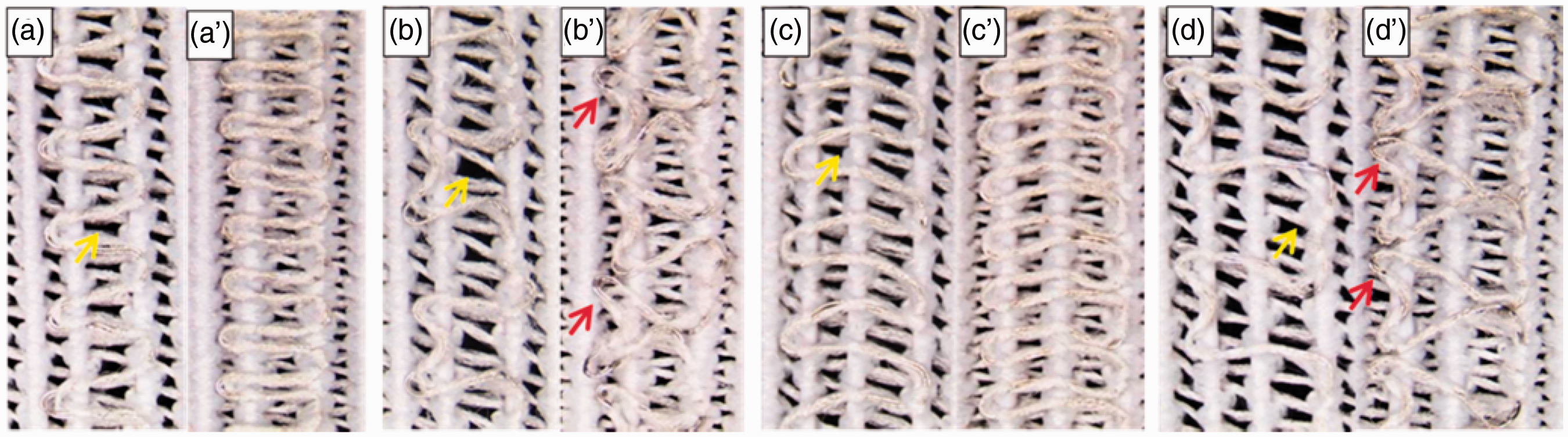

Effects of parameters on stability of electric circuits of knits
The metallic wires can be covered in PET filaments via twisting and wrapping processes. The wrapped yarns or twisted yarns can be formed into conductive elastic knits without difficulty. Incorporating different knit patterns may cause the exposure of metallic wires wherever the conductive yarns are sharply curved. Therefore, the electric circuit stability of knits is examined in terms of the twist number of conductive yarns and knit pattern.
There is a great variety of similar stereomicroscopic images, and 10 typical results are shown in Figure 18. Table 9 shows that conductive elastic knits that are composed of S-twisted yarns do not have well covered metallic wires, regardless of twist number of conductive yarns and regardless of knit patterns. As the metallic wires are not completely enwrapped in PET filaments (Figure 7), the S-twisted yarns in the knits thus have exposed metallic wires during the knit process, as seen in Figure 17(b’).
Ten typical results of the conductive elastic knits that are 70% expanded (first column) and non-expanded (second column). The LED that is not lighting shows a short circuit that is indicated by red arrows. Electric circuit stability of knits before/after expansion as related to the TPI of conductive yarn and knit pattern. Note: ○ shows that the knits do not have a short circuit, Δ shows that the knits have a short circuit when a conductive wire of the tester is compressed to contact them, □ shows that the knits do not have a short circuit when a conductive wire of the tester is compressed to contact them, and × shows the presence of a short circuit.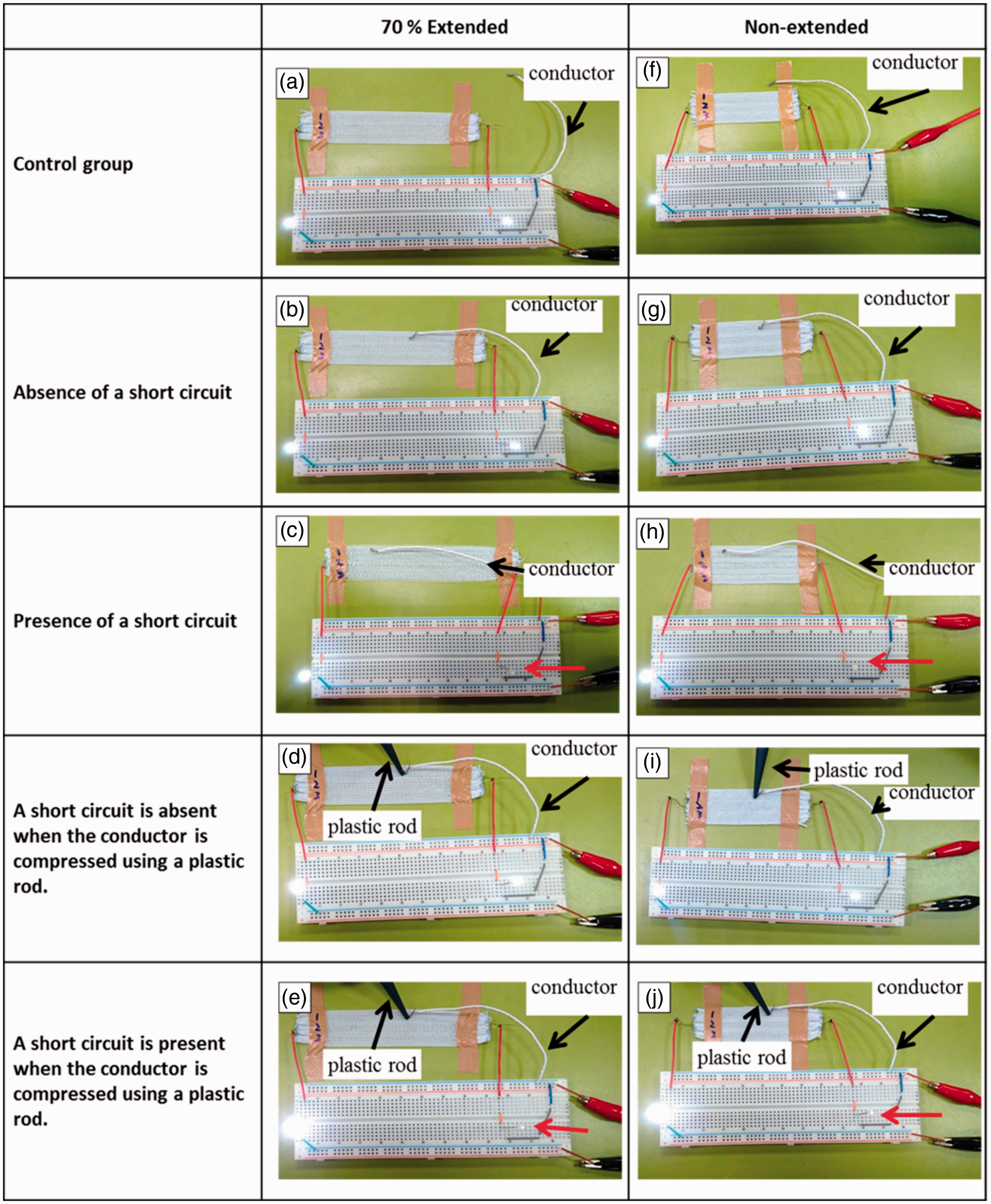
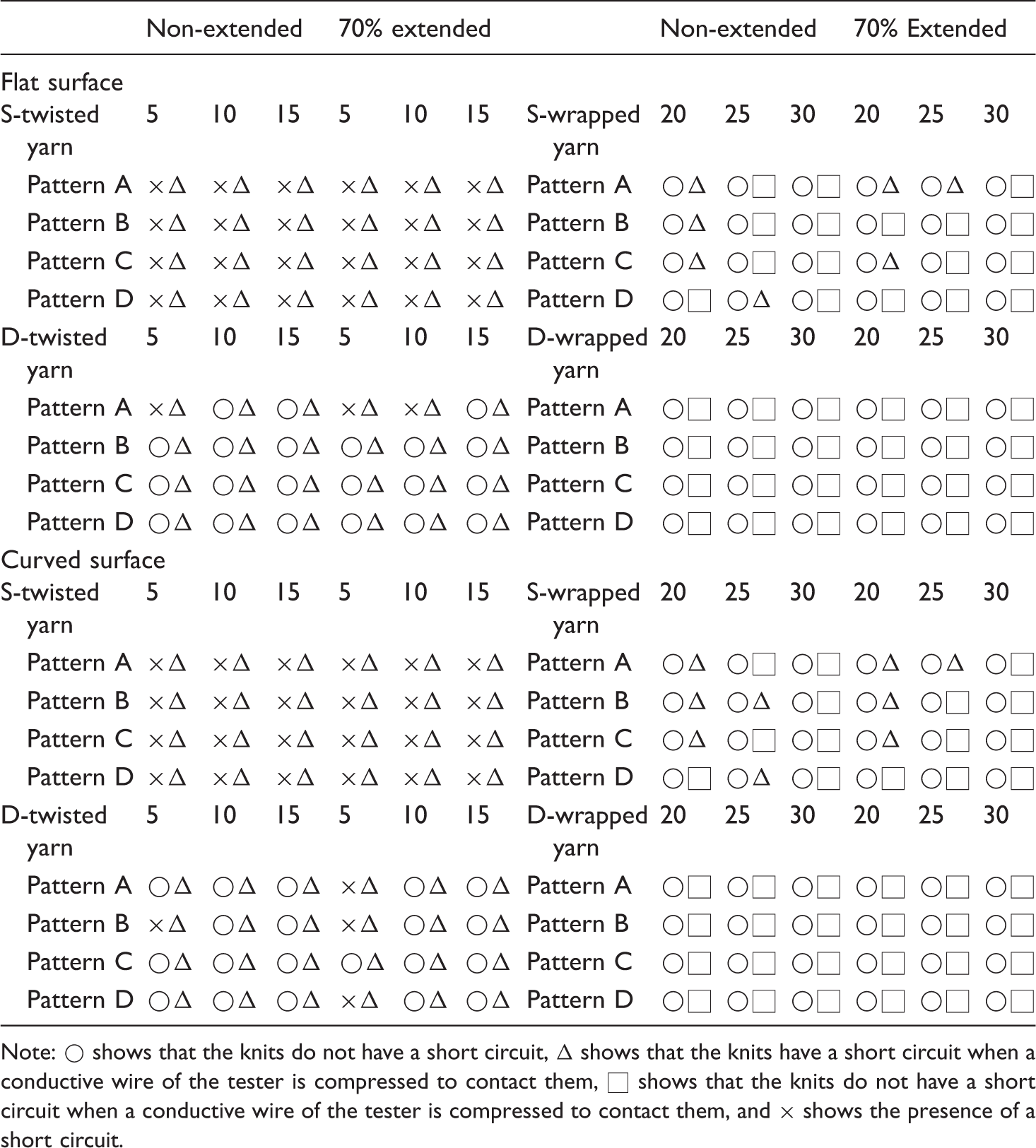
For the conductive elastic knits that are composed of D-twisted yarn, regardless of the twist number and regardless of the knit pattern, the knits have a short circuit when the plastic rod is used to keep the conductor in good contact with the knits. Without using the plastic rod, only three knits have a short circuit. D-twisted yarns are bent during the formation of knit pattern, which makes both PET filaments and metallic wires are exposed. Therefore, there is a possibility for the conductor to contact the metallic wire and cause a short circuit. However, compressing the conductor with a plastic rod ensures a good contact with the knits which definitely causes a short circuit.
For the SW CEK, none of the knits exhibits a short circuit when not using a plastic rod, whereas seven samples exhibit short circuit when using a plastic rod. The PET filaments and metallic wires are exposed as a result of the bending of S-wrapped yarns, and the amount of the exposed PET filament is higher than that of the exposed metallic wires, as such preventing the conductor from contacting the metallic wire, and the short circuit is absent. Furthermore, using a plastic rod makes the access to the metallic wires easier for the conductor, which then causes in a short circuit. Noticeably, for DW CEK, regardless of whether using a plastic rod or not, all the knits do not have a short circuit. Due to the compact enwrapping of two 150 D PET filaments, the metallic wires are tightly enwrapped and not exposed during the formation of knit pattern.
Basic electrical resistivity of the conductive yarns as related to different knit patterns.


The length of the extended conductive yarns of the pattern (a) A, (b) B, (c) C, and (d) D as related to the knit patterns.
The difference in knit pattern renders the conductive yarns with extension. However, the length of conductive yarns per unit length of the knits does not extended when the conductive elastic knit is stretched. As a result, regardless of whether the surface is flat or bent, the surface resistivity of conductive yarns does not change when the knits are stretched. Due to the excellent conductivity of the conductive yarns, there are no remarkable changes in their surface resistivity when the knits are compressed or stretched. The metallic wires used in this study are tin-plated copper wires have good anti-corrosion, and sustain surface resistivity after the washing of the conductive elastic knits. Finally, the test results of stability of electric circuits show that the resistivity of conductive yarns reaches 0.64 Ω/5 cm when the conductive yarns are exerted with electricity of 5.5 V and 0.020 A. The provision of electricity renders the conductive yarns with higher temperature, which in turn increases the electrical resistivity of the conductive yarns.
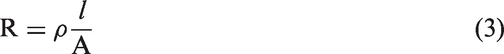
Figure 20 shows that after the abrasion measurement of the conductive elastic knits, there is a distinctive difference in the exposure of metallic wires. Groups that show the exposure of metallic wires include ST-5, ST-10, ST-15 CEK, and DT-5-A CEK (Table 11), and they exhibit a short circuit during the stability of electrical circuit test. Only DW-20-A, DW-20-C, DW-25-A, DW-25-C, DW-30-A, and DW-30-C CEK do not have exposed metallic wires after the abrasion test. In addition, D-wrapped yarns possess good protection, which is, however, inclined to different levels of damage. Patterns B and D have more convex bending conductive yarns and the convex spots are damaged when in contact with the calibrase wheel (Figure 20(a)).
The surface morphology after the abrasion test, showing (a) exposure and (b) no exposure of metallic wires. The surface morphology of metallic wires before/after the abrasion test. CEK: conductive elastic knits; DT: D-twisted yarns; DW: D-wrapped yarns; ST: S-twisted yarns; SW: S-wrapped yarns. Note: “Y” means the exposure of metallic wires and “N” means no metallic wires are exposed.

Conclusion
This study investigates the physical properties of the conductive elastic knits in terms of twist numbers of the conductive yarns as well as knit patterns. Different twist numbers are used for a primary purpose of insulating the metallic wires and a secondary purpose of improving the mechanical properties of the yarns. The test results show that the twisted yarns have higher mechanical properties but a lower enwrapping level of metallic wires than the wrapped yarns. Moreover, the parameters of conductive elastic knits are examined in order to have an efficient production and stabilized electric circuits. The test results indicate that DW CEK series have good tensile properties, air permeability, elastic recovery rate, electrical resistance, and stabilized electrical circuits regardless of whether it is a flat or curved surface. Only a few groups have good abrasion resistance, including DW-20-A, DW-20-C, DW-25-A, DW-25-C, DW-30-A, and DW-30-C. In particular, DW-20 CEK is determined to be the optimal based on the aforementioned properties, production cost, and knit pattern.
Comparing to the conductive Polydimethylsiloxane (PDMS) composites (the conductive PDMS composites made using the mold casting technique), the conductive elastic knits proposed in this study have a porous structure, and thus have good air permeability of 150–180 cm3/cm2/s. The elongation of conductive PDMS composites is 10–25% while that of the conductive elastic knits is 95–96%. For the fatigue test, a previous study discovered that the conductive knits made of conductive yarns could bear 1.5 m times [4], which is much higher than that of conductive PDMS composites (0.02 m times [13]).
The proposed conductive elastic knits are flexible and can stay next to the skin of the wearers without limiting the mobility. Therefore, they can also be incorporated with sensors to form wearable electronic textiles that are used in far infrared therapy and health monitoring.
Footnotes
Declaration of conflicting interests
The author(s) declared no potential conflicts of interest with respect to the research, authorship, and/or publication of this article.
Funding
The author(s) disclosed receipt of the following financial support for the research, authorship and/or publication of this article: The authors would especially like to thank Ministry of Science and Technology of Taiwan, for financially supporting this research under Contract MOST 105-2622-E-166- 001-CC2 and MOST 106-2632-E-035-001.