
Abstract
Three-dimensional preforms have been developed in order to remedy and minimize the out-of-plane damage caused by 2D structures. Several researches have been done on more complex structures which have more interesting mechanical characteristics through-the-thickness. A wide spectrum of 3D textile technologies encompassing weaving, knitting, stitching, z-pinning, tufting, etc. is used to manufacture through-the-thickness reinforced materials. This kind of reinforcement aims to achieve a balance between the in-plane and out-of-plane properties. Recently, tufting shows more opportunities to develop through-the-thickness reinforcements especially with the advances in devices from manual to fully automatic. In literature, the mechanical behaviour of tufted composites has been one of the main subjects, however, few studies outline the mechanical behaviour of dry tufted fabrics. Dry stage is an essential step to understand the influence of through-the-thickness reinforcement and the formability of multilayer preforms. In this context, the present paper reviews the various technologies of through-the-thickness reinforcement as well as the microstructural defects related to both the impregnation and the kind of reinforcement. Also, this work highlights the mechanical performance of tufted 3D structures at dry and composite scales.
Introduction
To meet increasingly demanding environmental targets (as for example, of a 75% reduction in CO2 emissions and a 90% reduction in NOx emissions, by 2050) with respect to the year 2000 baseline [1], the weight reduction will continue to play a key role especially by using composite materials [2]. Composite materials are consequently widely used in aeronautics, space and defence industries. In essence, the key to the successful use of composites in these load-bearing situations depends on how to transfer the loads without inducing tensile stresses in the composite which are transverse to the fibres as these cause delaminations [3]. The need for affordable composites that have significantly improved through-thickness strength and interlaminar damage tolerance intensified the development of a wide variety of textile preforms [4]. A variety of 3D fibre composites have been developed to overcome some of the problems that are inherent with conventional polymer laminates, such as their low delamination resistance and poor impact damage tolerance [5–8]. Especially the through-thickness fibres, which are given the general term of z-binders, are used to provide 3D fibre composites with higher delamination fracture toughness and impact damage tolerance than conventional laminates [9–11]. In order to obtain 3D preforms, the through-thickness fibres can be inserted using a variety of textile techniques which include 3D weaving, stitching, tufting, 3D-knitting and 3D-braiding. Besides, thin metallic pins can be inserted along the thickness direction instead of the through-thickness yarns. This is known as Z-pinning [12, 13]. Three-dimensional fibre composites manufactured from 3D-woven preforms are the subject of a lot of numerical and experimental studies [6–8, 14–21] for their application in high-tech industrial domains, for instance fan blades developed by Snecma [3, 8, 22]. From a large data base collected in literature Mouritz [10] presented the in-plane and out-of-plane mechanical properties of 3D-fibre composites manufactured by different textile technologies quoted previously. Comparisons to conclude on the best textile technology to reinforce through-the-thickness remain very difficult due to the numerous economic, technical and certification issues to consider.
Few results concern tufted 3D-fibre composites and their mechanical properties which are essentially published in [23–33]. Recent studies presented by Pappas et al. [34, 35] and Najafloo et al. [36] outline the influence of tufting parameters on the mechanical performance of the final structure.
The main purpose of this paper is to compare the tufting technology to other technologies of reinforcement and to improve the understanding of the mechanical behaviour of tufted preforms. Based on the literature, the first section describes the three main reinforcement technologies encompassing Z-pinning, tufting and stitching. The second section describes the microstructural damages and defects at different scales. The last section concerns only the mechanical performance of 3D-tufted structures at both dry and composite scales.
Reinforcement technologies
In general, the development of composite structures with high mechanical performance depends on the reinforcement architecture and on the manufacturing process. The choice of the reinforcement, the experimental and numerical approaches leads to the optimisation and the control of thick structures with complex shape.
In literature, the classification of 3D structures is based on different criteria and parameters such as fibre orientation and placement of yarns within the preform. Figure 1 shows a simple classification of 3D reinforcements.
Classification of 3D reinforcements.
Several studies have been done about the one-shot manufacturing [9, 37]. However, the through-the-thickness reinforcement has been well developed during the last decade. Therefore, the present paper focuses only on the through-the-thickness reinforcement technologies.
In fact, through-the-thickness technologies represent an efficient method to manufacture complex shape structure with great mechanical properties particularly delamination resistance and impact damage tolerance. Also, these kinds of reinforcement have the potential to develop, at lower cost, structures with high stiffness.
In the present section, the three most widely used technologies of through-the-thickness reinforcement namely Z-pinning, stitching and tufting are examined. Advantages and drawbacks of each technology are also illustrated.
Z-pinning
The Z-pinning technology, also known under Z-fibres reinforcement, is the insertion of rigid rods or pins, which act as fine nails, to lock the laminate plies together [12].
The Z-pinning process is a simple and reliable method where it requires the placement above the stack of foam containing the pins. The upper face of the foam is then swept by an ultrasonic impactor which provides the well insertion of pins into the laminate. Then, the excess of Z-pin remaining in the preform is sheared away and the collapsed foam is removed.
Figure 2 shows the sequence of several steps of the Z-pinning process that should be done consecutively to ensure a uniform and homogeneous assembly of the laminate layers.
Z-pinning technology [12].
Z-pins are made with high stiffness and high material strength such as carbon/epoxy, titanium or steel and the diameter of pins is about 0.2–1.0 mm [12]. As the rods are rigid, this method makes it possible to reinforce laminates already pre-impregnated. Figure 3 shows the typical size of rigid rods and pins inside the composite structure.
Illustrations of (a) the size of a typical Z-pin and (b) Z-pins inside a prepreg composite [12].
The resistance to delamination of this kind of composites depends not only on the volume fraction but also on the diameter of the inserted pins. The volume fraction is relatively low in order to improve considerably the mechanical performance of the laminate where the volume ratio is about 0.5–4.0% which is approximately equivalent to 8–70 Z-pins/cm2 [12].
Another use of the Z-pinning technology is to reinforce stiffener-to-skin joint where Cartié et al. [28] outlines the manufacturing process and the mechanical behaviour of T-joints reinforced by Z-pinning. A rigid carbon/BMI resin rods, having a diameter of 0.28 mm, were inserted as pins in order to reinforce pre-impregnated layers as shown in Figure 4.
Illustrations of (a) Z-pinning insertion process and (b) hand held ultrasonic insertion unit [28].
Stitching technology
Stitching technology is one of the most efficient technology of through-the-thickness reinforcement that has been widely reviewed by Mouritz et al. [9], Tong et al. [37] and Dransfield et al. [38]. It is based on the sewing process where a dual-threading system (bobbin & needle threads), as shown in Figure 5, makes the seam by forming loops and knots through the laminates or fabric plies.
Illustration of the stitching technology [37].
Stitching involves the insertion of high performance yarns, such as carbon, glass, Kevlar or any other high strength fibrous, through the laminate thickness in order to improve the interlaminar and delamination properties. In fact, the stitch densities and fibre properties influence significantly the mechanical characteristics of the final structure.
Typically, there are three different types of stitching techniques depending on the position of the binder threads within the preform:
– Chain stitch: the binding of the loops is carried out at the surface laminate via a single thread. The chain point can be easily unravelled by pulling from the last to the first stitch point. This sewing mode is generally used to create temporary stitch points. The principle of the chain stitch is summarized in Figure 6(a). – Lock stitch: this type of sewing is the most commonly used. Loops are created in the middle of the preform via a needle thread as shown in Figure 6(b). It requires a double access to the laminate (both bottom and top). The bobbin and needle threads are linked inside the preform which may generate a high stress concentration and resin rich areas. – The position of the loops inside the laminate, and particularly in the middle of the preform, is a major disadvantage, which cause microstructural damages such as fibre crimping and yarn distortion. – Modified lock stitch: it is well known as the stitching type which causes the least damage and stress concentration of the laminate. The intersection is carried out at the top of the preform by varying the tension between bobbin and needle threads as shown in Figure 6(c). This technique is the simplest sewing technique to be realised. It is particularly used for sewing edges.
Illustrations of (a) chain stitch, (b) lock stitch and (c) modified lock stitch [39].
One of the main advantage of the sewing technology is the ability to stitch both dry and prepreg fabric. Stitching can also be used to manufacture complex three-dimensional shapes which improves the performance through-the-thickness. Moreover, the stitching technique presents a great deal of flexibility in the arrangement of through-the-thickness reinforcement by varying the sewing parameters (stitching density, pattern, stitching thread, etc.) [37].
However, the creation of knots within the laminate may cause misalignment and breakage of the binder threads.
Several studies [40–42] have been carried out on the sewing machines in order to develop new concepts which require only-one-side access to the preform to avoid defects and damages of stitched structures. Among the advanced stitch techniques, the one-side-stitching (OSS) technology has been developed to assemble laminates where the access into the preform is limited to one side (Figure 7).
Illustrations of (a, b) OSS technologies and (c) blind stitch [26].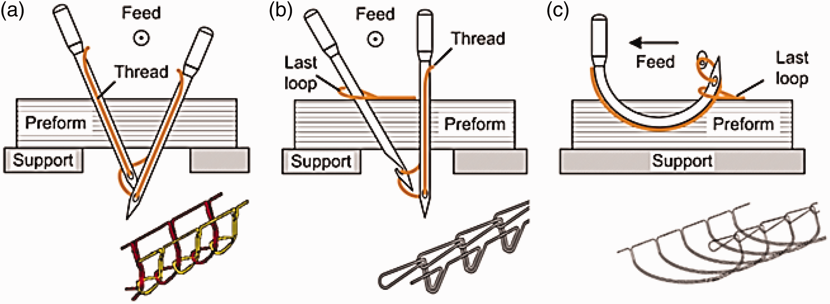
For the OSS technology (Figure 7(a, b)), the formation of loops is carried out by a hook, inserted at 45°, which ensures the recovery of the previous loop and the formation of the following loops. However, the blind stitch, shown in Figure 7(c), requires a curved needle that enters and returns from the same side of the preform. Only one thread is required for the blind stitch.
Tufting technology
Previously, the tufting technology was used only for carpet and warm garments manufacturing. Now, it has become one of the most efficient technologies for through-the-thickness reinforcement. Tufting process represents the simplest one-sided stitching technology as illustrated in Figure 8(a). It is specifically designed for the dry preform /liquid composite moulding process route.
Illustrations of (a) tufting technology and (b) partial & global-tufting [43].
The insertion of tufts is carried out via a hollow needle without generating any tension at the surface of the laminate which avoids the shearing and crimping aspects. The loops are not tied or interlocked and the tufting yarns remain in position due to the natural friction between the fabric and the thread. This technology requires only one access to the preform, which makes it ideally suitable for local through-the-thickness reinforcement. The threads can be fully inserted, where the tufts exceed the depth of the preform and the loops are visible at the bottom of the fabric or applied to a partial depth through the preform thickness where the loops are fully retained within the laminate (Figure 8(b)). In this context, Préau et al. [29] assert that ‘partial-tufting’ is an efficient technique since it makes it possible to avoid the creation of resin pocket and makes mechanical modelling much simpler.
The principle of the tufting technology is more detailed in Figure 9. It should be noted that tuft threads can be inserted orthogonal to the preform surface or angled as shown in Figure 9(c).
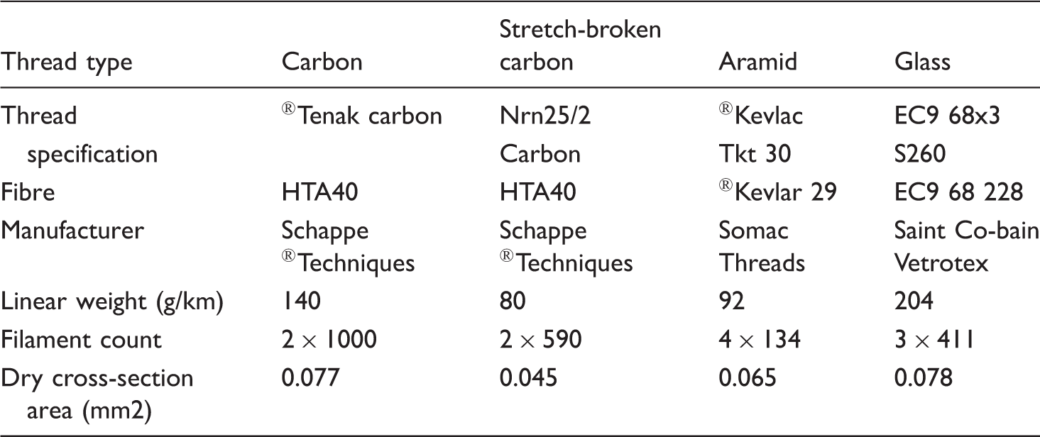
Tufting process [26].
Different types of tufting thread [26].
Special needles (Figure 10) have been designed with an inclined hole to facilitate the insertion of thread loops into the dry preform. The choice of the needle depends on the thickness of the preform as well as the tufting yarn.

The performance of tufted preforms is highly influenced by the tufting pattern. Figure 11 shows an example of tufted preforms in square spiral and circular spiral where the tufting yarn is continuous throughout the preform.
Tufting pattern (a) square spiral and (b) circular spiral [44].
Currently, the development of the tufting device represents a major topic for several studies [23, 24, 30]. The first devices (e.g. KSL KL150) are mechanically operated by a motor connected by belts which simultaneously control the needle device and the presser foot. This type of machine can produce up to 500 tuft/min within the preform up to 5 mm thickness [26]. The developed models (e.g. KSL RS522) have abandoned the use of a single motor for a more adaptable mechanism where the needle and the presser foot are independently controlled by three motors. This kind of device can tuft rigid and thick preform (up to 10 mm thickness).
In addition to the geometry and the tufting pattern, the precision of the thread insertion determines the effectiveness of the reinforcement. For example, the Kuba KR100-HA device has an accuracy of ± 0.05 mm [26]. These machines are illustrated in Figure 12.
(a) Robot Kawasaki FS 20_KSL KL150 and (b) robot Kuka KR 240-2_KSL RS522 [26].
Figure 13 presents the automatic equipment developed in our laboratory in order to handle tufting structures. The present device is equipped with the following elements [25]:
– Tufting device can move along the x and y axes. It is made with a tufting needle which is connected to a pneumatic jack, which makes it possible to control the tufting deepness. The choice of the needle depends on the type of the preform as well as the characteristics of the tufting thread. – Presser foot device is controlled by another pneumatic jack allowing both the attachment of the preform and the application of a pressure during the tufting process.
– Feeding device provides the tufting thread with a certain length and tension. – A mobile framework which allows the movement of the various equipment.
Tufting device (ENSAIT-Gemtex) [25].

It should be noted that the choice of the most suitable foam is an essential parameter for the proper handling of the tufting procedure and the tuft loops. Polypropylene or silicone foams are the most widely used [26].
Microstructural defects of 3D reinforced structures
The textile materials undergo several stresses which can weaken and degrade the mechanical properties of the final structure (e.g. tension, friction, fibre breakage and fibre crimping).
In fact, the creation of a various types of microstructural defects may happen during the manufacturing process encompassing fibre misalignment and breakage of the in-plane and Z-binder threads as well as the creation of resin pockets [37]. These damages may generate a large reduction of the in-plane properties where Lee et al. [45] highlight a significant decrease of the tensile and failure strengths due to the through-the-thickness reinforcement.
In the present section, the influence of the through-the-thickness reinforcement on the textile structure and the impregnation damages are highlighted.
Damages related to the 3D reinforcement
Through-the-thickness reinforcement can cause microstructural damages due to the needle penetration. The insertion of a binder yarn in the Z direction may lead to a distortion of the different layers as well as breakage and crimping of the binder threads. Figure 14 summarizes some of these defects obtained in a non-crimp-fabric (NCF).
Damages obtained in NCF structure [46].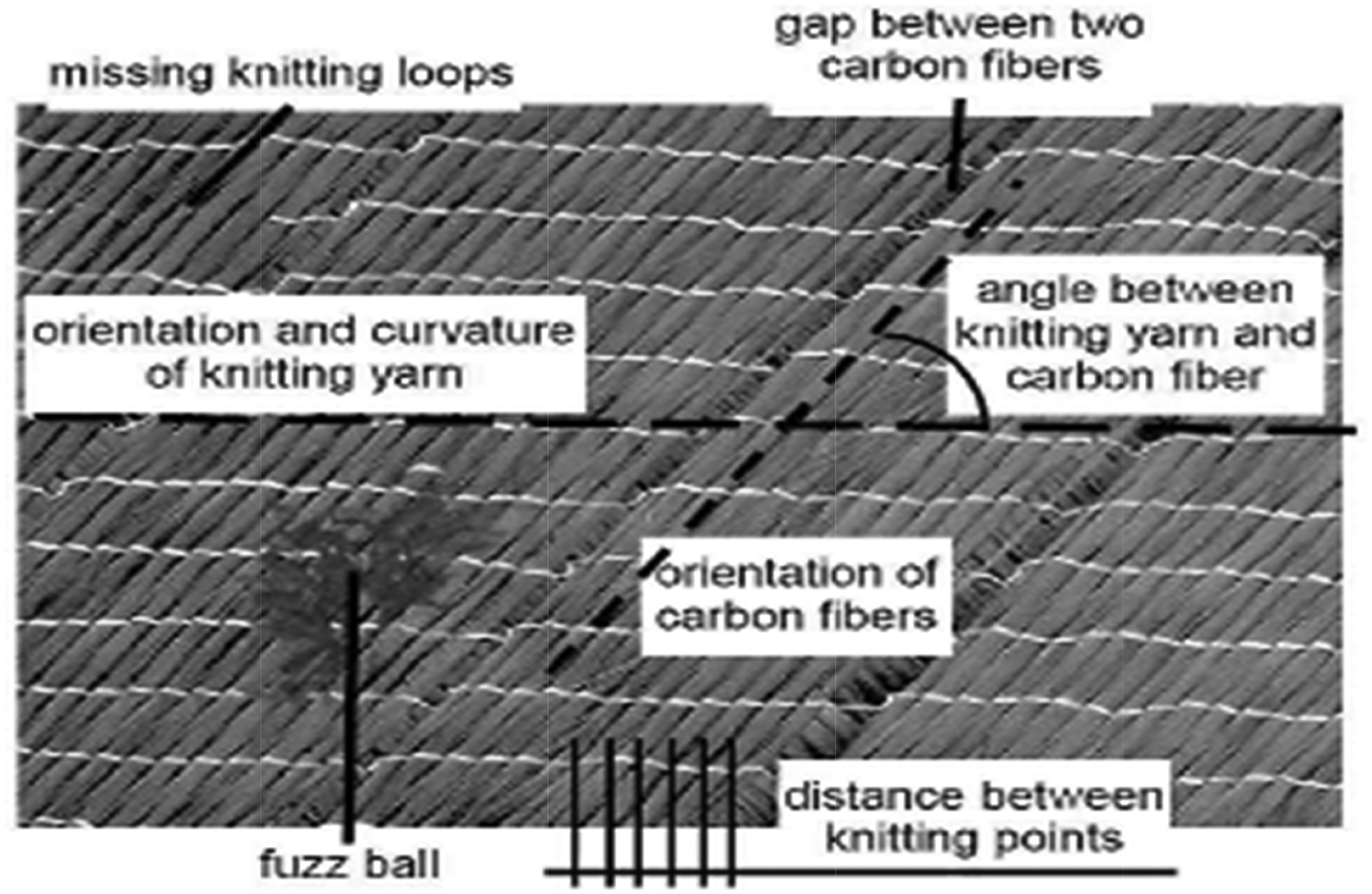
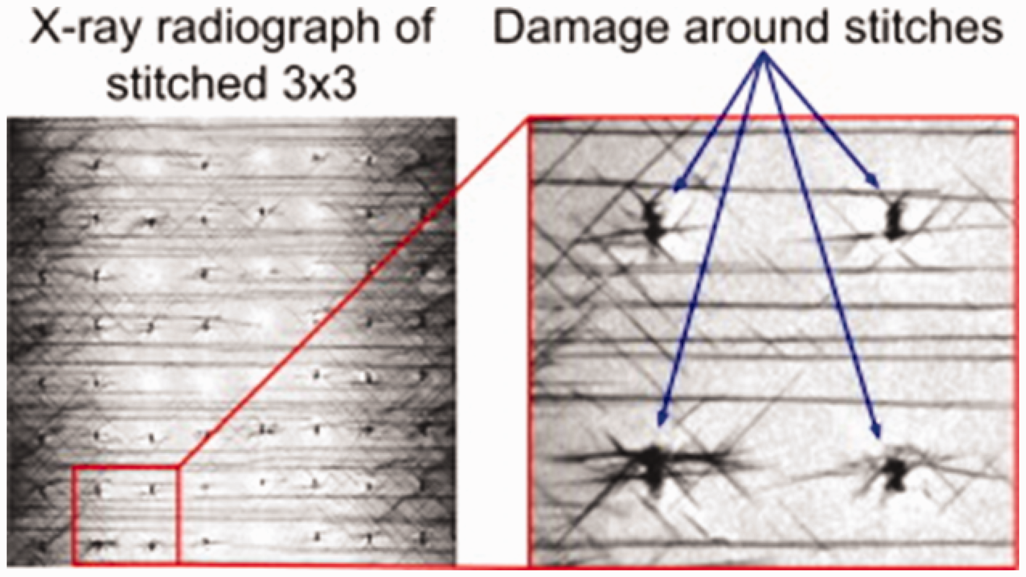
The other technologies of reinforcement through-the-thickness, namely: Z-pinning, stitching and tufting, may present a specific damage related to the parameters associated to these technologies. One of the most common defects of these technologies is the lateral spreading of in-plane fibres in the plane of the preform [12, 47]. The crimping defect is caused by the friction and the tension generated within the laminate due to needle or pin penetration. Figure 15 illustrates the damages related to Z-pinning technology while Figure 16 presents the defects resulted from the stitching process.
Damages around stitched composite [48].
Similar to conventional stitching and Z-pinning, the tufting technology presents some damages due to the needle penetration within the laminate where Treiber [33] illustrated several types of tufting defects. The main damages are thread crimping and splitting, particularly at the entry point of the needle. Figure 17 shows the misalignment or deviation of the several layers due to the deflection and the breakage of binder threads due to the penetration of the tufting needle.
Tufting damages. (a) Carbon thread splitting; (b) crimping thread at needle entry point; (c) tufting seam deviation in UD layup [33].
Another major damage, related to the tufting process was presented in Treiber [33], is defects of loop formation tufting without thread pretention lead to an insufficient tensioning of the surface seams (Figure 18).
Illustrations of (a) insufficient tensioning of tufting seams and (b) fabric damage due to the needle penetration [33].
Impregnation damages
Regarding the impregnation damages, through-the-thickness reinforcements may influence the properties of the final composite and particularly the volume fraction of fibres which is a “key” parameter for a better impregnation of the preform.
In this context, Mouritz [12] assert that the insertion of pins through laminates thickness may generate some microstructural damages such as fibre crimping and waviness which reduce significantly the fibre volume content and promotes the creation of resin-rich areas [9, 12, 49]. Figure 19 illustrates some microstructural damages within Z-pinned composite.

For the stitching technology, the penetration of the needle may cause specific localised damages that decrease the in-plane mechanical performance of reinforced structures such as tension, compression and shear properties.
The fact that the stitching technology requires a dual-threading system in order to make loops and knots which begets a significant weakness in the mechanical properties of the final structure. Figure 20 outlines the main defects resulting from the sewing process.
Illustrations of stitching damages (a) crimping of in-plane fibres, (b) misalignment of in-plane fibres, (c) distortion of through-thickness threads and (d) creation of resin pocket. x1, x2 in-plane directions and x3 through-thickness direction [39].
As described previously, the presence of through-the-thickness yarns influences significantly the impregnation process as well as the creation of microstructural damages within the laminate. In the case of tufted structures, a waviness and distortion of binder threads have been visualized during the manufacturing process of the composite structure. Figure 21 presents disorientation of tufted threads during the impregnation process.
Distortion and disorientation of tufting threads [43].
In addition to the microstructural damages caused by the tufting process, non-homogeneous areas can be obtained where Dell’Anno et al. [26] highlight the presence of both well impregnated and dry zones (without resin) due to the bad impregnation of the preform. Nevertheless, the bad impregnation may lead to an increase in the thickness of the tufted regions especially in the cured part as shown in Figure 22.
Illustrations of (a) dry areas on a macroscopic scale and (b) increase in thickness in the tufted regions [26].
Figure 23 illustrates the resin pockets obtained during the impregnation process of tufted structures. This defect is due to the wrinkling and crimping of tufted yarns. These defective areas reduce significantly the mechanical behaviour of the preform which will be more detailed in the following chapter.
Illustration of resin pockets obtained during the impregnation of tufted structures [33].
Mechanical performance
Several researches have been carried out in order to highlight the mechanical performance of through-the-thickness reinforced structures. In literature, the mechanical performance of through-the-thickness reinforced composites is more described than the mechanical behaviour of 3D reinforced fabrics (before the impregnation process).
The mechanical properties of 3D reinforced composites are extremely influenced by numerous factors:
– Reinforcement parameters: fibre nature, yarn characteristics, reinforcement architecture, reinforcement pattern, thickness, number and orientation of layers, etc. – Parameters related to the resin used: nature, flowing, viscosity, etc. – Manufacturing parameters: temperature, pressure, duration and process (injection/infusion/thermo-compression). – Parameters specific to composite structure: thickness, volume fraction, porosity, etc.
Many studies [14, 15, 49–56] outline the mechanical behaviour of 3D reinforcement composites by numerical approaches, in particular by finite element. These studies, generally based on simplified methods and approaches, make it possible to overcome the complexity of 3D architectures. The present paper focuses only on the experimental results where in-plane and out-of-plane mechanical performances of through-the-thickness reinforced composites are described. Also, few researches already done on the reinforcement scale will be presented in the following section.
Composite scale
Mechanical properties in-plane of the laminate
Numerous researches have studied the mechanical behaviour of 3D tufted composites. Klopp and Moll [41] highlight the mechanical behaviour of tufted composites where a comparison between various architectures (UD, NCF, and Twill fabrics) of 3D carbon structures tufted with two different tufting densities (0.5% and 2%) is established in order to highlight the influence of tufting reinforcement on the mechanical behaviour of the final structure (Figure 24). These results show that the tufted composites present a tensile strength and rigidity lower than the untufted structures. Furthermore, the mechanical behaviour depends on the type of laminate where the mechanical behaviour is quite different at high strains.
Stress–strain curves of tufted composites [33].
Shear stiffness of tufted structures [33].
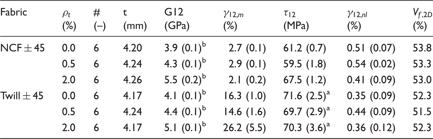
aDetermined at
bDetermined for
Numerous studies have been carried out in order to characterise the mechanical behaviour of tufted composites. For example, Dell’Anno et al. [23] have tested samples made from woven carbon tufted with glass or carbon thread, using the resin transfer moulding (RTM) process for composite manufacturing. They record a reduction of 10% on the tensile strength of the tufted sample where the initial slopes are similar, giving the same Young’s modulus. However, at a strain of 0.35%, they highlight a deviation from the linearity as shown in Figure 25(a). This reduction was explained not only by the fibres breakage and misalignment due to the needle penetration but also to the presence of resin pockets and voids around the tufts (Figure 25(b)). Moreover, De Verdiere et al. [32] reveal a reduction of the in-plane properties, about 10–15% in both tension and compression behaviour of tufted NCF composites.
Illustrations of (a) tensile behaviour of untufted and tufted samples and (b) resin pockets and impregnations defects in tufted composite [23].
De Verdiere et al. [32] assert that the tufting technology reduces the in-plane stiffness of material due to the presence of resin rich zones and fibre crimping. In the other hand, they prove that the presence of tufts leads to an increase of the mechanical properties in the bias direction of NCF composites which they record an increase of both tensile and compressive strength. The main finding of both studies [23, 32] is that through-the-thickness reinforcement, precisely the tufting technology, presents a compromise. It is quite logic to note a decrease of the in-plane properties due to the presence of tufts and obviously a higher performance on Z direction. Thus, a detailed study of all parameters related to the tufting device, the textile structure as well as the manufacturing of composites will be more efficient to achieve a balance between the in-plane and out-of-plane properties.
The following results of the in-plane mechanical behaviour of through-the-thickness reinforced structures lead to these main conclusions:
– Through-the-thickness reinforcement tends to suppress delamination and raise strength, but it can cause a reduction of the stiffness and fracture resistance in the in-plane of the laminate due to fibre breakage and misalignment. The stiffness is more stapled in the case of Z-pinning reinforcement. – The few studies conducted on planar shear behaviour appear to show a significant contribution of through-the-thickness reinforcement.
Mechanical properties out-of-plane of the laminate
Many studies have been done on 3D weaving composite [29, 38, 39, 57–62] showing better resistance to interlaminar shear, hence, a greater thickness resistance for 3D fabrics. Indeed, the 3D woven composites generally have a very low shear stiffness which ensures a good formability of the structure. However, this behaviour may decrease considerably the anisotropy as well as the elastic behaviour of the material, which make the modelling more complicated.
Several researches [12, 28, 47, 63–77] have been carried out on the Z-pinning technology shown that the addition of ‘pins’ through-the-thickness of the laminate improves the mechanical performance of the final structure. Preforms reinforced with Z-pinning present high delamination toughness, under different shear modes: I, II and mixed I/II, which increase damage tolerance and impact resistance [12, 63, 65].
Mouritz [12] asserts that Z-pinning technology leads not only to an increase of through-thickness elastic properties of laminates but also to higher impact strength due to its low damage rate.
Regarding the mechanical behaviour of stitched composites, they present a great in-plane and through-the-thickness strength. In addition, stitched composite has shown a high improvement in the interlaminar fracture toughness under mode I and II [38, 60]. Also, these structures present a high impact performance [38, 61, 78, 79] and fatigue resistance [62].
Among the most performed tests on the tufted composite is the compression after impact (CAI) behaviour where in papers [23, 32], they assert that the presence of tufts leads to a significant increase in the resistance of delamination which generates higher CAI performance. For example, Dell’Anno et al. [23] record a raise in the CAI strength by 25% and 27% in the presence of tufted carbon or glass threads, respectively.
Furthermore, Préau et al. [29] have studied the mechanical behaviour of tufted composites where they mention a significant decrease of the in-plane characteristics, particularly, the tensile and bending behaviours due to the presence of resin rich area. However, the tufting specimens show a significant increase of the interlaminar fracture toughness (mode I). Moreover, Treiber [33] highlighted the mechanical properties of tufted carbon fibre/epoxy composite and the results show a great increase especially in the delamination resistance, by a factor of three, within the laminate. One of the most important points presented in the paper [33] is the concept of the transverse elastic modulus (90) where it shows an increase by 7% and 45% for 0.5% and 2% areal tuft densities, respectively, for the unidirectional composite. The main reason of this increase appear to be the locally increased fabric density around the tuft and the addition of tufting thread and loops parallel to the loading direction. In the same context, Henao et al. [24] have also focused on the compression and bending properties of tufted sandwich where they highlight an increase in both bending and edgewise compression strength as a result of adding tufted yarns. For instance, the increase of the compression strength was about 25.23%, 13.22% and 7.54% for tufting spacing values of 5 mm, 10 mm and 15 mm, respectively. Regarding the bending behaviour, they assert an increase in the failure load for the tufted specimens over 106% in comparison with the non-tufted ones. However, Hartley et al. [27] have studied the crushing performance of tufted sandwich structures where they reveal an increase in the crush strength between 11% and 19%. Indeed, the increase of the number of tufts generates a significant enhancement of the crushing performance about 25% in comparison to the untufted sandwich. Nevertheless, the variation of the loop length appeared to have a negligible effect on the loading response.
Dry scale
The mechanical behaviour at the dry scale has a significant influence on the processing parameters such as porosity, permeability and obviously the mechanical properties of the final composite. Therefore, a detailed study of the preform performance leads to a good understanding of the mechanical behaviour of the final structure. In this context, Saboktakin [31] has studied both tension and compression behaviour of tufted twill woven fabrics. The tension test shows that the tufted preforms present a stronger deformation resistance where the maximum load of tufted structure is greater than the untufted one, contrarily to the failure displacement. The curve load/displacement can be divided into four specific regions: firstly, the crimp region where the load increases slightly follows the increase of the displacement due to the fibre breakage, followed by an elastic region where the curve present a linear slope. The tensile behaviour exhibited a nonlinear phase between the elastic region and ultimate strength point (peak point) followed by the post-failure region. However, the compression test shows a similar behaviour of tufted and untufted fabrics where both curves present three regions: a first linear part generated by the fibre crimping and the reduction of porosity within the structure, an exponential part related to the bending of woven fibres and tufting yarns and the final linear zone stand for the total compression of the preform. Saboktakin [31] has demonstrated that the compression behaviour is widely influenced by the tufting technology where an increase of the fibre volume fraction was noted due to the augmentation of the compaction load.
As detailed in the introduction, the present paper highlights the mechanical behaviour of tufted structure at the dry reinforcement through the preforming test on the basis of the results presented in Liu et al. [25]. The experimental forming with a hemispherical punch is performed in a specific device as shown in Figure 26. This equipment allows to analyse the double-curved shape of manufacturing with a given textile reinforcement in different conditions. The device is equipped with four pneumatic jacks applying an adjustable pressure on the blank-holder. Several parameters can be calculated from the stamping test such as the punch force, material draw-in, inter-layer sliding and wrinkles. It should be noted that the reinforcement fabric was an E-glass plain weave composed of four layers [±45°, 0°/90°]2 tufted with a carbon thread.
Illustrations of (a) preforming device and (b) main dimensions of forming device [25].
The experimental data presented in Liu et al. [25] show that the punch force increase as a function of the tufting density where they record a significant increase of the maximum punch force (≈33%) for a tufting spacing of 5 mm (Figure 27(b)). Thus, the increase of the tufting density may lead to an increase in the rigidity of the preform. However, the graphics of the material draw-in present an extremely different behaviour where it decreases following an increase of the tufting density (Figure 27(a)). Furthermore, they highlight the forming defects following the insertion of tufting yarns, particularly, the wrinkling aspect. It was observed that the preforms having a tufted spacing about 5–10 mm present the most regular structure and the fewer number of wrinkles, consequently, the increase of the tufting density may lead to a reduction in the number and the size of wrinkles (Figure 28).
Illustrations of maximum (a) material draw-in and (b) punch force [25]. Wrinkling aspect in (a) untufted structure, (b) tufted 10 mm and (c) tufted 5 mm [25].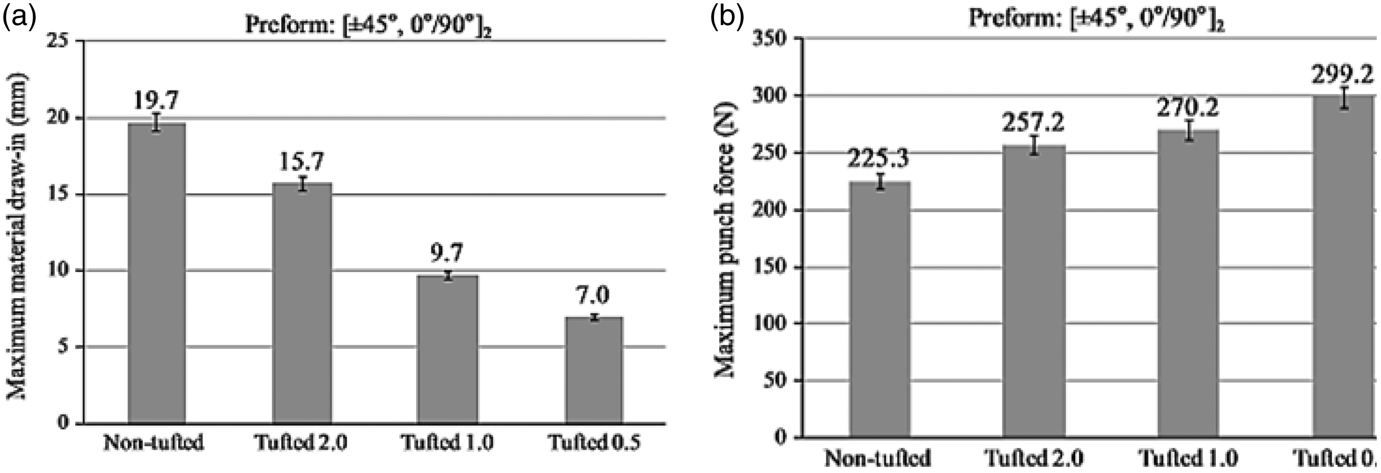

One of the most important points studied by Liu et al. [25] is the influence of tufting density on the inter-layer sliding during the forming process where they notice a big slippage of 19.7 mm for non-tufted structure in comparison to the tufted ones, especially, for the specimen having a tufting spacing about 5 mm, the inter-layer sliding is negligible (≈0.2 mm) where the four layers deformed in the same way. Subsequently, the increase of the tufting density generates a reduction in the inter-layer sliding during the preforming test.
Conclusion
This paper has presented an overview of published researches and development studies into though-the-thickness reinforcements. The main technologies of reinforcement and the microstructural damages resulting from the reinforcement were described. Last but not least, the mechanical performance of through-the-thickness reinforced material at both dry and composite scales is deeply described in the present work.
The literature proves that through-the-thickness reinforced structures can play a revolutionary role to manufacture a thick structure with complex shape. However, the improvements depend strongly on the manufacturing process as well as the reinforcement properties.
The studies already published show that the tufting technology can be considered as an advanced method to produce lighter pieces with rigidity control. However, the insertion of a binder yarn in the Z direction may generate a reduction of the in-plane properties of the final structure. Therefore, a detailed study of the manufacturing process as well as the parameters involved is highly recommended in order to achieve a balance between the in-plane and out-of-plane mechanical performance.
Almost, the published researches to date focus specifically on the mechanical behaviour of tufted composites, however, few studies highlight the effect of tufting on the mechanical properties of dry preforms which present an asset to produce thick structures with complex shape.
A future work will be focused firstly on the elaboration and optimisation of a design of experiment in order to highlight the tufting parameters, such as loop length, pattern and tufting density, which significantly influence the properties of the final structure. Therefore, several tufted preforms will be manufactured with different characteristics.
Subsequently, the effects of tufting on the flexural and tensile strengths at the dry scale will be examined. Furthermore, the forming and shear behaviours will be highlighted, respectively, by studying various punches (square box, tetrahedral, triangular, etc.) and the influence of tufting on the inter-layer sliding.
Indeed, the manufacture and the comparison between the mechanical properties of tufted composites and tufted preforms represent the target of the upcoming work.
More research is needed into modelling the mechanical performance of tufted laminates and the correlation between the experimental and the simulated models is quite necessary to improve and develop the use and the manufacture of tufted preforms. The study of the modelling and the experimental behaviours lead to a better understanding and precisely to predict the most suitable parameters to produce tufted structures with a better mechanical performance by avoiding the creation of resin riche zones, microstructural defects, fibre breakage and misalignment.
Footnotes
Declaration of conflicting interests
The author(s) declared no potential conflicts of interest with respect to the research, authorship, and/or publication of this article.
Funding
The author(s) received no financial support for the research, authorship, and/or publication of this article.