
Abstract
Carbon nanotubes grafted on carbon fibres are used to reinforce composite materials and improve their mechanical properties. The growth of the carbon nanotubes can be directly realized on the surface to obtain entangled carbon nanotubes, and the use of such reinforcements leads to increases in the mechanical properties of the composites. However, in an industrial-scale manufacturing process, different strains will be applied on the carbon nanotubes, such as friction stresses, causing the formation of a transfer film, which is always composed of carbon nanotubes without structural modification. In this study, the properties of composite materials formed by the growth of carbon nanotubes on carbon fibre reinforcement are determined in two different states of the carbon nanotubes: before the wear of the surface (carbon nanotubes entangled on the surface) and after the wear of the surface (carbon nanotubes in a transfer film state). The influence of the state of the carbon nanotubes on the electrical and mechanical properties of the composite materials is studied. No modification of the electrical and mechanical properties is observed, which means that an industrial-scale process that induces the formation of the transfer film does not modify the properties of the composite materials.
Introduction
Composite materials reinforced with carbon fibres present great mechanical properties, but the fibre/matrix interface and more precisely the adhesion remain as important criteria [1–3]. The addition of carbon nanotubes (CNTs) to the composite structure by grafting or growth directly on the carbon fibres makes it possible to increase the interfacial properties [4,5] and thus the mechanical properties of the fabric. After the growth of CNTs on carbon fibres, many studies have shown increases in the mechanical properties of the composites such as a 57% increase in the tensile modulus [6] and a 29% [7], 57% [6] or 16% [8] increase in the flexural modulus. The resistance of the interface between fibres and matrix shows increases of 46% [7] or 67% [9] in fracture toughness mode I. With regard to electrical properties, different studies have showed that the presence of the CNTs highly improves the conductivity of composite materials [10] or decreases the electrical resistivity (of 72% [8]). In conclusion, the presence of the CNTs on the surface of reinforcement fabrics seems to increase the electrical and mechanical properties of composites materials.
Whatever method is used to graft or grow the CNTs on the carbon fibres, the grafting or growing of the CNTs will take place after the fabrication of the reinforcement and before the manufacture of the composite. Previous results were obtained on reinforcement with minimalist handling between the grafting/growth of CNTs and the manufacturing of the composite materials. However, in an industrial process, the reinforcement fabric must be stored and should usually be on a roll. Then, to realize the manufacture of the composite, the reinforcement must be unwound, placed into the composite mould and cut (see Figure 1). During this step, different strains will be applied on the fabric, particularly friction stresses when the fabric will be placed in the mould with different roller. This friction stress occurs particularly on the CNTs present on the surface. In the literature, some studies investigate the behaviour of CNTs under friction stresses. In these studies, CNTs are produced on various substrates, as homogeneous, smooth and not flexible substrates (silicon wafer), but not on textile surfaces [11–13]. However, with textile fabrics, the surface is inhomogeneous, with a texture depending on the kind of fabrics and flexibility, that is, with a low-bending rigidity, which can imply a change in the CNTs’ behaviour. That is why determining the effect of friction on the CNTs on textile substrates and consequently on the manufacture and properties of the composite is a major problem. In a previous study, the authors determined the behaviour of the CNTs grown on carbon fibres under friction stresses and clearly showed that the CNTs do not stay entangled on the surface of the fibres but are aligned on the surface and form a transfer film [14]. These results were confirmed with different woven surfaces and under several growth conditions of the CNTs [14,15]. In order to simulate industrial-scale stresses, it has been shown that with 20 cycles of friction, the CNTs are in a transfer film state. This means that during an industrial process, composite manufacture will take place on reinforcement with CNTs in the transfer film state. Later, the influence of this transfer film on the wettability behaviour of the surface with epoxy resin was studied, and the results showed that there was no influence of the wear of the surface on the wettability behaviour of the surface [16]. The purpose of the present paper is to study the influence of the manufacturing process (reinforcement handling) on the mechanical and electrical behaviour of the composite material. In that way, the behaviour of the composite materials produced with two kinds of grafted CNT reinforcements before and after the surface wear has been investigated.
Schematisation of the friction stress applied to the fabric after the growth of the CNTs during the unwinding and the layer guidance and positioning of the fabric.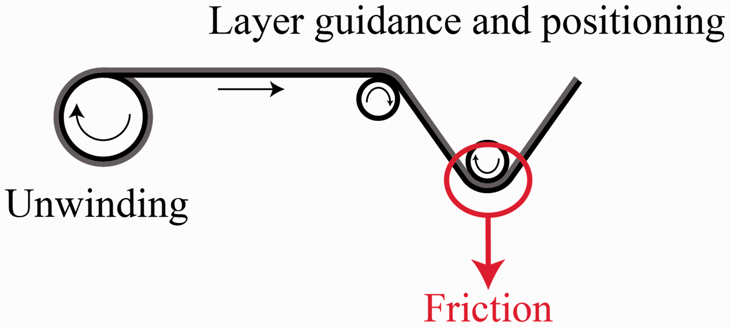
Materials and methods
CNTs grown on carbon surfaces
The CNTs grown on carbon fabrics used in this study were produced by NanoLab Inc. (USA). They are composed of ex-Polyacrylonitrile-based carbon fibres (7 µm in diameter) assembled into a nonwoven structure. The growth of multi-walled CNTs is performed on this surface using the in situ Chemical Vapor Deposition growth process, which allows the growth of CNTs on the whole surface of the carbon fibres [17]. Moreover, the growth of CNTs is realized with a temperature around 600℃ which means that the sizing of the carbon fibres is removed.
Figure 2 shows the aspects of the nonwoven reinforcement after the growth of the CNTs on the surface. It can be observed that the density of the reinforcement is small, but that the CNTs are grown homogeneously on the fabric and around the fibres. The length of the CNTs is approximately 2 µm, and they have a diameter of around 10 nm.
SEM pictures of the CNTs grown carbon fibre reinforcement: (a) general view, (b) with a magnification of × 50 and (c) with a magnification of × 3000.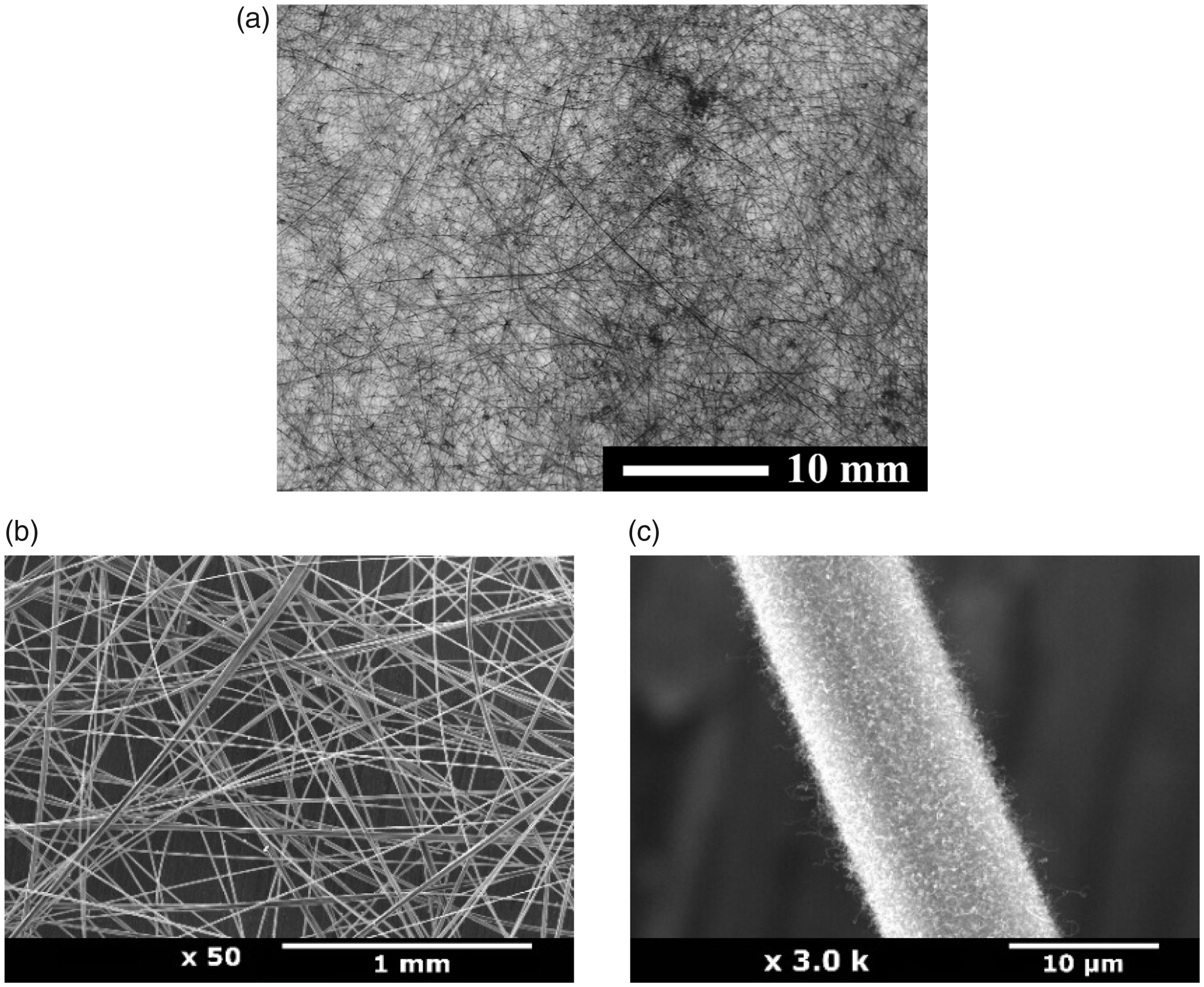
Experiment simulating the CNT wear
The wear of the CNTs was realized by compression with a press composite machine using a planar mould in order to ensure that the distribution of pressure on the fabric was homogeneous and polytetrafluoroethylene sheets to avoid sticking between the plies and the mould. The pressure is applied at one time on a pair of plies to create binding points between them (Figure 3(a)). The exerted pressure was chosen to induce wear of the CNTs and, in the same way, to limit the breaking damage of the fibres. Then, the value determined was around 10 MPa.
Manufacture of the composites materials: (a) compression of the plies and (b) final composite materials.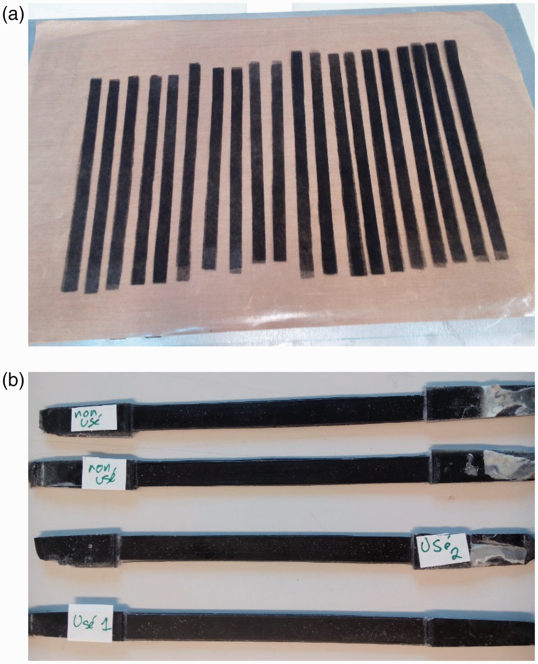
Manufacture of composite material
The composite materials are produced by contact moulding with EPOLAM 2020 epoxy resin from Axson Technology. The mould was covered with a release agent, and then the resin and the reinforcement were disposed successively, with the impregnation by hand between each ply of reinforcement. The number of plies in each composite piece corresponds to 20 plies. After hardening of the resin, the resin is cured by heating, with a temperature cycle of 1 h at 40℃, 1 h at 60℃, 1 h at 80℃ and finally 1 h at 100℃. The composite materials have a rectangular shape (width = 10 mm; length = 120 mm; thickness = 1.2 mm) with a reinforcement rate of 25%. Figure 3(b) presents the obtained composite materials, two with worn fabrics and two with unworn fabrics, however after the manufacturing of the composite materials.
Electrical measurement
The electrical properties of the composite materials were measured before and after wear of the CNTs. In fact, CNTs are naturally good conductive materials, and the goal is to study the influence of the orientation of the CNTs in the structure on the composites’ electrical properties.
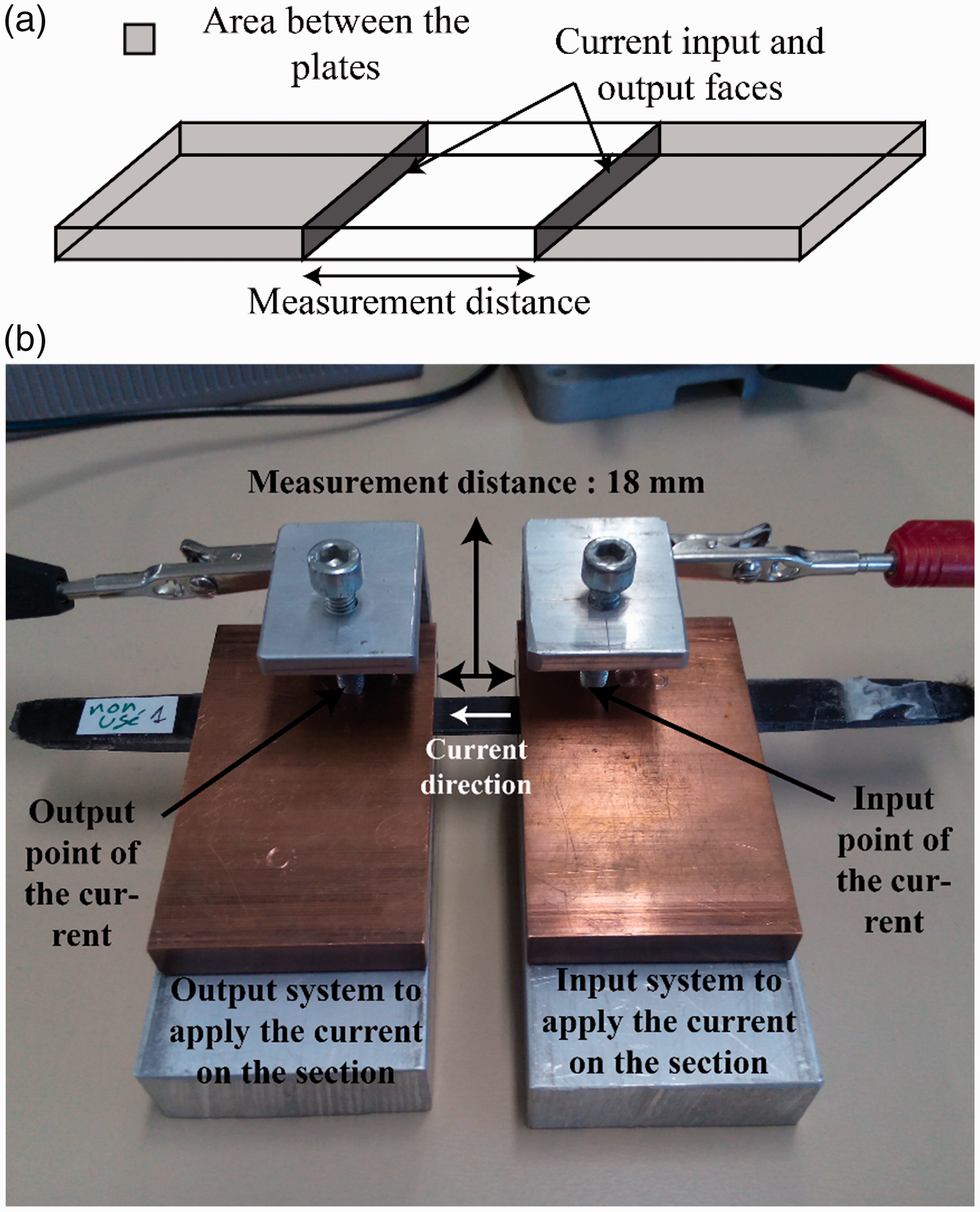
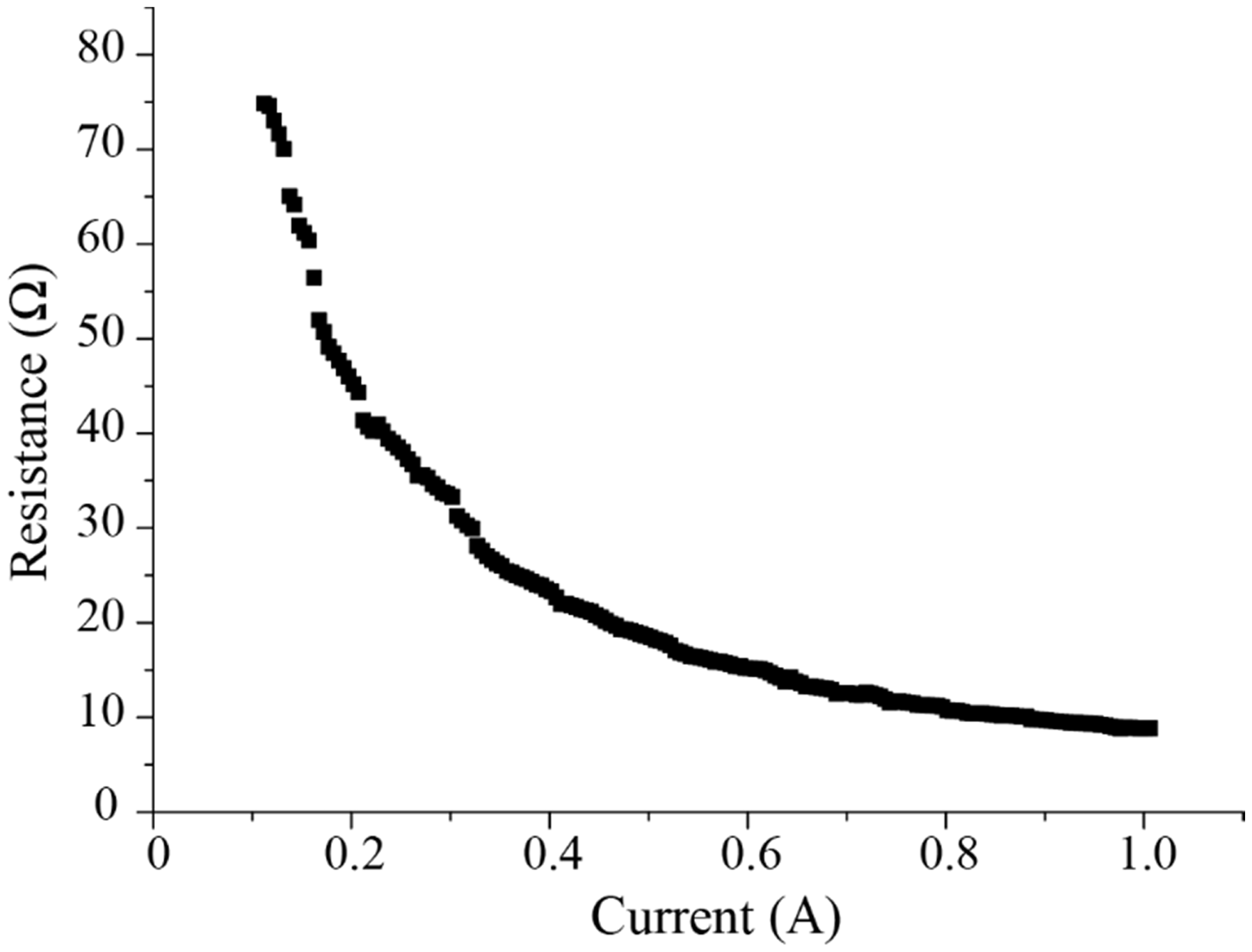
The measurements were done transversally (Figure 4) and longitudinally (Figure 5) and consisted of applying a electrical current supply to the materials (from 100 mA to 1 A) and measuring the tension between the two sides of the sample. These tests are realized in two different configurations relative to the kind of measurement: longitudinal (Figure 4) or transversal (Figure 5). The obtained curve is presented in Figure 6, which represents the evolution of the electrical resistance as a function of the applied current. To measure the electrical resistivity of the composite materials, the steady state is considered. It corresponds to the lowest resistance value (at higher current). For example, in Figure 6, the measured resistance is 8.8 Ω, leading to a resistivity of 3.87 Ω m. This value is then multiplied by the surface/distance ratio of the two sides of the sample (current input and output faces). This allows the electrical resistivity of the composite materials relative to the distance between the electrodes to be determined (in Ω·m).
Illustration of the technique used to determine the transversal electrical resistivity: (a) principle drawing and (b) picture of the system. The current is applied from the input to the output discs. Illustration of the technique used to determine the longitudinal electrical resistivity: (a) principle drawing and (b) picture of the system. The current goes leftward. Graph illustrating the electrical resistance as a function of the applied current, in that case a transversal measurement with an unworn fabric.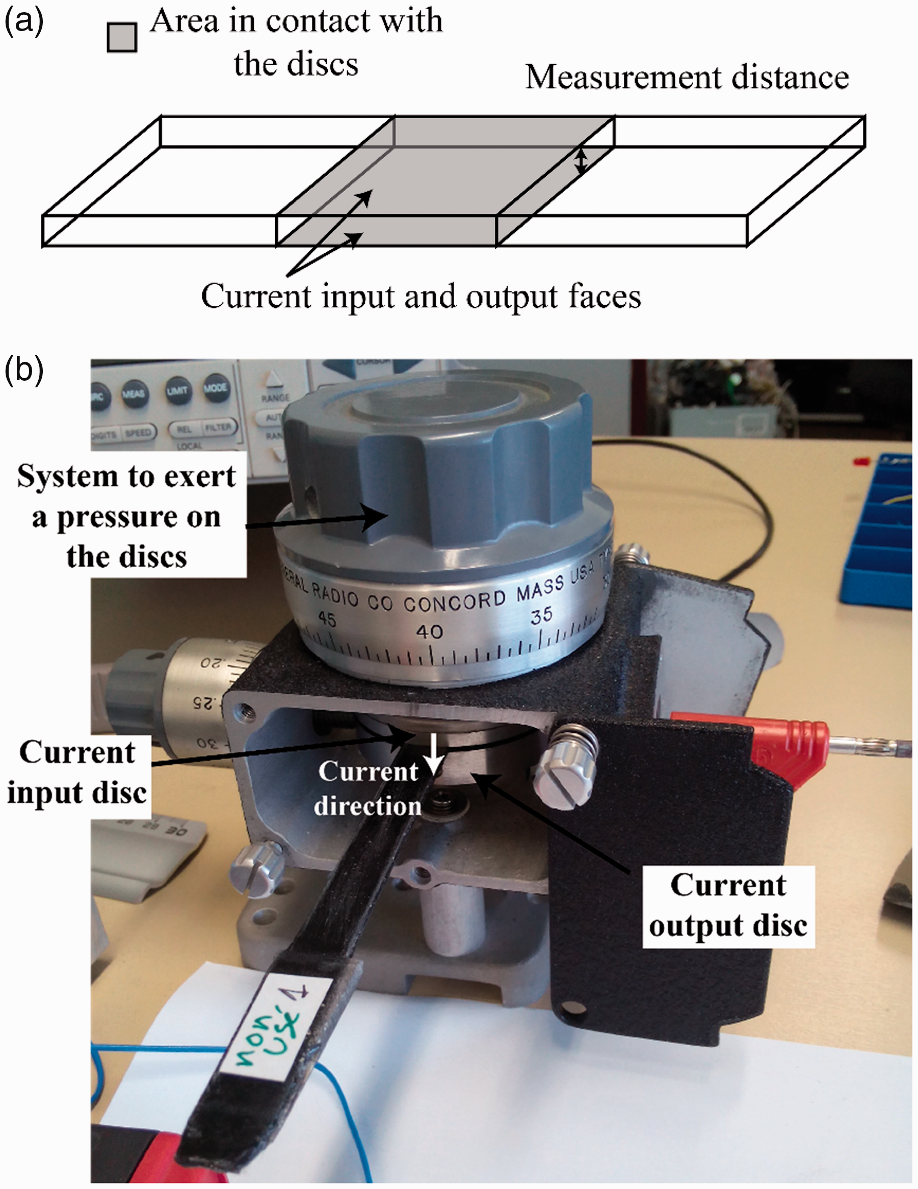
Mechanical measurement
The mechanical properties were measured by three-point flexural test in accordance with the NF EN ISO 14125 standard. Figure 7 presents the tensile machine (Figure 7(a)), and the three-point flexural system (Figure 7(b)) used to determine the mechanical properties. The length between the fixed supports is 20 mm (according to the standard, where distance/thickness = 16), and the force is applied in the middle of the sample until the breakage of the sample occurs. The tests were realized in an Instron 5985 tensile machine with a load cell of 2 kN (2580 Serie) with an accuracy with a maximum error of 0.15% of the load considered. The tests are displacement controlled and realized with a loading rate of 0.5 mm/min. During the test, the load and the displacement of the support are recorded, and then the flexural modulus, strain at failure and stress at failure can be calculated. Furthermore, the fracture surfaces were observed by scanning electron microscope (SEM).
Illustration of the method used to determine the mechanical properties of the composite material: (a) the tensile machine during a test and (b) the three-point flexural system.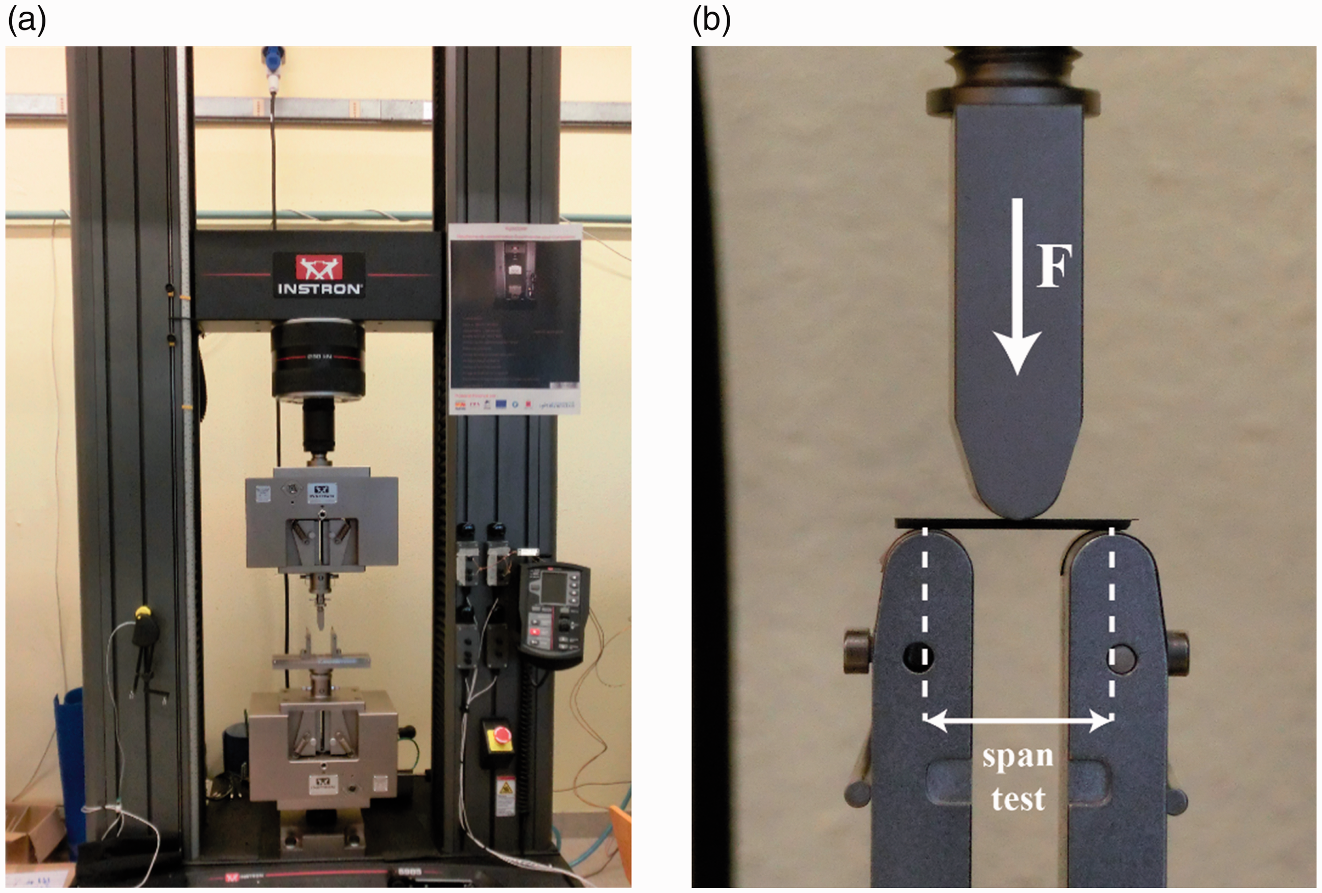
Results and discussion
Characterization and wear of the CNTs grown on carbon surfaces
The aim of the wear of the CNTs is to crush and align the CNTs on the surface of the fibres along their axes. However, as mentioned in a previous work, the structure of the CNTs is not modified by the wear of the surface [16]; they still have a cylindrical structure with no chemical or physical modification. Figure 8 shows the modification of the surface state of the CNTs grown on carbon fibres before and after the wear on the surface. Before wear, the CNTs were entangled around the fibre surfaces (Figure 8(a)). After wear, so after compression, they formed a transfer film on the surface of the fibres (Figure 8(b)), similar to the film observed after friction strain in previous studies [16].
SEM pictures of the CNTs grown on carbon fibres: (a) before wear, CNTs are entangled around the fibres and (b) after wear, CNTs are in the transfer film state.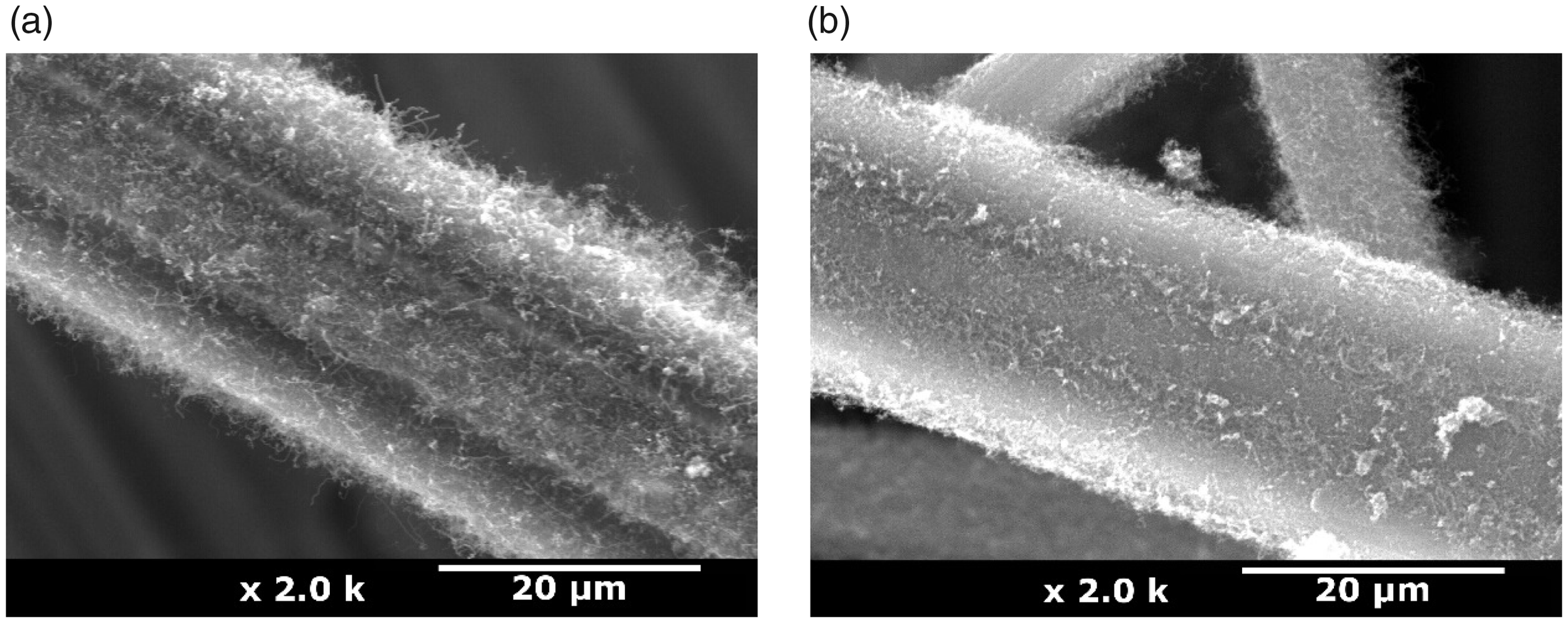
Two kinds of composite material pieces were produced: the first with CNTs entangled on the surface of the carbon fibres and the second with CNTs in the transfer film state, that is, before and after wear.
Electrical properties
Eight longitudinal measurements and 12 transversal measurements were made on each kind of composite material, that is, before and after wear.
Figure 9 shows the results for the electrical properties of the composite materials obtained by the longitudinal (Figure 9(a)) and transversal measurements (Figure 9(b)). The results presented are the composite resistivities in order to be independent of the distance between the electrodes used during the measurement.
Electrical resistivity of the composite materials before and after the wear of the CNTs: (a) longitudinal resistivity and (b) transversal resistivity.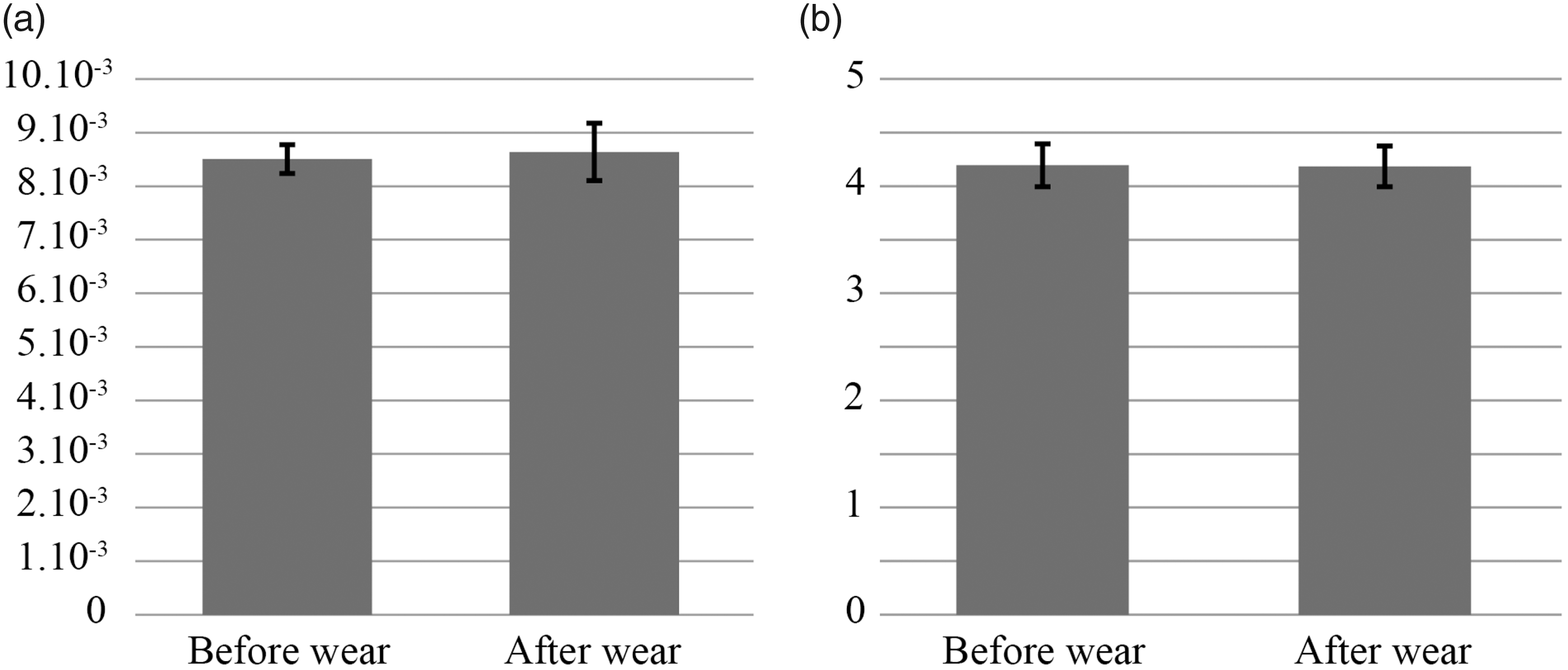
The resistivity of the composite materials is considerably higher in the transversal than in the longitudinal direction, which means that the conductivity of the materials is much higher in the longitudinal than in the transversal direction. This can be explained by the position of the CNTs in the structure and the nature of the reinforcement. In fact, the reinforcement has a nonwoven structure, which means that it is composed of 20 layers of CNTs grafted nonwoven structure, that is, plies overlaid on each other, that is, a multi-layered structure. Therefore, the conductivity is better on the surface layer than in the thickness of the multi-layered composite.
With regard to the influence of the wear of the surface, no significant modification of the electrical properties in terms of longitudinal or transversal resistivity can be observed. Therefore, it can be concluded that the orientation of the CNTs on the fibres (entangled or aligned with the fibres) has no influence on the electrical properties of the composites. As a reminder, the presence of the CNTs on the surface of reinforcement leads to a decrease in the electrical resistivity of 72% [8], and we have seen that the wear of the surface has no influence on the electrical properties of the composite material. Finally, it can be concluded that the growth of CNTs on the surface of reinforcement can be realized, without modification of the behaviour of the surface relative to the wear of the surface caused by the manipulation of the reinforcement.
Mechanical properties
Eight measurements were made for each kind of composite material, that is, before and after wear.
Mechanical testing of the properties of composite materials was done by three-point flexural tests. Figure 10 shows the stress–strain curve obtained for all the samples tested.
Flexural curve of three-point bending: (a) before the wear of the surface and (b) after the wear of the surface.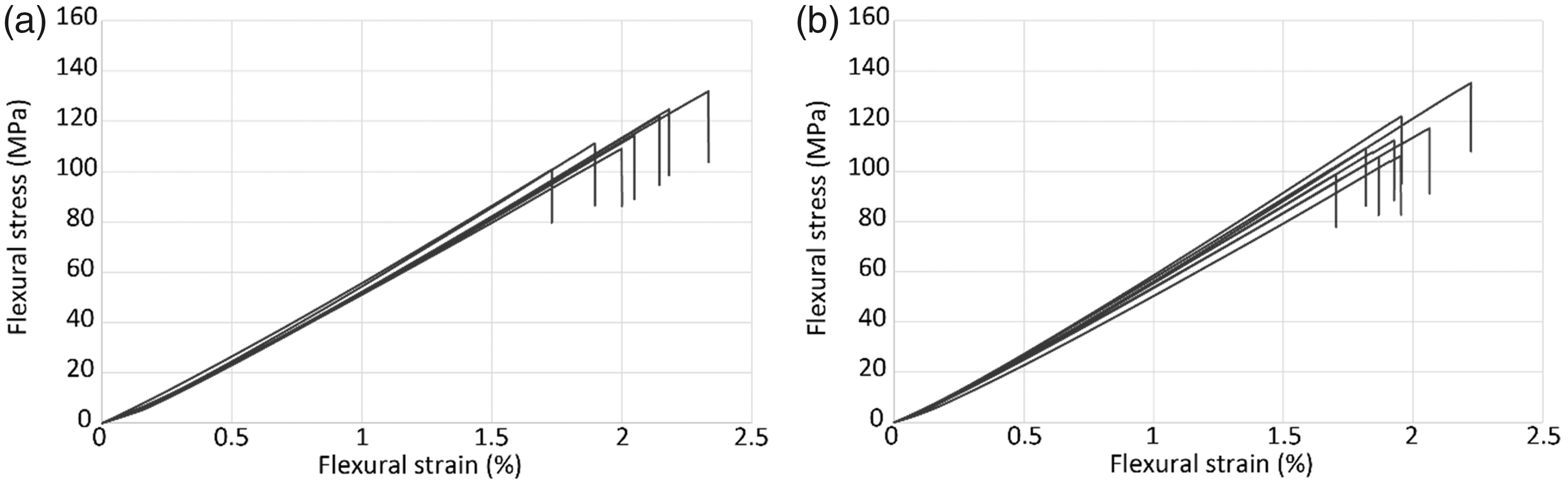
Figure 10(a) presents the curve for the surface before wear, and it can be observed that there is a small dispersion of the slopes of the curve, which represents the flexural modulus, but the dispersion is greater at the breaking point. With regard to the results after the wear of the surface illustrated in Figure 10(b), there is greater dispersion of the slope of the curve, that is, the flexural modulus, and the breaking point is highlighted.
From these curves, several parameters that are representative of the mechanical properties of the composite materials can be calculated. They are the flexural modulus (MPa) (Figure 11(a)) and, for the breaking characterization, the strain at failure (%) (Figure 11(b)) and stress at failure (MPa) (Figure 11(c)).
Mechanical properties in three-point flexural tests of the composite materials as a function of the state of the surface: (a) flexural modulus, (b) strain at failure and (c) stress at failure.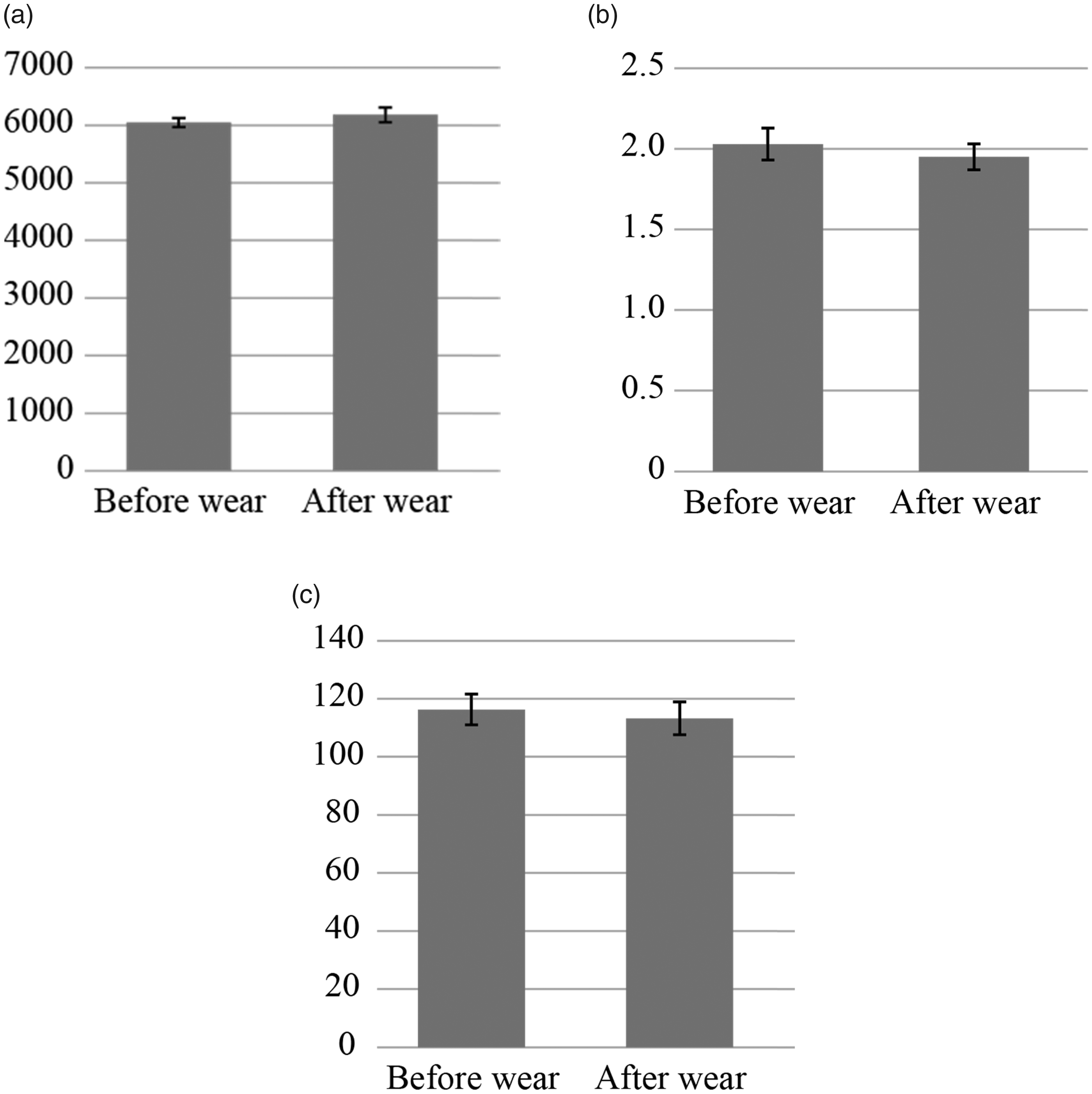
From these results, it can be concluded that there is no significant difference between the two states of the surface, that is, before and after wear, in terms of the strain at failure, stress at failure and modulus. Concretely, this means that the wear of the surface has no significant influence on the mechanical properties of the composite material investigated.
Furthermore, the characteristics of the failure were observed by SEM in order to detect the failure mode. Figure 12 presents the fracture surfaces, and it can be observed that the failure is brittle, with the breaking of several fibres, which are pulled out of the matrix (Figure 12(a)). Magnification on the pulled out fibres (Figure 12(b) and (c)) reveals that there is no more trace of matrix on the fibre surface, which means that the failure appears between the fibre and the CNTs. It is also possible to see the crack due to the fibres in the matrix (Figure 12(d)).
SEM observation of the failure mode of composite materials: (a) general view, (b, c) magnified view of pull-out fibres and (d) magnified view of crack due to pulled out fibres.
As a reminder, the presence of the CNTs on the surface of reinforcement leads to an increase in the mechanical properties, for example, an increase of 16% for the flexural modulus [8]. It can be concluded with regard to the mechanical properties that the wear of the surface caused by the manipulation of the reinforcement does not change the mechanical properties of the composites (modification lower than ± 2%), and the weak point has been identified to be between the fibres and the CNTs.
Conclusion
From some results mentioned in the ‘Introduction’ section, the presence of CNTs on reinforcement fabrics has the properties to enhance the electrical and mechanical properties of composites materials. However, these results were obtained without industrial handling of the reinforcement, which can modify the CNTs on the fabric. In this paper, the influence of the reinforcement handling, with the winding, unwinding and guidance of the fabric on roll, on the properties of composites materials is studied. Indeed, previous studies have shown that the reinforcement handling causes modification on the CNTs, as the formation of a transfer film on the surface of the fabric. This film is composed of CNTs without structural modification. However, this modification of the surface state of the reinforcement can have an influence on the electrical and mechanical properties of composites materials. For this, some composite materials with CNTs before and after wear of the surface were manufactured, and the results clearly show that the state of the surface (i.e. the state of the CNTs) has no influence on the electrical and mechanical properties of the composite materials. This means that the manufacturing of the composite materials with CNTs grafted reinforcement can be industrialized with no modification of the final properties, even after reinforcement handling, winding and unwinding.
Footnotes
Acknowledgements
The authors would like to express their gratitude to Dr Gildas L’hostis and Dr Jean-Charles Peruchetti, associate professors at the University of Haute Alsace, for their help and advice regarding the mechanical and electrical measurements, respectively.
Declaration of conflicting interests
The author(s) declared no potential conflicts of interest with respect to the research, authorship, and/or publication of this article.
Funding
The author(s) received no financial support for the research, authorship, and/or publication of this article.