
Abstract
Non-crimp fabrics are fabric tapes stitched to an adjacent orthogonal fabric with no associated crimp. In the current research, the effect of fixation polyester stitches in improving through-the-thickness properties of non-crimp fabric composite laminates is investigated. Detailed experimental studies on interlaminar fracture toughness and static indentation properties of stitched and unstitched thin ply carbon fibre epoxy composites have been conducted. About 23% higher peak load and 37% higher energy absorption were noticed during static indentation tests for the stitched ply composites. A detailed SEM investigation has shown that the stitch-stitch interaction
Introduction
Composites are overtaking all materials where weight is primary design variable. Composites acquire properties like high strength/weight and stiffness/weight ratio, high fatigue, corrosion resistance and also greater stability in thermal environment [1–3]. But the excessive usage of composite brings more challenges as the failure modes and damage mechanism associated with composites are much more complicated. Damage mechanism is a function of the type of reinforcement and matrix system used, laminate stacking sequences and also the kind of loading [4]. Typical damage modes associated with composites are microcracking in through-the-thickness direction (transverse microcracking), followed by delamination and fibre breaking [5]. Even, there is the likelihood of catastrophic failure without fibre breakage [4]. Non-crimp fabrics (NCFs) are the class of textile fabrics where low thickness tapes are stitched to an adjacent orthogonal fabric with no associated crimp [4,6–15]. Taking into consideration the failure modes of the composites and focusing on suppressing them, a new technology so-called “spread tow thin-ply technology” is developed where dry ply of weight less than 100 g/m2 is achievable. In the process, flat tapes of low thicknesses are produced by mechanically spreading the larger tows like 12 K, 24 K, etc. [4]. Stitches used as binding yarn or fixing or positioning in NCFs are polyester (PES) yarns which can be thin with high elongation or thick with less elongation and are termed modified lock and chain stitch, respectively [16]. The process is not only cost-effective to bring through-the-thickness reinforcement in 2D fabrics, but it also eases handling the dry fabric preform. Also, the processing of these fabrics is possible with cost-effective liquid injection processes like Resin transfer moulding (RTM) process and vacuum-assisted RTM process [17].
Depending on the loading scenarios, stitching can dramatically improve or degrade the overall performance of the composite [17]. There is considerable literature available on the effect of structural stitching in enhancing the out-of-the plane response of the composite system mostly reflecting on Mode I and Mode II fracture toughness as well as impact and compression after impact performance [17–26]. Also, the effect of stitch types, stitch density and stitch pitch in view of structural stitching has been carried out by many researchers [19–22,24,26–28]. The majority agrees with lower in-plane performance due to structural stitching, while there is agreement over the improved out-of-the plane performance of composites [5,19–22,24,26–28]. While the tensile strength due to structural stitching is found to be 20% higher [29], the contradicting results showed approximately 45% reduction in the tensile strength. The compression after impact response of stitched composites was found to be 80% higher [30], while the Mode I fracture toughness was increased by 1460% compared to un-stitched composites [20]. There is literature available on the effect of fixation stitches in NCFs to improve the in-plane performance of the composite, where the tensile, short-beam and in-plane shear performance of non-crimp fabric composite were investigated [31]. But few studies are available which highlights the significance of holding yarn stitches in improving the out-of-the plane performance of non-crimp fabric composite system. It is apparent that improvement which NCFs alone bring as compared to structurally stitched NCFs is lesser, but it should be noted that the high tension stitches and even fibres used tend to compromise significantly with the in-plane properties of the composites [32–34]. Still, the NSFs with fixation stitches are competitive solutions to woven, knitted [35] and other class of textile composites considering the processing, handling as well as the advantage it offers regarding mechanical performance. This research aims to investigate the static indentation (SI) and Mode I fracture toughness of thin ply PES-stitched non-crimp carbon fabrics, and the baseline comparison study has been carried out with the counterpart unstitched variant. The details of the experiments conducted and the deduction of failure mechanism through microscopic and scanning electron microscopic (SEM) were carried out to find the underlying reasons for the improvement offered by fixation stitched non- crimp fabrics.
Materials and experimental details
Materials
The reinforcement used in current research consisted of stitched or unstitched ( ± 45°) bi-angle 75/75 g/m2/ply fibre areal weight NCF C-Ply™, (0°/+45°) 100/100 g/m2/ply fibre areal weight NCF C-Ply™ and (0°/−45°) 100/100 fibre areal weight g/m2/ply NCF C-Ply™ from CHOMARAT. The bi-angle C-Plies were stitched with PES yarn with a linear density of 35 dtex. The stitching pattern used was chain tricot for (0/−45 and 0/45) plies, while the chainete stitch was used for (+45/−45) bi-angle ply. The epoxy matrix used for all the composite system manufactured was Epolam 5015/5015 resin from AXSON. This resin tends to cure at room temperature using liquid injection processes followed by 2 h of post curing to achieve optimal mechanical performance.
Laminate manufacturing
Stitched and unstitched preforms were stacked following (a) Bi-angle (0°/−45°) C-Ply™ (b) (b) Bi-angle 

The entire RTM manufacturing process included the steps where the preform was first placed on the bottom half of the mould, followed by placing the frame and closing the mould. After closing the mould, the resin was injected at 2 bar pressure. The injection was continued till the resin reached the outlet completely without any bubbles which usually signals the race tracking. After the injection, the laminate was cured for 18 h at room temperature followed by 2 h of post curing at 60℃, and finally the laminate was demoulded.
Panel quality assessment
The quality assessment for the manufactured composite laminates was carried out in terms of the porosity or the void content. A quantitative estimate of void content was carried out using ASTM D792 and ASTM D2734-09. ASTM D792 method was used to calculate the composite measured density, while ASTM D2734-09 was used to calculate composite theoretical density and void content. Panels with void content <1.5% were used for mechanical testing.
Mechanical testing
Manufactured composite laminates for respective SI and double cantilever beam (DCB) tests were cut to dimensions according to their respective ASTM D6264 and ASTM D5528-13 using a water jet cutting machine.
SI test

Details of specimen dimension and configuration for DCB and SI tests.
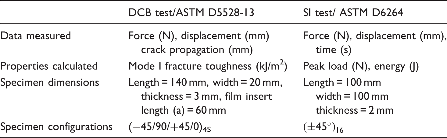
DCB: double cantilever beam; SI: static indentation.
DCB test
ASTM D 5528-13 standard was used for Mode I fracture toughness test. Specimens were labelled and measured before conducting the tests. A thin PTFE film of around 20 microns was put at the midsection of the laminate to initiate an artificial delamination or crack. The Teflon insert was placed 60 mm length inside the laminate and the width of the insert was same as that of the laminate. Two blocks with centre holes were glued to the specimens with strong Araldite resin. Laminates were painted in white with typewriter correction fluid on the side and were marked in each millimetre to facilitate the view of the crack growth. The standard used for DCB test, specimen dimensions and the laminate configurations tested are presented in Table 1. The specimen was peeled in pure Mode I by pulling the two metal blocks. A digital camera (Canon EOS 70D with 7 fps continuous shooting capability) was filming the side of the specimen to facilitate the view of the propagation. The Mode I inter-laminar fracture energy is given by equation (3).

Microscopic investigation
SI specimens for microscopy
The first step in preparing the specimens for microscopic investigation was sectioning. The section of interest was selected according to the extent of observable surface damage. It was cut and grinded into the size of 25 mm × 25 mm for fitting into the mould. The cut section was deburred at the edges using sandpaper to remove unintended surfaces. The sectioned part of the composite sample was embedded in a mould which was filled with resin. Grinding step was carried out such that stitches in stitched specimens were observable under microscope or SEM. The stitched specimen was grinded to the depth just before reaching the stitch of outermost ply layer to clearly observe the stitches between the first and second layer of fabric and possibly from other layers as well. After the grinding, specimens were polished using a diamond lubricant such that the final laminate was scratch and deformation-free. The above steps provided a cleaner view to examine the cross section of the indented laminate.
DCB specimens for SEM
The specimens were coated with a thin layer of gold via sputter coating, for scanning electron microscope (SEM) observations. The JEOL Auto Fine Coater JFC-1600 was used for this purpose along with JEOL JSM 5600 SEM for fractographic investigation of the failure surfaces (25 mm ×25 mm) to understand the difference in the failure modes of various composite specimens.
Results and discussions
SI test
Load–time curve (refer to Figure 2(a)) for both stitched and unstitched carbon composites samples was analyzed. Five specimens were tested for each group of laminate configuration, and the graph which is the best representative of the average value is shown in Figure 2.Test results showed that the presence of PES fixation stitches improved the load bearing performance of the composite system. The presence of zig-zags in the load-time curve for stitched sample indicates the resistance provided by fixation stitches, while the curve for unstitched samples was comparatively smoother than the stitched sample. Also, from the energy–time curve (refer to Figure 2(b)), the amount of failure energy for the stitched sample was found to be significantly higher than the unstitched sample and also indicates the delay in the failure within the composites samples. There was 23.6% higher peak load and 37.9% higher failure energy noticed for PES-stitched composites compared to unstitched variants (refer Figure 2) before the catastrophic failure of the composite system.
(a) Load–time curve for composite laminates in SI testing and the peak load for failure (b) Energy–time curve for composite laminates in SI testing and the failure energy.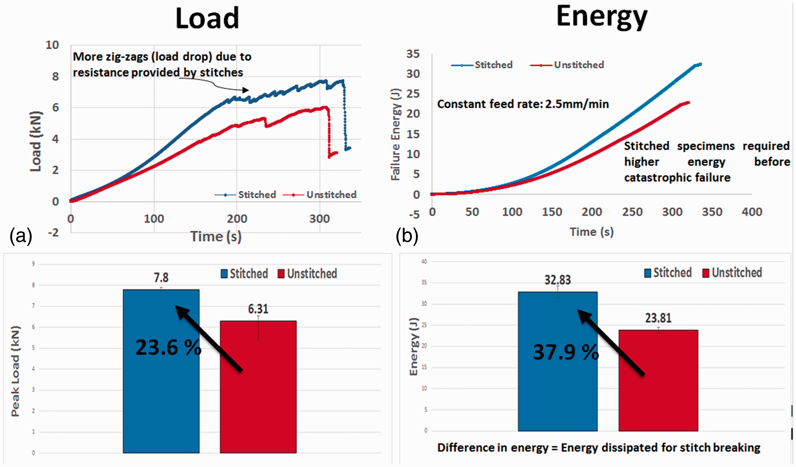
As can be seen from Figure 3, much larger delamination was observed in case of unstitched composite compared to the stitched composite system. While the fibre breakage, crushing and rupture were regular features in both the composite systems, clearly the lesser extent of damage is attributed to the presence of thermoplastic PES stitches.
Micrographs of failed composite laminates after SI testing (a) stitched laminate (b) unstitched laminate.
The detailed microscopic investigation has been carried out to deduce the failure mechanism. Stitch pattern in Schematic of stitching pattern for 
Microscopic studies using an optical microscope and scanning electron microscope were carried out to investigate the microstructure of stitches and fibres in indented samples. Microscopic images as seen from Figure 5 showed that the stitches play a part in holding the bi-angle plies in an event of out-of-plane loading, which resulted in reduced intra-ply fibre distortion and inter-ply delamination. As can be seen from Figure 8, two failure mechanisms were deduced which helps in reducing the delamination extent and make the stitched composite comparatively more impact resistant and also absorbing more energy thanks to the PES stitches. Figure 5(a) shows that the stitches within the bi-angle ply help to reduce the delamination, while Figure 5(b) shows how the stitches between two bi-angle plies also bridge the delamination extent.
Deduction of failure mechanism in reducing delamination extent (a) stitches within bi-angle ply (b) stitches between the bi-angle plies.
Schematic, as shown in Figure 6, shows the detailed stitch failure mechanism within the bi-angle ply. Figure 6(a) shows the laminate state prior to indentation with high-stress concentration at the intersection of the two stitches in the (a) Detailed stitching failure mechanism within the bi-angle ply (a) prior indentation (b) after indentation.
Figure 7 shows the detailed stitching failure mechanism between two bi-angle plies. As can be seen from Figure 7(a), usually there can be two possibilities of the stitch alignment between the two adjacent plies. Perfect positioning of two bi-angle plies during the preforming is not possible. It can either be fully aligned at few locations while there is also a possibility of non-alignment in certain locations as can be seen from the enlarged side view. Figure 7(b) shows the broken stitches between two bi angle Detailed stitching failure mechanisms between two bi-angle plies. SEM micrograph showing PE stitches bridging the delamination extent. SEM: scanning electron microscopic.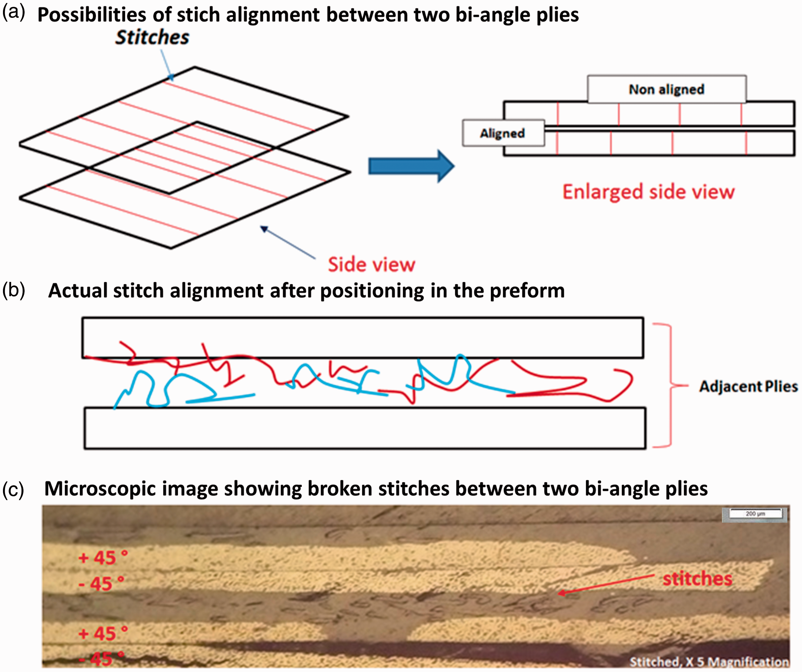

DCB test
DCB tests have been carried out on various laminate configurations as shown in Table 1. Stitched and unstitched composite laminates were tested to investigate the effect of stitching in resisting the crack growth. It should be noted that the layup considered for the testing was chosen to accustom the ASTM D5528-13 standard and the two unidirectional plies are separating the delamination plane. Load–displacement curves for both laminate configurations are depicted in Figure 9(a). As can be seen in Figure 9(a), the peak loads to break for stitched composited composites were constantly higher compared to unstitched C-Ply™ epoxy composites. The more prominent load drop points for stitched composite laminates correspond to stitch breaking or pulled out, while also the increased displacements between the load drop indicated the higher crack resistance due to extra toughening provided by the PES stitches in through-the-thickness direction.
Experimental DCB results for composite laminates (a) Load–extension curve (b) Crack resistance, R-curve (c) critical energy release rate for laminates. DCB: double cantilever beam
R curves (Figure 9(b)) show much higher initiation as well as the critical fracture toughness energy values for stitched composite compared to unstitched composite. The crack propagation as seen from Figure 9(b) for the unstitched epoxy composite system was found to be very stable, while the crack propagation in case of the unstitched composite was found to be the one with inconsistent delamination, especially in the earlier stages due to more evident load drops as seen from the load–displacement curve. Figure 9(c) depicts the Mode I fracture toughness values for composite systems and the coefficient of variation from the average values of the five specimens are indicated using the error bars. There was 26.5% higher critical energy release rate noticed for stitched composite compared to the unstitched variant. The surface morphological study was carried out on tested stitched and unstitched specimens. As seen from Figure 10(a), massive fibre bridging was observed near the stitching sites. Along with fibre rupture and splitting, fibre bridging enhances the fracture toughness by resisting the crack growth. The less severe fibre bridging and splitting were also the feature of the unstitched laminate (refer to Figure 10(c)) which is a normal feature seen in multi-directional composite [36,37]. Although intralaminar fracture toughness was the dominant feature in case of structurally stitched composites [38], in current research it is deduced that fixation stitches are playing a prominent role in increasing the delamination within the layer which is a toughness enhancing mechanism. Figure 10(c) interestingly shows the formation of cusps near the pulled out stitches which are usually the Mode II delamination failure mechanism, which is caused here by stitch debonding from the epoxy matrix. These cusps formed here are due to through-the-thickness constraint provided by the PES stitches.
SEM images of surface morphology specimens after DCB test (a) stitched laminate showing stitching with massive fibre bridging (b) stitched laminate showing formation of cusp (c) unstitched laminate showing fibre splitting with limited fibre bridging. DCB: double cantilever beam; SEM: scanning electron microscopic.
Conclusions
In current work, the detailed experiential and microscopical analysis was carried out on thin non-crimp fabric composites with PES fixation stitches and its out-of-plane performance was investigated and compared to that of unstitched non-crimp fabric composite. Following are the salient finding of the research
(1) Stitched NCF composites were found to have 24% higher peak load and 38% higher failure energy undergoing SI test compared to unstitched composite. (2) It is deduced that PES stitches “between” and “within” the bi-angle non-crimp fabric ply significantly reduce the delamination by absorbing more energy. It was noticed that these stitches suppress the delamination caused as a result of excessive fibre distortion due to shear and bending caused by out-of-the plane loading. (3) The Mode I performance of PES stitched composite was around 26% higher in terms of critical energy release rate. Enhanced fibre bridging was noticed in case of stitched composites and these stitches are found to increase the delamination resistance within the ply which is a toughness enhancing phenomenon.
Footnotes
Declaration of conflicting interests
The author(s) declared no potential conflicts of interest with respect to the research, authorship, and/or publication of this article.
Funding
The author(s) disclosed receipt of the following financial support for the research, authorship, and/or publication of this article: The authors would like to acknowledge the financial support from Institute for Sports Research, Nanyang Technological University, Singapore and CHOMARAT, France and ARKEMA, France.