
Abstract
Joining textile layers to a preform using patches is of utter importance in regards to producing structural elements made of fibre-reinforced materials with complex geometry, and repairing fibre-reinforced composites in an efficient and safe manner. Material-efficient and load-specific design and integration of the patch are essential in relation to the performance of the joint as well as the strengthening of the composite structure after a damaging event. Hence, in this study, the stress–strain behaviour of carbon-fibre-reinforced epoxy-composites, which are joined by a patch designed as double-lap joint, will be investigated. It will be shown that the woven fabric morphology (surface structure) and the woven fabric construction (weave pattern) of the join partners exert a noticeable influence on the stability of the patched composite samples. The use of leno non-crimp fabrics as patch structures, which provide an increased joint surface in comparison to the likewise examined twill fabrics, enables a growth in joint strength, provided that the dimensions of the patch remain the same.
Introduction and problem definition
The application of textile-reinforced semi-finished products in a material- and cost-efficient way is a significant factor to produce economical fibre-reinforced composites. In terms of woven fabrics or multiaxial fabrics, they are used for large-scale production in the automotive and aviation industries and also for small-scale production such as wind power as well as mechanical and plant engineering. Last but not least, they are enjoying growing popularity in the manufacturing of sporting goods [1,2].
Textile semi-finished products can be processed in various forms, depending on the application and the used type of fibre-matrix-pairing. There are dry textile semi-finished parts that are processed to preforms by either completing a single-step procedure (direct preforming, for example with integrally produced 3D-woven fabrics) or a multistage procedure (sequential preforming) [3]. Subsequently, the preforms are impregnated and consolidated with a duroplastic resin system. Another possibility is to attach the matrix material to the textile semi-finished products even before processing and thereby manufacturing them in combination with a duroplastic resin system or rather a thermoplastic matrix (Prepreg) [4,5].
Preforming is a significant sub-process to manufacture fibre-reinforced composites, which consists of building the preform in layers in accordance with the geometry of the component. This includes, amongst others, cutting, draping and – in case several tailored semi-finished products are necessary to display a single layer of the reinforced composite component – connecting the provided semi-finished products with one another. The cutting of the semi-finished products is required to adjust the textile layers to the contour of the preform. Also, cutting textile layers into pieces to realise complex component geometry helps to avoid wrinkling and structural distortion. Following this, the customised layers of reinforced fabrics are sewed or fixed using binders [6]. It should be ensured that the joint area between the layers are of the proper size and fit according to the requirements of the application. Because there are no reinforcing fibres connecting the reinforcing plies or in case the plies are joined by sewing, just little reinforcing fibres connect the draped plies. In the joining zone, the stresses affecting the building components are mainly transferred interlaminarily by the matrix [7].
The overlapping area needs to be designed according to the anticipated loading, which is also of importance in regards to repairing the damaged fibre-reinforced composites by applying a patch. Here, the matrix material is removed locally from the damaged area and the components' damaged area is strengthened by applying repair patches made of equivalent textile reinforcing material. In the work of Küchler et al., a procedure is presented, which allows a local degradation of a thermoset matrix of a damage composite part in order to apply a patch [8]. The proposed method is based on thermal activation by infrared radiation of oxide semiconductors. Afterwards, new matrix resin is applied and cured and the fibre-reinforced composite component is restored [9–11]. Overlap areas and patch structures cause due to the joining process an increase of the structural weight of the components and also represent potential mechanical weak spots. Therefore, the size of the required overlap area is substantially determined by the anticipated loading cases, the resulting stresses within the joint as well as the connection quality between the patch and the basic structure. Reducing the stresses affecting the joint area, which occurs due to a high loading case, can be achieved by an enlarged joint surface. The expansion of the overlapping area by expanding the patch only results in a distinctly slow rise in the joint' fracture load, whereas the structural weight increases and the material efficiency decreases [12].
Another possibility to enlarge the effective joint area is to modify the joining partners' surface using textile semi-finished products with a suitable surface structure. In the study of Zeng and Sun [13], a single-lap joint is presented. Here, the applied woven fabrics are wave-like converted, then stacked while overlapping and finally consolidated by autoclave. The study has shown that the wave-like joint is characterised by a doubled joint strength in comparison to the reference single-lap joint. This can be explained by the homogenisation of shear and peeling stresses of the joint across its entire surface. However, this procedure requires deformation of the textile layers, which have to be joined together. Therefore, it is hardly suitable to repair composite components.
However, joining textile layers in order to repair a damaged composite structure or to connect textile layers of a preform is mainly based on adhesive bond. A joining method which combines a high portion of form closure besides an adhesive bond without a deformation of the textile joint partners is not state-of-the-art so far. So, the focus of this article is to investigate the influence of the morphology of woven semi-finished products on the failure behaviour of joints consisting of patch layers in a carbon-fibre-reinforced-composite with epoxy matrix. For this purpose, two different types of fabric will be used as patch layers in order to join two layers of a basic structure in the form of a double-lap joint. The fabrics used as patch layers will be conventional twill weave on the one hand and a new type of leno weave on the other hand. Compared to the use of pure twill patch layers, it will be demonstrated that the use of patches made of leno fabric leads to an improved load bearing capacity of the joined composite structure.
Materials and methods
Types of semi-finished products used
Structural parameters of manufactured fabric types.

The woven fabrics are manufactured on a weaving machine type Dornier P1 with an integrated open-reed-weaving-module. This machine is equipped with a reed opened to the top as well as a special heald frame including laterally, in weft direction adjustable needle bars, in order to integrate additional warp yarns appropriately into the woven fabric [14]. The expansion of the woven fabric to an additional yarn system provides the possibility to produce leno fabrics by connecting warp and weft yarns by means of an additional warp yarn system (leno yarn system). Processing the warp yarn and leno yarn systems of two separate warp let-offs results in a woven fabric characterised by a non-crimp warp and weft yarn system as well as a leno yarn system entwining the intersecting points of warp and weft yarns. Upper and bottom side of the applied leno fabric according to Table 1 and a geometrical model of the leno fabric are presented in Figures 1 and 2.
Top surface of leno fabric (left: original structure; right: geometrical model). Bottom surface of leno fabric (left: original structure; right: geometrical model).

The processed leno and twill fabric exhibit differences in morphology due to the type of weave. While the twill fabric is characterised by a flat top and bottom surface, the characteristics of the examined leno fabric differentiate in regards to their top and bottom surface, in spite of equal warp and weft density (see Figures 1 and 2). The leno yarns' helical progress results in a strong bundling – especially in the case of warp yarns – and thereby evolves into a wavy bottom surface, which is characteristic for this type of leno fabric (see Figure 2).
Sample production and investigation
Samples sizes.
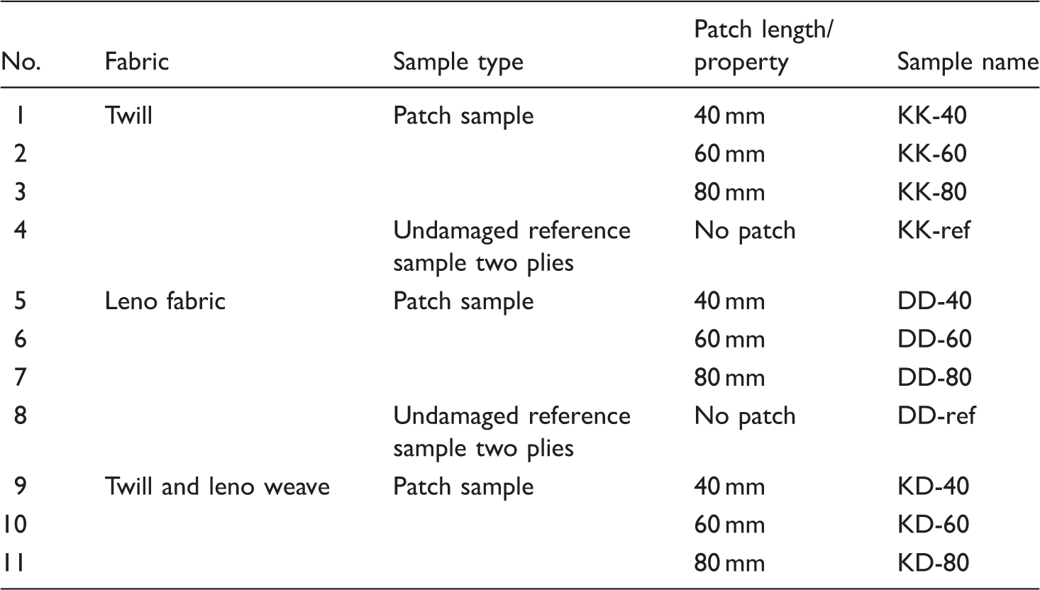
The reinforcing fabrics conventionally used for the production of fibre-reinforced materials are composed of perpendicular crossing and crimped yarn layers, whereby weft and warp yarns can be detected alternating on the woven fabrics' top and bottom side. This alternation takes place in plain and even-sided twill weaves (for example twill 2/2) on both woven fabric sides equally, wherefore the differentiation regarding the structure of the preform as well as coding of the laminate structure is not required in general [17].
In the case of the examined leno fabric, it should be noted that the warp and weft yarn systems are not supposed to crimp. That means the warp and weft yarns remain within their particular fabric side. With regard to the preform structure, the leno fabric can be displayed by two fibre layers in either (0°/90°) or (90°/0°) configuration (see Figures 1 and 2). In order to manufacture symmetrically structured fibre-reinforced composites, the fabric layers in conventional plain or even-sided twill weave has to be stacked only with equal fibre orientation. When using a leno fabric, the single layers need to be stacked by monitoring the position of the bottom and top side to create a symmetrically composite. For this reason, two layers of leno fabrics could be stacked in (90°/0°/0°/90°) and (0°/90°/90°/0°) configuration to create a symmetrical layer structure.
In total, each patch samples' preform consists of four layers. The reference undamaged test samples consists therefore of two reinforcing layers. Regarding the samples exclusively made of twill fabric (KK), it is sufficient to stack the layers with the same angle. In contrast, regarding samples made solely of leno fabric (DD) as well as samples consisting of a combination of leno and twill fabric (KD), the proper orientation of the layers' top and bottom sides needs to be assured as well.
To develop the preform, tailored woven fibre layers are stacked in the form of double-lap joint. This type of joint is commonly applied when testing the joints of fibre-reinforced composites [18–21]. Thus, due to the symmetrical layer structure of the sample, no additional bending moments are inserted into the samples. The use of douple-lap joints also enables a uniform stress distribution throughout the joint zone. This would not be possible in the case of a preform structure with a single-lap joint [22]. Considering the just described approach, the following layer structures of the samples are applied (coding according to [17] is applied).
twill/twill (KK): ((0/90)K/(0/90)K)S leno/leno (DD): (90/0/0/90)S leno/twill (KD): (90/0/(0/90)K)S
The design of the layer structure for the leno/leno samples is displayed in Figure 3(a) and (b), the one for samples made of leno and twill fabric is displayed in Figure 3(c).
Stacking sequences while preforming (a,b) leno-leno and (c) leno-twill.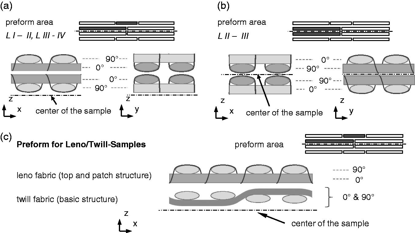
The production of the samples takes place in Vacuum-Assisted Resin Infusion Moulding (VARI). The semi-finished layers required for the preform structures are tailored and stacked according to the conditions of the test set up (see Figure 4).
Structure of the preform and performance of the samples.
The reinforcing plies L II and L III correspond to the basic structure in the centre of the sample, whose fibre reinforcement is interrupted. This interruption can occur due to either the sequential preforming process or a damaging event. The external layers L I and L IV consist of a patch to bridge the interruption of the basic structure and an additional top layer. The covering layers are composed of the same material as the patches. These prevent the preform from deformation while undergoing consolidation and serve as load input elements during testing. Finally, the VARI-development is completed by means of vacuum foil (see Figure 5). Epoxy resin type EPIKOTE ® RIM 135 in combination with the hardener RIMH 137 is used as a matrix system.
Infiltration structure for the production of test plates. (a) complete VARI-set-up; (b) detail of the VARI-set-up without cover panel; (c) detail of the VARI-set-up with cover panel.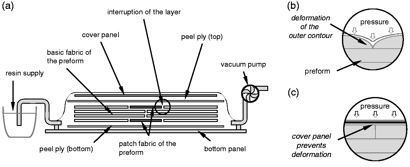
As preliminary tests regarding the sample consolidation have shown, the vacuum foil penetrates the preform on the top surface along the cutting edges as a result of evacuation (see Figure 5(b)). The dents caused by this are then transferred onto the sample plate, which affects the mechanical properties and thereby the test result. Thus, a flat cover plate is added to the infiltration structure; more precisely, it is placed between the preform and the vacuum foil, so the preforms' form stability can be assured during consolidation (see Figure 3(c)). Moreover, the preforms' top and bottom side are provided with layers made of peel ply that is removed after the demoulding process. In this way, the samples obtain a distinctly rough surface so that post treatment becomes redundant.
The determination of the test samples is achieved by means of a tensile shear test performed with the universal tension test machine Z100 (Zwick GmbH & Co. KG, Germany). The test, as well as the sample preparation, is based on DIN EN ISO 527-4 for determining the tensional behaviour of reinforced materials and the requirements for sample type 3 with additional load inputs elements [15]. In regards to sample preparation, neither sanding nor glueing of the force introducing elements is required since surface layers have already been added to the preforms' top layer.
Besides measuring the stress–strain behaviour, high-speed photographs are taken while tensile shear testing as well. Therefore, the fracture behaviour in the patch area during the test can be measured. In addition to the tensile shear test, the fibre volume fraction of the samples is determined using thermogravimetry. Also, microsections of the evaluated samples are taken to enable analysis and evaluation of the fracture behaviour. The test set-up including tension test machine Z100 and high-speed camera as well as the specimens dimensions are shown in Figure 6.
Sample fixation on the tensile testing machine and samples' design.
Results and discussion
Results of the material testing
The basic procedure when evaluating the results of tensile tests in the case of conventional composite samples is to scale the measured test forces to the cross-sectional area of the sample. Assuming that the test load spread evenly across the samples' cross-sectional area, the tensile stress affecting the sample can be measured. Also, the design characteristics of the material can be determined by knowledge of stiffness and tensile strength [15].
However, to transfer this procedure onto the examined patch samples – for example in terms of shear stresses regarding the overlap area – is not possible. The reasons for this can be found in the effect mechanisms while load transfer, which are realised mainly by means of the fibre structure in the case of fibre-reinforced composites, as well as in geometrical factors, which result in extremely high load conditions deriving from various stresses that can be found especially in the patches' peripheral areas. Scientific insights regarding similarly applied adhesive bonds such as the double-lap joint can be found particularly in adhesive technology. Following these insights, the longitudinal and cross shear stresses inserted in the patch concentrate in the peripheries in particular and are further overlaid by cross tensile stresses [23].
Results of the tensile test of the reference samples.

Test results of patch samples.

While conducting the test, the fracture behaviour of the patch samples is recorded using a Photron FASTCAM SA-X2 high-speed camera. In order to improve the visibility of the patch samples' initial crack extensions as well as the crack growth, a white lacquer coating is applied to the side of the sample facing the camera. The recording frequency of the camera is 25,000 images per second. To minimize the image set for evaluation, only images of the fracture itself and those recorded up to 2 s before the event are permanently saved. The moment of fracture of the patch sample is determined by means of a trigger linked to the test machine. Figures 7 and 8 display the fracture behaviour of the patch samples consisting of twill and leno fabrics.
Tensile shear test – fracture of twill patch samples KK-60. Tensile shear test – fracture of leno patch samples DD-80.

Analysis and discussion
Reference samples – Tensile behaviour
As a result of the tensile shear test of the reference samples, similarly tensile stress values were detected for twill as well as leno fabrics, while the measured stiffness strongly depends on the used reinforcing materials (see Figure 9). The differences regarding tensile stiffness can be traced back to the differently arranged fibres in the reinforcing fabrics and the resulting variation of the fibre volume fraction (see section patch samples – analysis of microsection). During consolidation by VARI, the twill fabric is compressed, which reduces the cross section of the composite samples and affects Young's modulus positively. In comparison, the compaction of leno fabric is restricted due to the structural bundling of warp and weft yarns, and thus the realizable Young's modulus turns out to be lower (see section Patch samples – analysis of microsection). The difference in the fibre volume fraction also affects the fracture strength of the samples in the same way Young's modulus is influenced.
Stress–strain curve of reference samples made of leno and twill fabric.
The reinforcing fibres within the leno fabric are almost non-crimped and are located nearly ideally within the flux of force, so the leno fabric samples are able to absorb higher forces until failure.
In contrast, the fibre alignment of the twill fabric shows a structural crimp of the reinforcing fibres, whereby these fibres are not completely aligned within the flux of force. Resulting from the interfered tensile load during the tensile test, the reinforcing fibres aligned in load direction (x-direction) are moved out of the structure-related crimped alignment and strive to reach a non-crimped position towards load direction. Due to the fact that the reinforcing fibres cross each other orthogonally in the twill fabric-reinforced composite, bulging of the reinforcing fibres running orthogonally towards load direction (Y-direction) occurs. This leads to matrix fracture (inter-fibre fracture) as well as a fracture of the reinforcing fibres running in load direction, which is caused by structure-related cross shear stresses occurring along the fibres' weave points (see Figure 10). The progress of these processes results in a significant decrease in sample stiffness and lasts until the crimp of the reinforcing fibres in x-direction has come to a minimum level. Subsequently, sample stiffness increases and levels off at a standard, which is lower compared to the beginning of the examination, due to the already existing fibre- and matrix fractures (material degradation). In the final stages of the test, the twill reference sample collapse due to fibre and matrix fracture along the entire samples' cross section.
Labelled tensile stress progress of twill reference sample.
Patch samples – Tensile shear behaviour
Considerable variations occur during the patch samples' tensile shear test within the tested sample series in regards to the amount of transferable loads. For direct comparison of the samples' standardised fracture loads, the values generated from the tensile shear test are displayed in Figure 11.
Result of the tensile shear test performed with patch and reference samples.
In general, increased overlapping length results in an increased potential to transfer higher tensile and shear loads through the patched composite samples. The achievable fracture force of the patched composite samples depends on the size of the patch as well as the applied reinforcing woven fabric. It can be stated that an increase of the patch length causes an increase in the transferred tensile and shear load by the patch, regardless of the morphology (potential micro-mechanical interlocking) of the patch and the basic layer. In the same manner, the failure strain increases by an increased patch length, but without reaching the failure strain level of the undamaged reference samples. This can be explained by the load distribution within the joint area between the patch and the basic structure. In the joining area appears a load step-up towards the edges of the patch [22]. This results in a locally high strain within the sample. In contrast, the measurable strain wile tensile testing relates to the global strain of the sample. By an increase of the patch length, the load peaks at the patch edges reduce. Hence, the load distribution in the patched sample is homogenised and strain at failure increases. This effect can be observed within all patched samples.
By the reason of the non-crimped fibre alignment within the samples of pure leno fabric (DD-40, DD-60, DD-80), the highest amount of load can be transferred, whereas the load transferred with the samples made up of pure twill (KK-40, KK-60, KK-80) is considerably lower.
The measured Young's modulus of the patched samples is due to the fact that the applied patch layer increases the samples cross section, in general, lower than the references samples. By a rising patch length, the recorded standardised tensile force of the pure twill and leno samples (KK and DD) increases as well and approaches the level of the reference samples (KK-Ref. and DD-Ref.).
The test values for samples that are a combination of twill and leno fabrics (KD-40, KD-60, KD-80) range between those for pure leno and twill samples, respectively. By the use of a leno weave patch to join two basic layers of twill fabric, it is possible to load the patched sample with a higher standardised tensile force before a fracture occurs compared to the pure twill samples. The comparison of the twill-weave reference sample (KK-Ref.) and the hybrid twill and leno samples (KD-60, KD-80) shows that the application of the leno patch regains the achievable fracture force completely.
Patch samples – Fracture behaviour
In principle, the final fracture of all examined patch samples is characterised by Mode II delamination between the patch and the basic structure (see Figures 7 and 8). Moreover, inter-fibre fracture occurs in the case of all sample series on yz-level within the matrix situated along the joint between the patch and the basic structure as well as in the samples' centre even before the actual fracture emerges.
The beginning of fracture process of the patch samples is characterised by the patch layers' peeling (Mode I delamination), which can be explained by the shear and cross tension stresses affecting the overlapping area (see Figures 7 and 8). The load behaviour of the samples between the initial occurrence of inter-fibre fractures and the final fracture substantially depends on the reinforcing fabric used.
From the first matrix fractures caused by tensile stresses close to the point of the fracture load, the pure leno tensile shear samples (DD-40, DD-60, DD-80) do not exhibit any further visible cracks (see Figure 8). Thus, the test data of the stress–strain curve prove a gradual decrease in stiffness, comparable to the tensile stress–strain behaviour of the reference tensile samples.
In the case of the twill-reinforced samples (KK-40, KK-60, KK-80), bulging of patch layers can be found by analogy with the fracture behaviour of the twill reference samples. This kind of bulging is linked to the progressing crack extension and the delamination between the patch and the basic structure, in which case the supporting overlap area becomes smaller and the stiffness of the patch sample decreases considerably. The progress of this failure mechanism is apparent within the test values due to the sudden decrease in the stress–strain curve (see Figure 12, red markers).
Material behaviour of the patch samples during tensile shear testing.
The issue is similar in the case of the combined patch samples (KD-40, KD-60, KD-80), even though delamination between patch and basic structure is moderated by the use of leno woven patch material. So, the stress–strain curve of the test values ranges between those for leno and twill patch samples (see Figure 12).
The fractures of all investigated patch samples are characterised by a combination of the inter-fibre fraction in consequence of Mode I and Mode II delamination. Hence, the tensile strength of the patches is underachieved because a fracture of the patched samples by fibre fracture did not occur within this test series.
Patch samples – Analysis of microsection
Analogous to the results of the tensile shear test, significant differences in the arrangement of yarns within the laminate as well as in the fracture behaviour of the patch samples can be detected using the analysis of the cross sections' microsection for tested and untested patch samples (see Figures 13 and 14).
Cross section of patch samples – untested. Cross section of tested samples with fracture surface marked in red. (a) Cross section of twill-twill patch sample (KK); (b) cross section of twill-leno patch sample (KD); (c) cross section of leno-leno patch sample (DD).

The twill patch samples exhibit a compact fibre arrangement in the cross section and only a small number of matrix clusters (see Figure 13(a)). Due to the flat surface of the twill fabric layers, the connection between the single layers is characterised mainly by an adhesive bonding by the matrix and less by micro-mechanical interlock.
In contrast, the structure-related bundling of especially warp yarns within the leno fabrics as well as the selected preform structure provides interlock of the fabric layers. This also enables an increase in effective joint area between the patch and the basic structure (L I and L II) – compared to flat twill fabrics – as well as a locally high fibre volume fraction (see Figure 13(b)). It can be stated that the morphology of the leno patch benefits micro-mechanical interlock within the joint area between the patch and the basic structure (see section Patch samples – Analysis of the fracture surface). However, due to its structure, the leno yarn is situated between the reinforcing fibres in regular intervals, which prevents compression of fabric layers and thereby leads to highly resinous areas within the composite structure.
In addition, resin clusters form on the preforms' surface, since this is also the spot where gaps between reinforcing fibres filled with a matrix material (see Figure 13(c) and (d)). Thus, pure leno samples are characterised by a comparably low fibre volume fracture of 43%.
The cross section made up of twill and leno combined samples is – in comparison to the reference twill samples – characterised by highly compressed areas in the intermediate twill fabric layers (L II and L III). However, the exterior areas of the leno fabric layer (L I and L IV) do show resin clusters (see Figure 13(b)). Strong compaction between twill and leno fabric is possible as well, provided that identical aligned reinforcing yarns lie on top of each other and can interlock properly, as observed with the pure leno samples (see Figure 13(b)). As a reason for this, the observed fibre volume fraction differs despite using identical VARI process to produce the composite samples. The highest fibre volume fraction of 53% within the test series can be observed within the pure twill sample (KK). That is due to the strongest compaction of the textile layers in the composite sample series. In comparison to the leno fabrics, which are characterised by a wavy top surface, the twill fabrics are both sided flat. The fibre volume fraction of the patch samples consisting of twill and leno fabric reaches 46%. This is a higher value than the pure leno fabric samples (DD) shows, but lower than the pure twill samples (KK) fibre volume fraction.
Patch samples – Analysis of the fracture surface
The final fracture of the samples in terms of delamination (Mode I and Mode III) of the patch and the basic structure occurs exclusively as a fracture in the matrix between fabric layers. This can be explained by differences in stiffness within the sample, more precisely between the area of unreinforced matrix (interlaminar area) and the area of reinforced fabric. These variations in stiffness function as predetermined breaking points, affecting the stressed overlapping area between the patch and the basic structure. Hereby, the fracture generally occurs along the contact and effective joint areas, respectively, between the fabric layers (Mode II delamination) (see Figures 7 and 8). For this reason, the fibre alignment in the patch samples has a significant effect on their failure behaviour and the maximum amount of load that can be transferred by the patch. The fracture surface is measured based on the microsections of the tested patch samples' fracture surface. The cross sections, as well as the fracture surface of the examined patch samples, are displayed in Figure 14.
Consequently, the single fabric layers can hardly interlock in the case of the tested pure twill fabric-reinforced samples (KK). From this, it follows that the effective fracture surface almost matches the joint area of the patch and the basic structure. Since the bulging of the twill patch layers, caused by the tension load (see Figure 10), supports the delamination of the basic structure as well as the patch layers and leads to damaging the load bearing fibres. The standardised fracture load measured by means of pure twill patch samples turns out to be the lowest one of the entire test series. The morphology-related interlocking of fabric layers when applying leno fabrics results in an increased effective joint area and also in an increase in the effective fracture surface for twill leno patch samples (KD) of 8.5% and for pure leno samples (DD) of 16.7%. Hence, the determined growth in fracture surface correlates positively with the values resulting from the tensile shear test.
Conclusion
By means of this study, it can be shown that the performance and load bearing capacity of a double-lap joint within a fibre-reinforced composite can be influenced by the morphology of the joining partners (surface of the patch and the basic structure), the fabric construction (weave pattern) as well as the size of the patch. Based on high-speed images, it can be proved that the reason for the failure of the patch samples under tensile stress is a combination of Mode I and Mode II delamination of the patch and the basic structure. By using the leno fabrics as patch layers (L I and L IV), the standardised tensile shear force of the fibre-reinforced composite can be increased compared to using a similar twill weave fibre-reinforced composite. By the use of a leno patch joining a basic structure made of twill, it was possible to regain the achievable fracture force of the basic structure completely. This is enabled, on the one hand, by the structure-related non-crimped position of the reinforcing fibres within the leno fabric, and on the other hand, by the morphology of the leno fabrics, which lead to an increased effective joint area of patch and basic structure compared to pure twill patch samples (KK).
Moreover, it can be demonstrated that leno fabric-reinforced composites are characterised by an increased tensile strength and a decreased Young's modulus as well as an increased breaking elongation, compared to twill fabric-reinforced composites. The application of the presented leno fabrics, for example in the form of patch structures for the joining of conventional twill fabrics, represents a capable and material-efficient possibility to repair damaged composite structures and to connect single textile layers of a preform with one another.
Having said this, future research is necessary especially to investigate the suitability of a leno weave patch for repairing composite parts, which cannot be joined with a double-lap joint for handling or technical reasons. Also repairing composite parts which cannot be dismantled and vacuum bagged should be observed regarding the usability of the presented leno weave patches.
Footnotes
Declaration of Conflicting Interests
The author(s) declared no potential conflicts of interest with respect to the research, authorship, and/or publication of this article.
Funding
The author(s) disclosed receipt of the following financial support for the research, authorship, and/or publication of this article: This article presents selected results of the IGF research projects 17493 BR of the Forschungsvereinigung Forschungskuratorium Textil e. V., Reinhardtstr. 12-14, 10117 Berlin and is funded through the AIF within the program for supporting the ‘Industrielle Gemeinschaftsforschung (IGF)’ from funds of the Federal Ministry of Economics and Energy (BMWi) by a resolution of the German Bundestag.