
Abstract
Three-dimensional tubular woven composite as a kind of special textile structural material is mainly used in oil and natural gas industry due to the advantages of the mechanical uniform circular shape and the provided properties. In order to comprehend the mechanical properties of the fabric in advance, modeling the three-dimensional tubular woven fabric is very important based on the actual weaving process parameters and specific structural data. In this paper, numerical characterization was performed and geometric model was constructed for this kind of three-dimensional tubular woven fabric. The geometric model of the 3D tubular woven fabric was established first based on the minimal repeating structural unit, and then a set of code including the positioning yarn coordinates and the topological relationship of the positioning yarn and non-positioning yarn was described. Furthermore, the three-dimensional tubular woven fabric was simulated under OpenGL platform according to the assumptions of the yarn cross-section and yarn path that was described by cubic B-spline curves. The proposed simulation method will contribute to the fabric structure simulation system used in the calculation of the fiber volume fraction, the distribution of voids and the prediction of composite mechanics.
Introduction
Three-dimensional (3D) tubular composite belongs to a kind of multi-component material consisting of matrix and 3D textile preform. The woven fabric possesses better strength, stiffness and structural stability, which is different from the knitted fabric with lower covering factor and rigidity. Braided fabric also has good mechanical properties while the woven fabric can form more structures with different yarn direction. What is more, the woven fabric can change the specifications and dosage of the yarn in different directions according to actual requirements. Just like knitting and braiding, weaving can also form the tubular fabric directly by the method of the integral forming, which can avoid the stress concentration caused by the defects compared with the postforming tubular fabric. These excellent features make the woven fabric to have tremendous potential application in composite as the reinforcement.
For this kind of tubular woven fabric composites, in order to realize the optimal matching of the high performance fiber and the matrix material, it is necessary to optimize the structure and performance of the composite material, that is, it is important to achieve the performance prediction before the sample is formed.
With the development of the computer-aided system, many studies have been carried out on the performance simulation of textile structural composites in recent years. Adanur and Liao [1] used computer-aided geometric design techniques to present 3D models of fabric reinforcements for composite components, and they proposed an approach to structural representation of fabric preforms described in both parametric and graphic forms and established a general model that can simulate a few kinds of 3D structural fabrics. Liao and Adanur [2] made use of the computer-aided design software to build the geometric model of 3D woven and braided structure. Lomov et al. [3] delineated the modeling procedure of textile composites, as implemented in the WiseTex software suite [4]. Mao et al. [5] presented a simulation-based CAD system for evaluating and qualifying the bagging performance of knitted fabrics, which can contribute to predicting the mechanical properties of the knitted fabric-reinforced composites. Dash et al. [6] enumerated a two-phase modeling technique to predict the properties of 3D woven structures. The first phase was devoted to the cross-section modeling of tows, the output of which was utilized in modeling of fabric internal geometric. The output of the modeling helped to predict internal geometric of various 3D constructions for design and development of textile structural composites. Green et al. [7] presented the development of a finite element model based on the multi-chain digital element technique to simulate weaving and compaction of an orthogonal 3D woven composite. The model was reduced to the scale of the unit cell facilitating high fidelity results combined with relatively fast analysis times. Grishanov [8] described the models of internal geometric and structural models based on knot theory to study the relationships of structure-property. Isart et al. [9] presented a geometric model accounting for the compaction and curvature effects on the cross-section and distribution of fill and warp yarns in 3D through-thickness orthogonal interlock composite materials.
However, in the case of modeling circular fabric-reinforced composites, most studies have focused on knitted and braided fabric but few researches investigated tubular woven fabric and considered the actual weaving process parameters in the modeling. Sun [10] took advantage of a digitization braiding method to make a dynamic simulation of 3D tubular preforms in different parameters. Pamuk [11] used tubular knitted fabric to develop composite pipes and studied the impact property of the pipe along the axial direction. Zhou et al. [12] studied the transverse impact damage and deformation of 3D circular braided composite tubes from meso-structure approach using experimental and numerical investigation, which concluded that the 3D circular braided reinforcement was the main load-carrying component and absorbed most of the impact energy. Gideon et al. [13] investigated the axial compression loading and damage of four-step 3D circular braided composite tubes by both experimental and finite element method approaches.
The aim of the current work is to model the 3D tubular woven fabric according to the features of its geometric construction. The repeating unit of 3D tubular woven fabric was determined and the geometric model was established based on the unit. Then a new method of the numerical characterization for 3D tubular woven fabric was proposed, which used the fabric integrity code consisting of two parts, the first part of the code represented the yarn position and the second part reflected the relationship between the positioning yarns and non-positioning yarns. In the coding of yarn position, a certain system yarn was chosen as the positioning yarn in every weave, then the positioning yarn was rasterized and coded with the coordinates (in local coordinate system). In the same way, non-positioning yarns can be also coded according to the coding of the positioning yarn. In the simulation of the 3D fabric, the yarn cross-section assumed to be circular was constant along the yarn path which was represented by cubic B-spline curves. To fit the B-spline curves, the data points of drawing yarns were acquired based on the geometric model and the yarn code system, and the control points were obtained by reverse calculating. Eventually, the 3D tubular woven fabric was simulated under OpenGL platform.
Forming process and geometric model of 3D tubular woven fabric
The 3D tubular woven structure is a kind of complex multi-layer tubular structure with the hollow inside and a certain thickness of the outer wall. It is also a proper structural element under stress, which can avoid uneven stress distribution problem of the free edge of the panel element [14] and means that the 3D tubular woven structure must be weldless instead of a flat 3D woven fabric which can be formed on a cylinder in order to avoid the stress concentration. The composites reinforced with 3D tubular woven fabric, especially made of Kevlar, carbon fiber and other high-performance fibers usually have features of light weight, structural diversity, high specific strength and specific stiffness, good fatigue resistance, corrosion resistance, etc. Therefore 3D tubular woven structure as a kind of important composite structural part, has been widely used in such aspects as structural support, containment casing of aeroengine, pipelines, bushings, ultra-high temperature pipe insulation and other products in the aerospace, military, medical, biological and other fields [14, 15].
In this paper, the 3D tubular orthogonal woven fabric was woven by the circular orbit method, as shown in Figure 1. The 3D tubular woven fabric was made up of three system yarns, namely the warp yarns (vertical yarns), the weft yarns (radial yarns) and the laying-in (circumferential yarns). The warp yarns hung up in the circular orbits made circumferential motion and the weft yarns were brought into the cloth-fell along the radial direction [16]. In fact, many kinds of 3D tubular woven structures can be woven by this method, including orthogonal weave, angle-interlock weave, etc. In addition, the number of both warp yarns and yarn layers can also be altered according to the real demand. In order to facilitate the simulation of the 3D tubular woven fabric, the number of circular orbits and the warp yarns in each orbit can be simplified into 3 and 20, respectively, as shown in Figure 2.
The weaving device of 3D tubular woven fabric. Weave structure of the 3D orthogonal tubular fabric.

The yarn cross-sectional shape can be assumed to be convex-shaped, racetrack-shaped, oval, rectangular, etc., according to the past research about the microstructure of 3D fabric. In this paper, the yarn cross-section of 3D tubular woven fabric was assumed to be circular and kept constant along the yarn path. For the weft yarn, the path was represented by the combination of arc and line segment, in addition, the warp yarn and the laying-in were described by the straight and circular, respectively, based on the literature [16]. Since the weft yarns and the laying-in are continuously introduced, the paths are both similar to spiral in the vertical direction.
The position of the weft yarn or laying-in in the warp direction would vary because of the introduction of the weft yarn or the laying-in, which was so tiny compared with the diameter of the entire tubular woven fabric that the displacement of the weft yarn or the laying-in in the warp direction would not be considered when creating the geometric model of 3D tubular woven fabric.
In order to create the geometric model of the 3D tubular woven fabric, space Cartesian coordinate system was established as shown in Figure 2, in which the y-axis was perpendicular to the paper pointing outwards. Partial model of the 3D tubular woven structure was shown in Figure 3. And the geometric model of the repeating unit was established according to Figures 2 and 3, which was shown in Figure 4.
Partial model of 3D tubular woven fabric. Geometric model of repeating unit of 3D tubular woven fabric.

Numerical characterization of 3D tubular woven fabric
The numerical characterization of 3D tubular woven fabric can be simplified into the characterization of yarns. The yarn position can be characterized by the method of coding. In order to code the yarn, a certain system yarn was chosen as the positioning yarns in every weave, then the positioning yarns were rasterized and coded with the coordinates. Non-positioning yarns can also be coded according to the topological relationship among these yarns.
As shown in Figure 5(a), the central of the fabric cross-section was deemed as the coordinate origin and y-axis was perpendicular to the paper pointing outwards. Assuming that both warp and weft yarns had the circular cross-section with the diameter of d and the number of warp yarns in each circular orbit was n (it was assumed that n = 20 here). Based on the assumptions above, the warp yarns were rasterized and coded as shown in Figure 5(b), there were three layers and each layer had 20 warp yarns. Figure 6 represents the geometric model of the yarn junction in the first orbit, what is more, the radii of the three warp layers can be calculated by the model.
Structural weave of 3D tubular woven fabric; (a) cross-section of 3D tubular woven fabric, (b) schematic of the warp rasterization. Geometric model of the yarn junction in the first orbit.


The radius of the warp layer in the first orbit was calculated as follows:

The radius of the warp layer in the second orbit was calculated as follows:

The radius of the warp layer in the third orbit was calculated as follows:

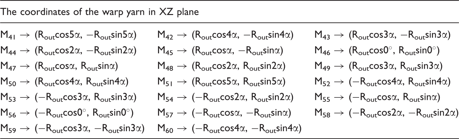
The coordinates of the warp yarn in the first orbit.

The coordinates of the warp yarn in the second orbit.

The coordinates of the warp yarn in the third orbit.
The code of the laying-in yarn in 3D tubular woven fabric.

The code of the weft yarn in 3D tubular woven fabric.

Simulation of 3D tubular woven structure
The simulation of 3D woven fabric can be simplified into yarn simulation, the yarn cross-section and the yarn path will be changed compared with the single yarn due to the influence of woven structure and weaving process, so it is necessary to determine the yarn path and yarn cross-sectional shape in the 3D model of the yarn.
To simulate the yarn, cubic B-spline curve was chosen to fit the yarn path. Compared with the sine curve and Bezier curve, cubic B-spline curve has the ability of local modification to make the yarn path smooth and actual [16, 17].
According to the tubular fabric we have woven, the yarn cross-sectional shape was regarded as circular, which kept constant along the yarn path in this paper.
The simulation was carried out according to Figure 5. When drawing a loop of the fabric structure, the diameter of the yarn was d, then the y-axis coordinates of No. −2, −1, 0, 1 layer were −2d, −d, 0, d, respectively, and thickness of the model in the y-axis direction was 4d.
In the simulation of yarns, the data points of yarns were determined according to the yarn path first, then the control points of yarns were obtained by reverse calculating in Matlab, finally the yarn model was established.
Determination of data points of the laying-in
Data points of the laying-in yarn in 3D tubular woven fabric.

Determination of data points of weft yarns
Just as the laying-in, taking the interlacing point (2, −1, −0.95) of weft yarn a and the warp yarn as an example, which represented that the weft yarn was located in No. −0.95 layer outside of No. 2 warp, and the corresponding data point was ((Rin + (−1) × d)cos4α, −0.95d, −(Rin + ( − 1) × d)sin4α). Since the weft yarn had large and more buckling, it needed more data points to make the yarn path more realistic.
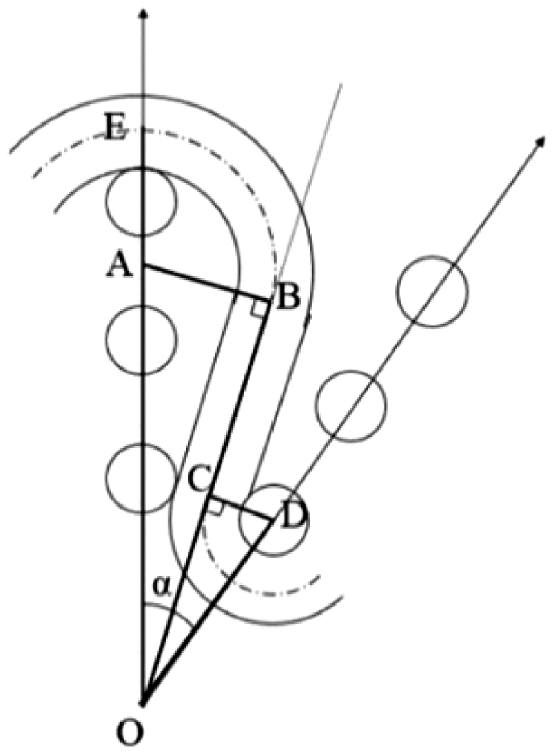
Figure 7 shows that the weft yarn path was the combination of arc and straight line, point B and point C were the tangent points of the same straight line with circle A and circle D, respectively, the OC and OB were marked as Rc and Rb, respectively, and the geometric relationship showed that
Expanding geometric model of data points of weft yarns.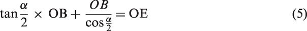
Then

Since

The difference of every two data points of weft yarns in the y-axis direction was so small that the variable quantity of every two data points was regarded to be equal in the y-axis direction, which was equal to be about 0.05/3 ≈ 0.0167. All data points were obtained according to the code of weft yarn a. For example (2, −1, −0.95) obtained three data points, namely (Rccos(4α + 0.5α), (−0.95 − 0.0167)d, −Rcsin(4α + 0.5α)), ((Rin + (−1) × d)cos 4α, −0.95d, −(Rin + (−1) × d)sin4α), (Rccos(4α − 0.5α), (−0.95 + 0.0167)d, −Rcsin(4α − 0.5α)), respectively. Similarly (43, 1, −0.9) can also get three data points, namely (Rbcos(3α + 0.5α), (−0.9 − 0.0167)d, −Rbsin(3α + 0.5α)), ((Rout + 1 × d)cos 3α, −0.9d, −(Rout +1 × d)sin3α), (Rbcos(3α − 0.5α), (−0.9 + 0.0167)d, −Rbsin(3α − 0.5α)). So every interlacing point of weft yarn a and warp yarns obtained three data points (the first and the last only need two data points).
Determination of control points of all yarns
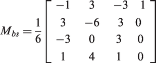
All control points of the laying-in and weft yarns in 3D tubular woven fabric were obtained by reverse calculating in Matlab according to the algorithm of computing control points of cubic B-spline curve based on the data points above [18]. The cubic B-spline function was expressed in matrix form:


N data points of the cubic B-spline (Q1, Q2,…, Qn) can determined n + 2 controlled polygon vertices (P1, P2,…, Pn+1, Pn+2). Assuming the Q1 and Qn as the endpoints of the cubic B-spline, Q2, Q3,…, Qn−1 as the piecewise connection points. Therefore the equation group of the controlled polygon vertices can be expressed as:
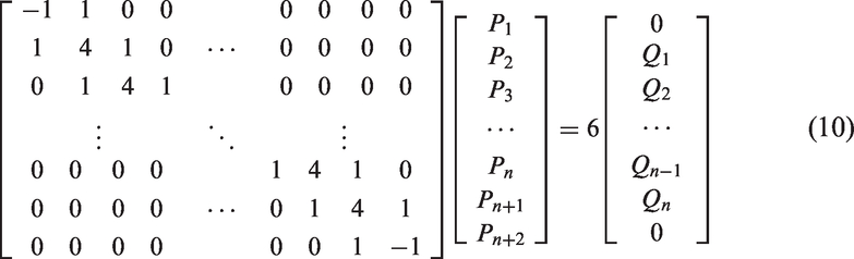
The cubic B-spline curve was set to a double vertex as the boundary condition, so a set of linear equations can be obtained:
In the end the control points (P1, P2,…, Pn+1, Pn+2) can be acquired.
With respect to the control points of the warp yarn, they were directly obtained by the data points of the two end points according to previous coordinate code of 3D tubular woven fabric as shown in Tables 1 to 3 due to its straight path. For example, the six control points of warp yarn 1 were: (0, −2.5d, −Rin), (0, −2.5d, −Rin), (0, −2.5d, −Rin), (0, 1.5d, −Rin), (0, 1.5d, −Rin), (0, 1.5d, −Rin). Similarly control points of other warp yarns were obtained.
Finally, the simulation of 3D tubular woven fabric was carried out through the programmed code and the model was shown in Figure 8.
Structural model of 3D tubular woven fabric.
In order to obtain the true state of the yarn and further to verify whether the model has reached the desired effect, the 3D tubular fabric was woven by the circular orbit method and cured with collodion, then the fabric was cut into a slicing as shown in Figure 9, what is more, for the sake of describing the weft yarn path more intuitively, the original slicing graphics was treated with Photoshop software as shown in Figure 10. It could be seen that the structure of the simulation model is similar to that of the actual fabric, and that the weft yarn path was particularly evident though it showed some defects due to the uneven force.
The fabric slicing graphics. The yarn path treated with Photoshop software.

Conclusion
In the paper, the simulation of 3D tubular woven structure was carried out through its structural analysis. Also the numerical characterization of 3D tubular woven structure was established based on the topological relation of yarns. Fabric code consisted of two parts, namely the positioning yarns code and the relationship code of positioning yarns and other yarns. In order to code the fabric, spatial rectangular coordinate system in the fabric was established first, then a system yarns chosen to be the positioning yarns from the fabric was rasterized. Finally, the topological relationship of yarns was coded. The relationship between first part of the fabric code and the second part of fabric code was similar to mapping relationship. The second part code can always find the relative first part code.
The model reflects the law of interlacing and the buckling shape of yarns in the woven fabric. However, there are some issues to be resolved in simulation of 3D woven fabric and the ultimate purpose of this study is to develop a fabric geometric simulation software that can simulate any kind of woven fabric and can achieve that a created model will be exported to the external software (such as ABAQUS, ANSYS, etc.).
Footnotes
Declaration of Conflicting Interests
The author(s) declared no potential conflicts of interest with respect to the research, authorship, and/or publication of this article.
Funding
The author(s) disclosed receipt of the following financial support for the research, authorship, and/or publication of this article: This work was supported by Shanghai Municipal Natural Science Foundation under Grant 14ZR1401000 and the Fundamental Research Funds for the Central Universities under Grant CUSF-DH-D-2017014.