
Abstract
The development of e-textiles and conductive fabrics is strongly supported by the rapid growth of wearable electronics. Unfortunately, the fast development of production technologies for smart textiles has not been followed by standard design methods and validation procedures to certificate the electro-mechanical reliability of e-textiles. Then, the design of test procedures able to control the sources of failure in combination with cross-talk effects (e.g. between load and wear, cyclic loads and current flow, etc.) is crucial. Standard tests already used for traditional fabrics are not satisfactory in predicting the lifetime of e-textiles. This paper introduces the design of innovative machine to assess the performances and reliability of smart fabrics under fully controllable conditions.
Introduction
Conductive fabrics (also known as electronic textiles or smart textiles) are textiles that feature electronics and interconnections woven into them, presenting physical flexibility and typical size that cannot be achieved with other existing electronic manufacturing techniques.
Smart fabrics may be divided in three groups according to the “level of intelligence” embedded [1]:
Passive smart fabrics: working as passive transducers, are able to sense the environment/user characteristics; Active smart fabrics: provides reactive sensing to environmental stimuli, can also integrate actuation functions and sensing devices; Very smart fabrics: are able to sense the environment, to react and to adapt their behavior to the actual conditions.
Conductive fabrics find even more applications due to the rapid development of wearable electronics. Some examples are, in medical and biomedical field, electrocardiogram (ECG) electrodes [2], electromyography (EMG) [3], and electroencephalography (EEG) [4], or to measure temperature [5]. Shape-sensitive fabrics combined with EMG sensing have been used to perform muscle fitness [6], radio frequency (RF) functionality, or assistive technology [7]. Sensors integrated into fabrics have been used to detect specific environmental or biomedical parameters such as oxygen, salinity, moisture, or contaminants [8], and fabrics containing luminescent elements have been used for biophotonic sensing [9].
In electronics and telecommunication field, it is possible to find applications as electromagnetic shields [10], distributed body-worn communication system [11], and wearable antennas [12,13]. Smart textile are also used as human interface elements [14,15], to input information [16,17] or to communicate or give information, by visible information with electroluminescent elements [18], or organic light emitting diodes (OLEDs) [19]. Dedicated fabrics have been used for power generation or storage applications [20], through piezoelectric elements [21–23] or photovoltaic elements [24]. The diffusion of applications with integrated micro electro mechanical systems (MEMS) [25–28] is also starting. Smart fabrics are fabricated by different techniques, someone related to traditional textile industry processes and others derived from specific industrial fields such as embroidering, sewing, non-woven textile, knitting, weaving, making-a-spinning, braiding, coating/laminating, printing and chemical treatments.
A huge number of combinations of these source materials result into a whole range of textiles, but sometimes garments that contain conventional cables, miniaturized electronic components, and special connectors represent the commercial output. As humans prefer to wear comfortable textiles rather than hard, rigid boxes, first efforts have been made to use the textiles themselves for electronic functions [29].
Unfortunately, the fast development of production technologies for smart textiles has not been followed by standard design methods and validation procedures to certificate the electro-mechanical reliability of final products. In fact, the electrical continuity must be preserved during the whole life of the electro-textile in presence of variable load profiles and load histories. Only few works, concerning washing tests of ECG electrodes [30] and relaxation tests of conductive knitted fabrics for breathing sensors [31,32] are available.
The first step of this process is to design test procedures where the sources of failure can be controlled and combined together to show cross-talk effects (e.g. between load and wear, cyclic loads and current flow, etc.).
Many standard tests are already used in traditional fabrics but they are not fully relevant for smart textiles where the electro-mechanical coupling is fundamental. In the next section of this paper, exhaustive review of the most important experimental procedures used for general fabrics is proposed as the starting point for the improved testing system addressed to smart fabrics, described as follows. The goal of this study is to provide the design of innovative test rig and experimental procedure to validate performances and reliability of smart fabrics under fully controllable conditions. The testing machine designed and built is able to support accelerated life tests with controlled conditions by coupling the effects of cyclic loadings equivalent to operative conditions, wear effect and electricity flow.
State of art in mechanical testing of fabrics
The traditional mechanical testing of fabrics operated in industrial laboratories and academic research centers can be divided in the following main categories:
Tensile test Tear test Seams strength test Bursting strength Abrasion Sliding resistance Compression test Pilling test.
Tensile test
Traditional tensile test machines are used for static loading of fabrics. The measurement returns force–displacement (or stress–strain) curves and ultimate force. Two rupture modes are identified: the “sharp break” and the “percentage break” [33]. In the first case (Figure 1(a)), the applied load is always increasing during the test till the ultimate load, and breaking is almost instantaneous. In the second case (Figure 1(b)), the ultimate load is lower than the maximum load and the applied force measured by the machine reduces during the last part of the test. The tensile test results also provide information about fabric stiffness and the absorbed energy.
Qualitative examples of fabrics tensile test results: sharp break (a) and percentage break (b).
Tensile tests can be conducted at imposed strain rate or imposed tensile load. Different clamping strategies are used: in the “strip test”, the width of clamps is higher than the sample width and the same load (or displacement) is imposed to all fibers; in the “grab test”, the tabs are smaller than the sample and only the fabric center is loaded. The last grabbing is used for high density fabrics and prevents fibers separation at sample edges.
In Figure 2, the two clamping strategies are reported, together with a typical machine for tensile tests on fabrics (Hengzhun HZ-1007E: 2kN max load, 500 mm/min max speed).
Left: sample clamping in tensile tests: strip test (a) and grab test (b). Right: machine for tensile tests of fabrics (Hengzhun HZ-1007E).
Tear test
The tearing strength test provides the force needed to initiate and propagate tears in the fabric with specific cuts with different geometries (Figure 3(a)). Tear tests are divided in “uniform strain rate” and “Elmendorf test”. The first one is conducted with tensile testing machines and measures the tear initiation (much higher) and propagation forces along weft and warp. Due to the fast tear propagation (around 100 mm/min), high speed detection systems are needed. In the Elmendorf test, a pendulum structure is used to apply impulsive force to pre-cut samples. The pendulum mass is varied depending on the fabric and the normative applied. The energy dissipated in the fabric during tearing can be calculated from the perturbation of the pendulum motion. In Figure 3(b), a typical Elmendorf tear tester (Thwing-Albert: 127 × 127 mm2 max sample size, 6400 g max pendulum capacity) is reported.
Example of sample preparation for tear tests (a), and machine for Elmendorf test (b).
Seams strength test
Quality and reliability of fabric products strongly depend on seams strength. This property is related to the force needed to break the yarns along the seam line, or to the force able to separate the seamed parts through the so-called seam “slippage”. The most diffused test for seams strength is the tensile test at controlled strain rate, very similar to the grab test. The test is conducted at controlled atmospheric conditions. The sample is loaded until braking, by differentiating fabric from seams breakings.
Bursting strength
The bursting test is conducted on fabrics with uniform resistance along all plane directions and replaces the tensile test along weft and warp directions. The test ends with the sample breaking (usually in the less deformable direction). Busting tests divides in “diaphragm bursting strength test” for rigid fabrics and “ball bursting strength test” for elastic fabrics (Figure 4). In both cases, the strength is related to pressure. In the first test type, a pressurized gas or fluid is applied to one side of the circular sample (held on the perimeter by circular clamp) until the breaking. The test results are the burst strength (measured in MPa) and the sample displacement (measured in mm). In the ball bursting strength test, a ball of steel is pushed against the sample with standard tensile machine at given velocity (305 mm/min in the American standard) until fabric breaking by measuring the applied force.
Schematics of “diaphragm bursting strength test”, limited to samples with small elasticity (a) and “ball bursting strength test” (b).
Abrasion
Fabric abrasion refers to the wear due to the contact with other surfaces or fabrics and is directly related to friction coefficient and material properties. The resistance to abrasion is crucial to increase the durability and reliability of fabrics and several different setups are used [33]. The most diffused abrasion test is performed by the Martindale machine (e.g. Gester GT-C13C-9), which can host 4 to 6 circular fabric samples faced to abrasive surfaces in relative motion. Variable loads are applied orthogonally to the surfaces; the abrasion resistance is proportional to the cycles prior the failure of the samples set.
Sliding resistance
Shear loads cause the relative sliding between fabric yarns, with lose of texture uniformity and comfort. The shear stiffness provides the propensity to distortion under tangential loads and provides information about the propensity to sewing and cutting. Shear hysteresis indicates the energy lost during distortion load cycles and is proportional to internal frictions between warp and weft intersections [34,35]. Tests for sliding resistance measurement are based on the scheme of Figure 5: the sample is loaded with shear forces (producing the yarn sliding) and tensile forces (to avoid sample bending and preserve the same area projection on the plane). The shear module is calculated as
Scheme of sliding resistance of fabrics under shear loads.

Compression test
With the “SiroFAST-1” system, the thickness of a 10 cm2 fabric sample is measured under pressure levels of 0.195 and 9.807 kPa, and the compression value is calculated as the difference between the two measurements (Figure 6).
Compressible substrate calculated with the SiroFAST-1 system.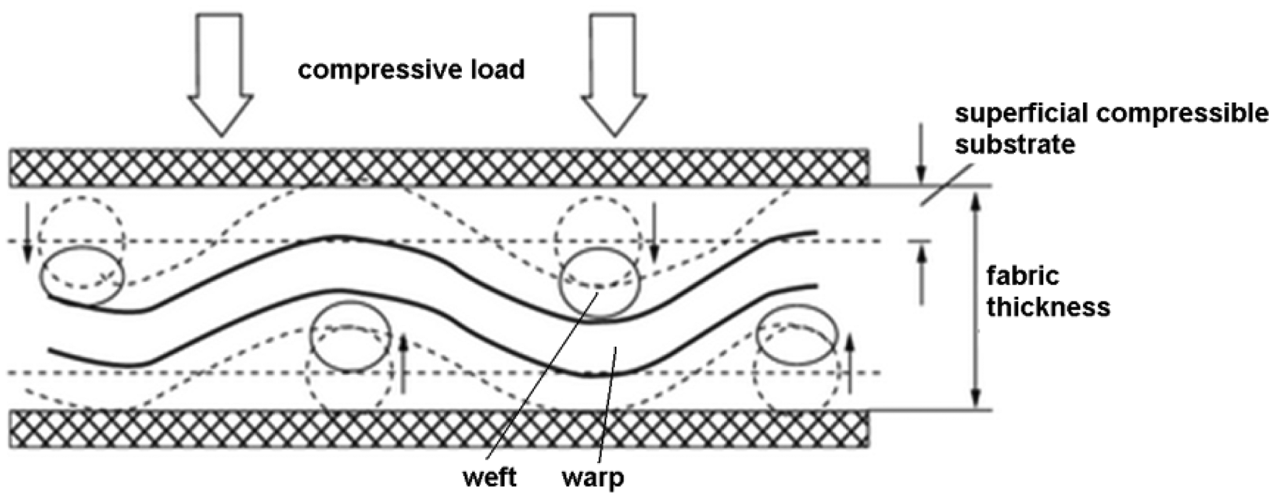
The “KES-FB3” system instead is based on the compression applied by a piston with cylindrical end of 2 cm2 diameter. The applied pressure varies between 0.1 g/cm2 to 2.5 kg/cm2, with speed varying between 0.1 and 10 mm/s. This last test is generally used to determine the compression energy, compressibility, resilience and fabric thickness.
Pilling test
The pilling effect is the fabric propensity to form balls (pills) on the surface, which is caused by repetitive friction forces and fibers spillage from the texture. It is influenced by the fabric quality and process-product characteristics. Pilling tests are performed with the Martindale machine by contacting the sample with a disc of polyurethane foam for multiple cycles. The sample surface is then analyzed with the “pilliscope”, where it is compared with five reference surfaces indicated by the standards (e.g. SLDAtlas, M227C: 6 kg weight, 430 mm height).
A more specific machine for pilling test is the “ICI Box pilling tester”, which is composed by four boxes coated with cork in the internal surface and able to rotate along the horizontal axis (e.g. Textileinstruments, TF223B: 60 r/min rotation speed, 235 mm cube boxes side). The fabric samples are wrapped on rigid cylinders and put into the boxes, where they are free to move and contact the cork and the other samples, stimulating the pilling effect. At the end of the test, the surfaces are analyzed with the pilliscope.
Design of the endurance testing system
Concept of the layout
Presently, standard mechanical tests for fabrics report the description of test machine, machine setup and test methodology. However, standard tests are generally limited to the measurement of independent properties and performances, which reduces the validation of materials and systems to the evaluation of single mechanical or physical quantities. Exhaustive test procedures and predictive models able to determine the combined electrical and mechanical reliability of fabrics are still not available. Smart fabrics provided with electrical interfaces are still not mentioned in the codified test standards and then the methods to assess their reliability are very confused. More comprehensive procedures and test methods are required to satisfy the design requirements of advanced applications involving smart fabrics.
The endurance testing system developed in this work is able to investigate the effects of multiple sources of failures, differently to the single tests normally used. It is also able to investigate the electro-mechanical coupling of smart fabrics, by measuring the electrical performances decay induced by fabric wear. The testing system, finally, can be used to perform accelerated tests able to estimate the fabrics lifetime by means of predictive models. Thanks to the peculiarities of this testing machine, the effects of loads (mean and alternate values) and number of cycles to the smart fabric lifetime could be investigated in the future.
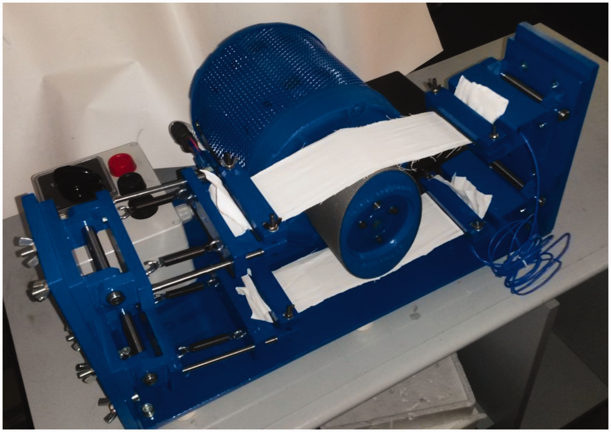
The test bench designed and built is reported in the drawing of Figure 7 and in the picture of Figure 8. The working principle of the test bench is the application of cyclic tensile and friction loads to the sample by means of the rotation of elliptical pulley (equation (1)) working as actuator. The loads are composed by mean and alternate components, which are both controllable. Depending to the sample orientation, the coupled loads can be applied along weft and warp. Pre-cut samples can be used to test tear resistance and seam strength in combination with friction-induced wear. The pulley is actuated by an AC motor (single-phase induction motor, 400 W power) and is coated with different materials with variable friction coefficients. By changing the pulley coating, abrasion tests and pilling tests can be performed.
Functional schematics of the endurance testing system including: (1) elliptical actuator; (2) electric motor; (3) control panel; (4) load cell; (5) sample clamps; (6) electric connections; and (7) fabric sample. Endurance testing system during experimental characterization of samples (in double samples configuration).
Additionally, the system is equipped with an electronic detection system able to measure the electric properties of smart fabrics through their electric connections (equation (6)). The resistivity increase of wires embedded into the fabric can be monitored during the progressive textile damaging induced by mechanical loads.
The conductive sample is held by two lateral clamps (equation (5)), which can be positioned at variable heights. Two samples can be hosted by the machine at the same time. One clamp is connected to the frame of the machine through elastic connections which are used to provide the initial adjustable preload. The load cell (Burster series 8435 ± 1 kN) (equation (4)) provides the measurement of the instantaneous load applied to the sample. The motor is controlled by the circuit scheme reported in Figure 9, which allows modifying the direction (clockwise or counterclockwise) and rotation speed (480 or 2900 r/min) of the rotating elliptical actuator. The electrical parameters associated to the smart fabric (e.g. the electrical resistance of embedded conductive wires) are measured by the ADC (analog-to-digital converter) at 50 Hz sampling rate (National Instruments USB-6001). In conclusion, this endurance testing system is able to reproduce the real operative conditions of smart (and traditional) fabrics under the effects of variable loads, providing realistic estimation of the lifetime through accelerated tests.
Fabric sample loading conditions.
By considering the anisotropic behavior of the fabric, the proposed test bench allows measuring the electric output in the same direction of the mechanical load or, alternatively, in the orthogonal direction. This can be done by modifying the sample position. Then, by repeating the measurement with two different orientations, it is possible to evaluate the 3–1 3–3 coupling coefficients of the orthotropic conductive fabric.
Forces calculation
When the sample is mounted on the testing machine Figure 10, the constant static preload


The friction force is given by


The friction force produced by the actuator rotation produces different values at the right- and left-hand sides of the sample; the ratio between the two forces [36] is

The friction force varies according to the pulley angular position θ as reported qualitatively in Figure 11. At each cycle, when the sample and the actuator are not in contact, the friction force is zero. When the sample contacts the actuator, the active phase starts (θa); here the friction force rises proportionally to the profile of the pulley. The angular amplitude of the active phase is imposed by the operator during the test setup by changing the vertical position of the clamp (h0).
Electric scheme of the motor control circuit. Qualitative profile of the friction force on the sample.

The loading duty cycle (Dc) can be defined as the ratio between the active phase θa (in radians) and the angle π (that corresponds to half cycle of the actuator)

When the duty cycle is Dc = 1, the sample is always in contact to the actuator, if Dc = 0, the sample is always unloaded.
Test bench validation: Endurance tests of smart fabrics
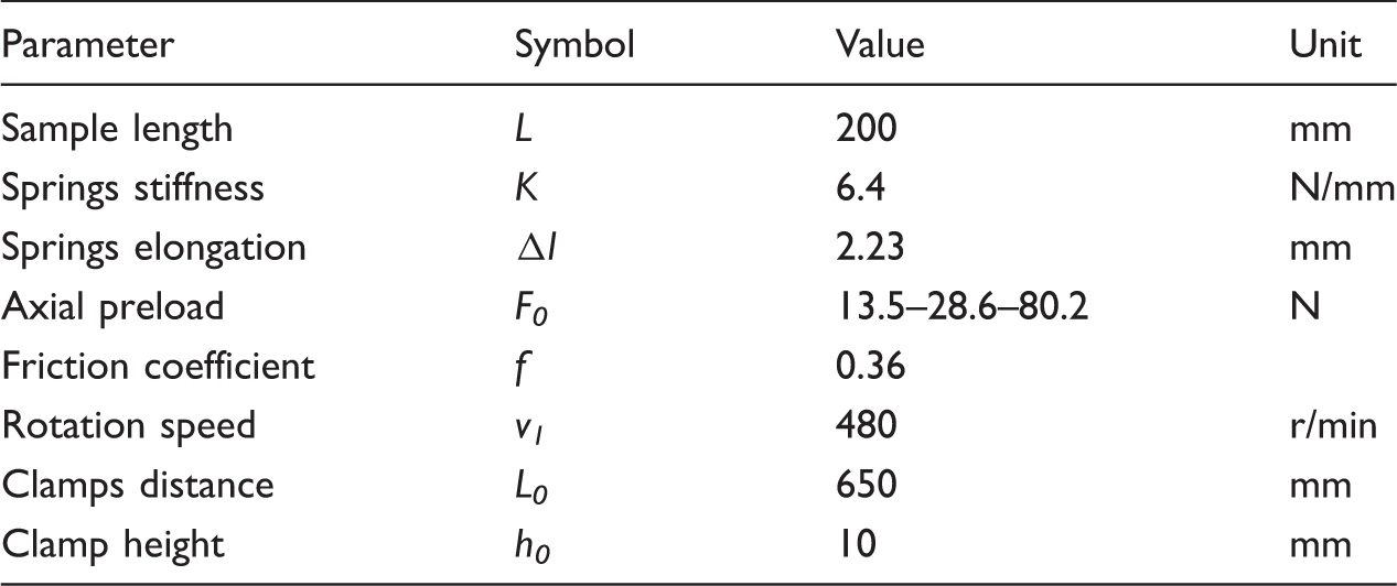
Experimental setting parameters.
The results of the endurance tests for two samples are reported in Figures 13–15 in terms of variation of the electrical resistance during time caused by the wear occurring at the actuator-fabric contact.
Detail of the conductive fabric with electric fibers at the center of the sample. Test 1: electrical resistance variation with 9.5 N axial stress and 0.36 friction coefficient as function of time (a) and number of cycles (b). Test 2 (a) and test 3 (b): electrical resistance variation with 28.6 N axial stress and 0.36 friction coefficient as function of time and number of cycles.. Test 4: electrical resistance variation with 80.2 N axial stress and 0.36 friction coefficient as function of time (a) and number of cycles (b). Progressive damage process of the conductive fabric.

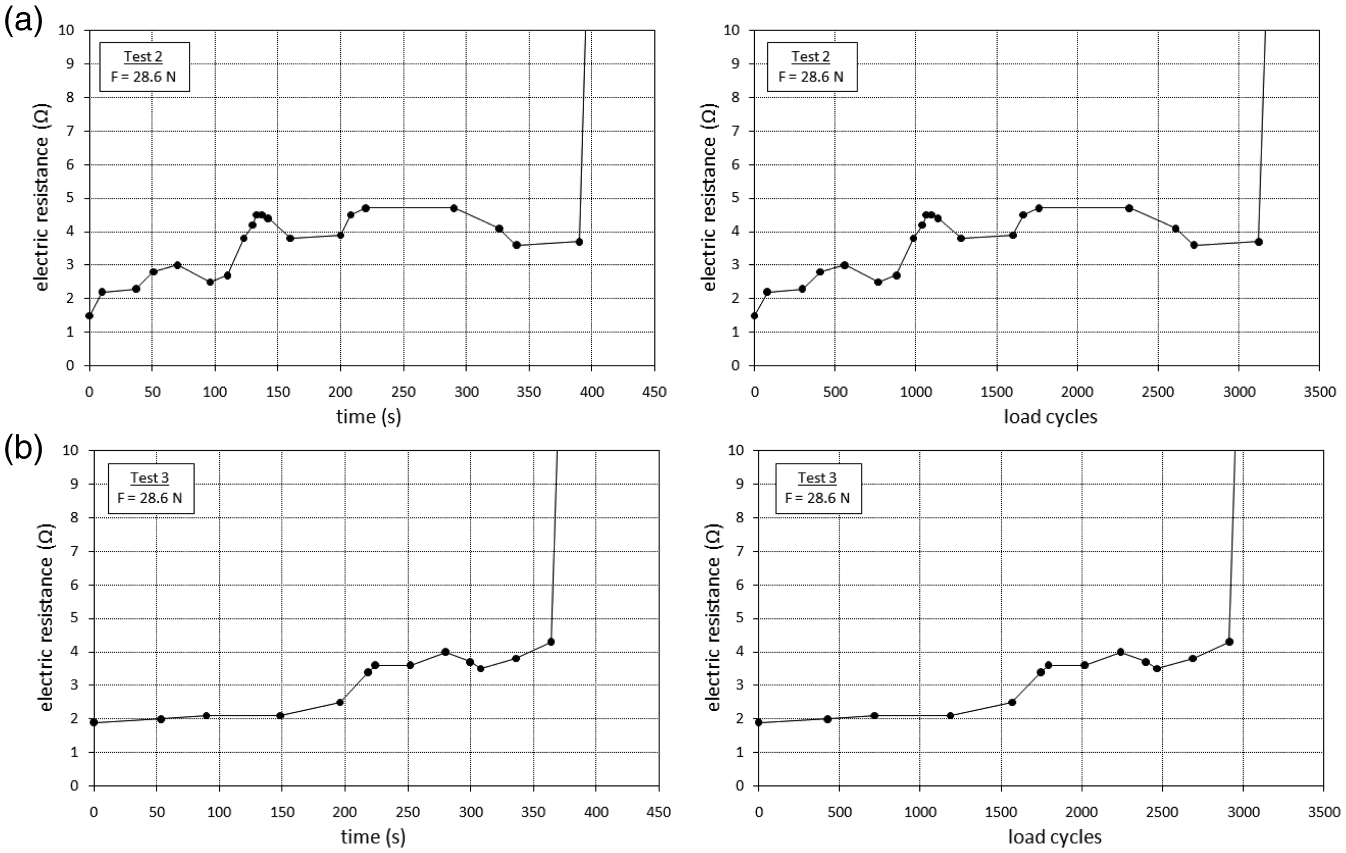
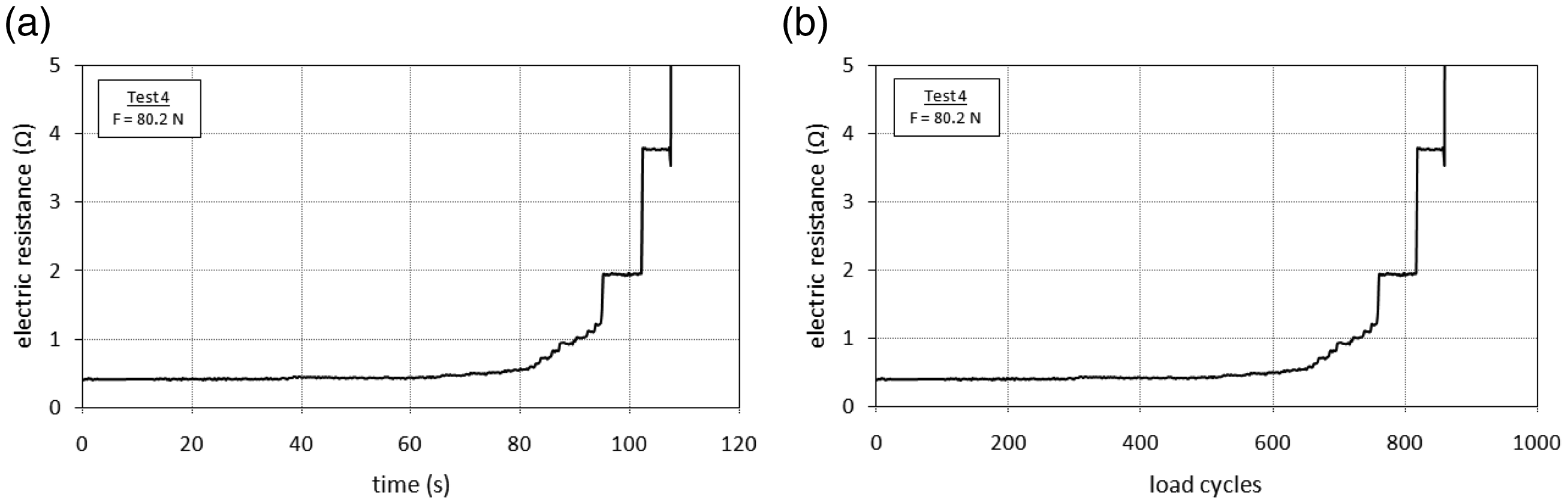

Figure 16 (a) to (h) reports the typical damage observed on samples during the test. The electric conductive fibers are embedded in the direction of the warp; during the test, the fibers aligned along the weft are initially sliding along the direction of the pulley rotation. The result is progressive accumulation of the fibers and the strip of conductive fibers. The next phase of the damaging process is the progressive deterioration of the fibers along the warp and their further rupture. When the last electric fibers are broken, the conductivity is finally lost. In Figure 17, two samples are shown after the final collapse, intended as lost of electrical conductivity. In Figure 18 the details of the damaged fibers are shown.

Two samples after the testing, and electrical conductivity lost.

Detail of fibers damaging after the test.
Conclusions
The design, fabrication, and validation of an endurance testing machine for smart fabrics have been introduced. The main peculiarity of the bench is the capability of reproducing the real operative loads and friction forces in accelerated testing modes, and the evaluation of electro-mechanical properties changes. The test bench has been conceived in order to provide cyclic loading to the sample instead of continuous friction, differently from the devices normally used for fabric testing, which does not replicate the effective operative condition. The conversion of the measured reliability data to the effective lifetime of the fabric in real operative conditions should be conducted accordingly to some major parameters as real operative frequency and operative load, and real friction coefficient between the surfaces.
Preliminary tests show the expected damage process of fabric samples under mechanical wear, in particular about the sequential collapse of the conductive fibers and the progressive increasing of electrical separation between the two terminals. The measured parameter (electric resistance) shows that the samples lose totally their conductivity under the loading and friction conditions applied. The preliminary results obtained provide initial feedback on the electro-mechanical strength of the fabric, with relation to the parameters of the weaving process.
Footnotes
Declaration of Conflicting Interests
The author(s) declared no potential conflicts of interest with respect to the research, authorship, and/or publication of this article.
Funding
The author(s) disclosed receipt of the following financial support for the research, authorship, and/or publication of this article: This study has been conducted under the grant POR-FESR 2017/2013 (Regione Piemonte, Italy).