
Abstract
In this study, single layer vascular grafts were produced by a custom designed electrospinning apparatus. Both polymer type and rotational speed of the rotating collector were varied in single layer designs. Surface morphology of the fibrous scaffolds was observed under scanning electron microscope. Fiber diameter was measured and fiber orientation was analyzed by Image J Software. Scanning electron microscope images and fiber orientation analysis results indicated that fiber orientation was improved with increased rotational speed. Ultimate tensile strength and elongation at break values of the scaffolds were tested in planar forms. In addition to the experimental analysis, statistical analysis was also realized; 22 full factorial design was adapted to the test results in order to investigate the effect of polymer type and the rotational speed on elongation at break and ultimate tensile strength values. Results have shown that both polymer type and the rotational speed of the collector significantly influenced ultimate tensile strength and elongation at break values of scaffolds tested in the radial direction. When the scaffolds tested in the horizontal direction were considered, while both factors have had a poor effect on ultimate tensile strength, they were either significant or were very close to the confidence limits. On the other hand, the interaction effect of factors had a statistically significant influence on mechanical properties of both testing directions. The achieved results supported by statistical analysis can provide a reference for further studies in designing multilayer vascular grafts.
Keywords
Introduction
The inadequacies of currently used small diameter vascular grafts, such as mismatch in mechanical properties, limited endothelization, low patency levels, late intimal hyperplasia and early thrombosis risk, have led researchers to design new scaffolds that mimic the native vessels as much as possible [1,2]. The selection of material and appropriate production technology are determinative in the constructional properties of the scaffolds. Electrospinning technology which allows production of various biopolymers and provides variety in the structure of the end product is a promising technique for production of scaffolds [3]. Polycaprolactone (PCL) and poly(-L-lactide) caprolactone (PLC) are used as raw materials for producing vascular grafts due to their good biocompatibility and slow degradation rate with improved mechanical properties [4].
The best way to create an ideal scaffold is to mimick the structural components of the target tissue; thus, it is possible to produce a vascular graft with similar mechanical and biological functions of native vessels [5]. Mechanical properties of vascular grafts are affected by polymer type and fiber orientation. When the fibers are aligned well in the direction of testing, they resist against the applied force and produce a higher ultimate tensile strength. Polymer type and elasticity of the fibrous structure are key factors that affect elongation at break values under stress. When the fibers are aligned well in the testing direction, the elasticity of the fibrous structure is influenced by polymer type. On the other hand, when fibers are randomly oriented, there are many joints which hold the structure under stress, which results in higher values of elongation at break [3]. For instance, radially oriented collagen fibers in tunica media of native artery are responsible for mechanical strength of the vessel [6]. In this regard, the radial fiber orientation achieved for scaffolds helps to improve tensile properties while promoting the proliferation of smooth muscle cells through the layer with larger pore size [5]. In a study of Yalcin et al., single layer PCL (45,000 Mn) vascular grafts produced at 4.71 m/min peripheral speeds had 0.35–0.5 MPa tensile strength in both radial and horizontal testing directions, and no significant difference was stated in the study with testing directions (p < 0.05). By increasing the peripheral speed of the rotating collector to 288.2 m/min, scaffolds having radially oriented fibers with 1 MPa tensile strength were produced. It was stated, however, that elongation at break values has decreased with improved radial fiber orientation [7]. Therefore, polymer type is also an important parameter in order to provide adequate radial elasticity and tensile strength [5].
According to the mechanical test results of PCL (80,000 Mn) vascular grafts studied by Nottelet et al. [8], tensile strength of the PCL scaffolds can vary from 2 MPa to 7.4 MPa, and strain values can vary from 200% to 1200% by changing solution parameters. In a study by Hu et al. [9], the tensile strength of PLC (70/30 molar ratio) tubular scaffolds produced at 1.41 m/min peripheral speeds was measured in a range of 3.9–7 MPa.
On the other hand, literature results have showed that porcine coronary artery has had 2.6–2.7 MPa tensile strength with 100% elongation at break values [10,11], femoral arteries have had 1–2 MPa peak stress with 63–76% elongation at break values [9], and abdominal aorta has had 1.47 MPa tensile strength in the axial direction and 5.29 MPa in the radial direction [12]. Moreover, Montini-Ballarin et al. [13] declared that the ultimate tensile strengths of coronary arteries were 0.5–3 MPa and that the tensile strength values of radial, mammary arteries, and saphenous veins were 1.5–4 MPa, while strain values of all natural vessels were in a range of 40–100%. In addition to these data, the tensile properties of electrospun vascular grafts are comparable to the natural vessels rather than stiff substitutes such as Dacron® (Ultimate tensile strength of 170–180 MPa) and Goretex® (Ultimate tensile strength of 14 MPa) currently used in bypass surgery [13].
There are several studies regarding biodegradable vascular grafts, and most of the studies stated their results with 95% confidence intervals [7,14,15]. However, experimental design studies regarding electrospun vascular grafts are rare in the literature. This study includes full factorial experimental design for tensile properties of single layer PCL and PLC vascular grafts, the details of which were discussed in our previous study [3].
Full factorial design experiments examine the effects of factors on response. The number of experiments geometrically increases with the increasing number of factors and levels [16–18]. The two-level factorial design that includes 2k experiments is the most preferred first-order design. Factorial experiments have advantages such as low cost and possibility to investigate the relation between factors [19].
In full factorial design experiments, analysis of variance (ANOVA) is used to predict and test both the main and interaction effects. It is a statistical method which analyzes the variations of the response [20,21].
In this study, 22 full factorial design was used to evaluate the effects of polymer type and the rotational speed of rotating mandrel on ultimate tensile strength and elongation at break values of vascular grafts. This study aims to improve the design of multilayer vascular grafts by integrating mechanical and statistical analysis of single layer vascular grafts.
Experimental part
Materials
Both PCL (Mn 80,000, Sigma-Aldrich, St. Louis, MO) and PLC (molar ratio 70/30 PLA/PCL, PURASORB) were dissolved in chloroform/ethanol/acetic acid (C/E/AA 8/1/1 v/v/v, Penta) at a concentration of 10% w/v solution. Avoiding polymer degradation, all solutions were stirred for 3 h and then immediately electrospun [22].
Fabrication technique
Scaffolds were produced by custom-designed electrospinning apparatus. Hypodermic needles with 0.8 mm and 1.2 mm inner diameters and a grounded stainless steel rotating mandrel (6 mm diameter, 200 mm length) were used for production. The distance between the needle tip and the mandrel was set to 200 mm, 2 ml/h feeding rate was used, and voltage was varied between 10 and 15 kV for continuous production of each polymer type. Reciprocal movement of the feeding unit was achieved pneumatically to obtain homogeneous wall thickness of the scaffolds. The rotating mandrel was empowered by a rotary tool with the rotational speed range of 5000 min−1 to 35,000 min−1, scaffolds were produced at 5000 min−1 and 15,000 min−1, and production time was 10 min for each sample.
Produced tubular scaffolds were left to dry overnight at room temperature (20 ± 3℃) and then removed from mandrel sliding manually. The tubular scaffolds were then unfolded into planar forms and cut in specified dimensions for further analysis.
Morphological analysis
Surface morphologies of the samples were observed under scanning electron microscope (SEM) after sputter coating with gold alloy. Average fiber diameters of the scaffolds were measured by Image J Software from at least 100 randomly selected fibers of related SEM images. Fiber orientation analysis was then performed by Image J Software program with Fiji Directionality Plugin, and the fiber distribution was plotted between −90° and +90° directions.
Mechanical analysis
Mechanical characterization of the samples was performed using a tensile tester (LabTest 4.050). Thicknesses of the samples were measured using a digital thickness gauge, and the tubular scaffolds were cut and unfolded into planar forms. Three specimens were prepared in 18 mm × 10 mm dimensions in horizontal (H) and radial (R) directions. A 50-mm/min strain rate was set to the equipment and the distance between gauges was adjusted to 8 mm while considering the dimensions of the sample. Results were evaluated regarding ultimate tensile strength and elongation at break data with standard deviations (SD).
Statistical analysis
Factors and levels.

Full-factorial experimental design layout.

In ANOVA tables, the degrees of freedom, sum of squares, and mean squares are represented by df, SS, and MS, respectively. F value is calculated by dividing the MS of the variable by the MS of the error. The area under the appropriate null-sampling distribution of F that is larger than the observed F-statistic indicates the p value. According to the 95% confidence interval, the parameters which have p values less than 0.05 have a statistically significant effect on the response of the experimental layout [23].
Results and discussion
Morphological analysis
Tubular scaffolds with lengths up to 100 mm, inner diameters of 6 mm, and wall thicknesses in a range of 200–300 µm were successfully fabricated. The length of the scaffolds was controlled by adjusting the length of the reciprocal movement of the spinning electrode, while the wall thickness of the scaffolds was controlled by the duration of the electrospinning, and the fiber orientation was controlled with rotational speed of the mandrel.
SEM images of PCL and PLC scaffolds are illustrated in Figure 1. According to the SEM images, both PCL and PLC surfaces are free of beads and composed of continuous micro fibers. Moreover, randomly distributed fibers were produced at 5000 min−1 while radially oriented fibers were achieved at 15,000 min−1.
SEM images of (a) PCL scaffolds produced at 5000 min−1; (b) PCL scaffolds produced at 15,000 min−1; (c) PLC scaffolds produced at 5000 min−1; (d) PLC scaffolds produced at 15,000 min−1 and fiber directionality analysis of (d) PCL and (e) PLC scaffolds. Green (dotted) lines belong to the scaffolds produced at 5000 min−1, while yellow (continuous) lines belong to the scaffolds produced at 15,000 min−1. Additionally, 0° indicates the radial direction and 90° indicates the horizontal direction.
Average fiber diameter of PCL has decreased from 2.96 ± 0.88 µm to 2.50 ± 0.85 µm when the rotational speed has increased. The reduction in fiber diameter can be explained by the existence of mechanical stress with improved fiber orientation [24]. In contrast to PCL, the average fiber diameter of PLC slightly has increased from 4.01 ± 1.01 µm to 4.59 ± 1.42 µm when the rotational speed has increased. The unexpected increment can be derived from the extreme elastic behavior of PLC polymer [3]. Although PLC fibers were oriented at 15,000 min−1 radially under mechanical stress, the fibers slightly recovered themselves after being removed from the rotating mandrel, which resulted in thicker fibers by creating a wavy structure (Figure 1(d)).
Mechanical analysis
Stress–strain curves of the samples have been given in Figure 2. In Figure 2, scaffolds produced at 5000 min−1 and tested in the horizontal direction were compared with scaffolds produced at 15,000 min−1 and tested in the radial direction to see the distinct differences.
Stress–strain curves of PCL and PLC scaffolds produced at 5000 min−1 and 15,000 min−1.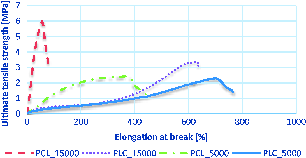
Average ultimate tensile strength and elongation at break values of scaffolds.

Average ultimate tensile strengths of PCL planar samples produced at 5000 min−1 were 2.88 MPa ± 0.67 MPa in radial and 3.02 ± 0.82 MPa in horizontal directions. This can also be seen in fiber orientation analysis, since there is no fiber orientation at 5000 min−1 for PCL (Figures 1 and 2). Similarly, average ultimate tensile strengths of PLC samples produced at 5000 min−1 were around 2.70 ± 0.01 MPa and 2.53 ± 0.20 MPa in the radial and horizontal directions, respectively. PCL samples produced at 15,000 min−1 have had an average ultimate strength of 6.76 ± 0.78 MPa in the radial direction with comparatively lower (80%) elongation at break values (Figure 2). In contrast, in the horizontal direction, PCL samples have an average ultimate tensile strength of 1.62 ± 0.16 MPa with 407% elongation at break values, which prove the fiber orientation analysis results of PCL produced at 15,000 min−1 (Figure 1). Because of its improved elastic properties, the highest elongation at break value was achieved with PLC samples produced at 15,000 min−1 (around 800%) in the horizontal direction (Figure 2). Average ultimate tensile strengths of PLC produced at 15,000 min−1 were 3.35 ± 0.62 MPa in radial and 2.86 ± 0.36 MPa in horizontal directions. These data have showed that PLC fibers were oriented in the radial direction but not as much as PCL fibers (Figure 1). Mechanical properties of both PLC and PCL scaffolds were in the range of results that were stated in the literature [8,9]. Although these results matched with the mechanical properties of native vessels [9–13], multilayer designs including both randomly distributed and radially oriented fibrous layers will be more promising while resembling the structural and functional properties of native vessels [3].
Statistical results
Tensile strength
ANOVA response tables of ultimate tensile strength of samples.

SS value indicates the effect of the parameter on the result, it means that if a parameter has a high-SS value, it has a large influence on the result [25].
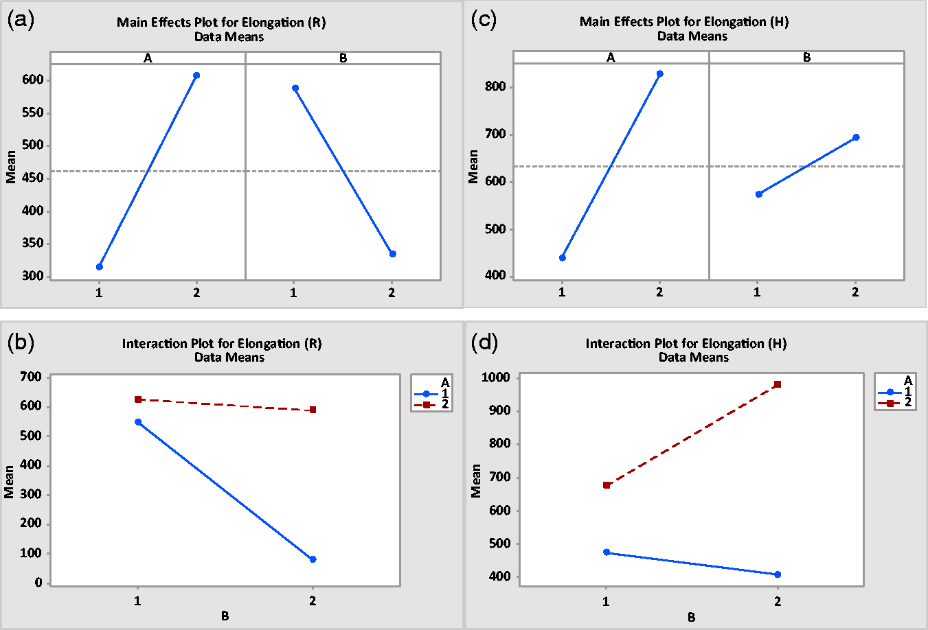
Based on SS and p values of samples, both polymer type (p = 0.001) and the rotational speed (p < 0.05) have significant effect on samples tested in the radial direction (Table 4(a)). However, samples tested in the horizontal direction were influenced neither from polymer type (p = 0.281) nor the rotational speed (p = 0.141) (Table 4(b)). The radially aligned fibers were located against to the horizontal test direction. Therefore, their ultimate tensile strength was similar to the results of randomly distributed fibers; thus, the rotational speed has no significant effect on tensile properties. On the other hand, in the radial test direction, the ultimate tensile strength of oriented fibers was significantly higher than randomly distributed fibers because all fibers were aligned in the test direction and they bear the applied force. This situation is also seen from main effects plot (Figure 3(a) and (b)).
Main effects plots of ultimate tensile strength of samples tested in (a) radial and (b) horizontal directions and interaction plots of samples tested in (c) radial and (d) horizontal directions.
When the fibers are aligned well in the direction of testing (refers to the productions at 15,000 min−1 in this study), they resist against the applied force based on the polymers’ characteristic properties [3]. For instance, when the second level of factor B was kept constant (15,000 min−1), the first level of factor A (PCL) had higher ultimate tensile strength value (6.76 MPa) in the radial direction than the second level of factor A (PLC) (3.35 MPa); thus, the polymer type influences the tensile properties (dominant tensile strength characteristics of PCL in comparison to PLC) (Figure 3(a)). On the other hand, when the first level of factor A was kept constant (PCL) at 15,000 min−1, the ultimate tensile strength in the radial direction was measured as 6.76 MPa, while at 5000 min−1, it was 2.88 MPa; thus, the rotational speed influences the tensile properties.
However, in the horizontal direction, neither polymer type nor the rotational speed has had statistically significant effect on ultimate tensile strength. For instance, when factor A was kept constant at level one (PCL), ultimate tensile strengths of samples produced at 15,000 min−1 and 5000 min−1 and tested in the horizontal direction were 1.62 MPa and 3.02 MPa, respectively. Similarly, when factor A was kept constant at level two (PLC), ultimate tensile strengths of samples produced at 15,000 min−1 and 5000 min−1 and tested in the horizontal direction were 2.53 MPa and 2.86 MPa, respectively (Table 3). These results represented the poor effect of the rotational speed on tensile properties tested in the horizontal directions (p = 0.141). On the other hand, when the rotational speed was kept constant at 5000 min−1, ultimate tensile strengths tested in the horizontal direction were 3.02 MPa for PCL and 2.53 MPa for PLC. Similarly, at rotational speed of 15,000 min−1, PCL had an ultimate tensile strength of 1.62 MPa, while PLC had 2.86 MPa in the horizontal direction (Table 3). These examples have also shown that the effect of polymer type on horizontally tested samples tensile properties was not statistically significant (p = 0.281). In contrast to radial test direction, in the horizontal test direction, constructional effect was more dominant than polymer type.
If the factor lines of the interaction plots intersect, it means that these two factors have a combined effect on the response rather than their main effects [26]. Figure 3(c) and (d) shows that two factors intersect with each other in both test directions. Furthermore, Table 4 shows that the interaction between polymer type and the rotational speed (A × B) influenced the ultimate tensile strength of both samples tested in radial (p = 0.001) and horizontal (p = 0.031) directions.
Elongation at break
ANOVA response tables of elongation at break of samples.

Main effects plots of elongation at break values of samples tested in (a) radial and (b) horizontal directions and the interaction plots of samples tested in (c) radial and (d) horizontal directions.
Although both factors were significantly effective in the horizontal testing direction, polymer type has a greater influence compared to the rotational speed (Table 5). Since the radially oriented fibers were located against to the test direction, they have shown similar behavior with the samples composed of randomly oriented fibers. The p value of factor B of sample tested in the horizontal direction was 0.049 which is very close to the significance value of 0.05. When factor A was kept constant at first level (PCL), average elongation at break result of samples produced at 15,000 min−1 was 406.63 ± 77.98% and was 474.21 ± 70.39% for samples produced at 5000 min−1, which proves that the p value is very close to the limiting value (0.05). In contrast, when factor B was kept constant at 15,000 min−1, average elongation at break value for PCL was 406.63 ± 77.98% and was 982.13 ± 67.76% for PLC, in addition, since the p value is very low (p < 0.05), the significance of polymer type is supported. The main effects plots also show that the difference between mean values of two levels of factor B was lower compared to other factors and this situation has resulted in higher p values (Figure 4).
Considering the interaction plots, factor lines were not parallel to each other and had the tendency to intersect at a point. The p values of A × B were 0.024 and 0.007 for radially and horizontally tested samples, respectively.
Conclusion
In this article, both PCL and PLC single layer vascular grafts were successfully produced by a custom-designed electrospinning machine modified by a rotary tool to reach high rotational speeds (up to 15,000 min−1). Increment of fiber orientation with increasing rotational speed was demonstrated with SEM and Image J fiber orientation analysis.
According to the mechanical performance test results, while the ultimate tensile strength of PCL scaffolds has risen with increasing rotational speed, it has remained steady for PLC scaffolds, and this has proved the fiber orientation test results. While both polymer type and the rotational speed of the collector were significantly effective on ultimate tensile strength and elongation at break values of scaffolds tested in the radial direction, in the horizontal direction it was observed that factors are not statistically effective on ultimate tensile strength. Elongation at break values of samples tested in horizontal direction were either significant or very close to the limiting value (p = 0.05). Rather than individual effects of each factor, the composed effect of the all factors has become an important task for engineered designs. The combined effect of polymer type and the rotational speed of the collector have had a statistically significant effect on single layer vascular grafts’ mechanical properties which should be taken into consideration when designing a multilayer vascular graft designs for mimicking the native vessel properly.
Footnotes
Acknowledgements
The authors would like to express their sincere thanks to Prof. RNDr. David Lukas, CSc. and RNDr. Jana Horakova, PhD. from Technical University of Liberec, Department of Nonwovens, and Nanofibrous Materials for offering their laboratory opportunities and sharing their experiences.
Declaration of Conflicting Interests
The author(s) declared no potential conflicts of interest with respect to the research, authorship, and/or publication of this article.
Funding
The author(s) disclosed receipt of the following financial support for the research, authorship, and/or publication of this article: This study was funded by TUBITAK (Grant No. 214M089) and ITU BAP (Grant No. 39343).