
Abstract
A large number of patients suffer from vascular diseases, resulting in the need for bypass surgery. Since there are still limitations in the replacement of small diameter vascular grafts, the need and demand for developing more desirable grafts is increasing day by day. In this study, polycaprolactone small-diameter (6 mm) vascular grafts were produced successfully using custom-designed electrospinning apparatus. Radial fiber orientation was achieved by increasing the rotational speed of the collector. The morphological, structural, mechanical, and biological properties were examined. The results show that oriented scaffolds with 2 µm average fiber diameter provide 1 MPa ultimate tensile strength in the radial direction. The pore size area was found to be adequate in the oriented samples required for cell proliferation and diffusion through the tunica media. In vitro biocompatibility of the grafts was proven with 3T3 mouse fibroblasts. After cell seeding, the oriented fibers serve as a cue for radial cell alignment. An understanding of electrospun material parameters together with knowledge of native blood vessel structures and properties is a considerable part in designing small-diameter vascular grafts.
Introduction
Cardiovascular diseases (CVDs) are the number one cause of death globally: more people die annually from CVDs than from any other cause [1]. Conventional therapeutic strategies include angioplasty, endoarterectomy, or bypass grafting [2]. Currently available synthetic grafts work well in the replacement of large diameter (>6 mm), high-flow vessels. However, they fail for small diameters due to acute thrombogenicity of the graft, anastomotic intimal hyperplasia, aneurysm formation, infection, and progression of artherosclerotic disease [3]. Autologous arterial and venous grafts seem to be the best choices for small-diameter bypass grafts, but in many patients their usage is limited for reasons such as vasospasm, limited length, poor quality, and prior use [4,5]. Considering these requirements with the large number of patients in need of replacement grafts, the demand for an alternative small-diameter graft is enormous and has driven scientists to search for new materials. The ideal vascular graft has to possess mechanical strength, compliance, biocompatibility, nonthrombogenicity, nontoxicity, nonimmunogenicity, and off-the-shelf availability [6,7]. The issue of small-diameter blood vessel graft remains a major challenge yet to be overcome in the production of appropriate substitutes. To develop a suitable scaffold for small diameter blood vessel replacement, the native structure and properties has to be considered. The native artery is an extremely complex multilayered tissue composed of a number of different extracellular matrix (ECM) proteins and cell types. In order to withstand the high flow rate, high pressure, and pulsating nature of blood flow, an artery is comprised of three distinct layers called the tunica intima, tunica media, and tunica adventitia. Each of these layers has a different composition and plays a different physiological role [8]. The composition varies in cell types as well as in the morphology of ECM. The intimal layer of the blood vessels consists of a single layer of endothelial cells (ECs) lining the vessels internal surface [9]. This layer is in contact with the bloodstream therefore it provides a critical barrier to platelet activation. The endothelium has many functions. It provides the vessel with a dynamic layer of cells which, moreover, displays antithrombotic properties in their resting state. This is achieved by physically preventing elements in the blood to come into contact with prothrombotic elements in the subendothelium and by active synthesis of various mediators [10]. ECs are comprised of a laminin-rich basement membrane which lines under the endothelial interior surface of the blood vessel. The ECM in the tunica intima provides critical support for vascular endothelium and it influences ECs migration, invasion, survival, and organization. ECs are attached to ECM by cell-surface integrins. Cell adhesion can be supported by interstitial fibrin and collagen I [11]. The tunica media begins in the internal elastic lamina that separates the tunica intima and the tunica media. The middle layer is composed of smooth muscle cells (SMCs) with many functions, including vasoconstriction and dilatation; synthesis of various types of collagen, elastin, and proteoglycans; and elaboration of growth factors and cytokines [10]. The tunica media is organized into concentric lamellar units composed of elastic fibers and SMCs, separated by an interlamellar matrix containing collagens, proteoglycans, and glycoproteins [12]. Collagen fibers provide tensile stiffness whereas elastin gives the tube the required elastic properties. Compressibility of the vessel and the irreversible deformation against pulsating blood flow are provided by proteoglycans and glycoproteins. The composition of ECM in the tunica media regulates the activity and phenotype of SMCs [13]. In vitro studies confirm the involvement of ECM–SMC signaling in establishing and maintaining the mature tubular structure [12]. Finally, the adventitia extends beyond the external elastic lamina and is composed mainly of randomly arranged collagen fibers and fibroblasts [8,14,15]. This outermost layer is nourished by vasa vasorum, thin capillaries providing an important source of nutrition [16]. When designing a multilayer structure for vascular grafts, it is important to mimic the topographical, morphological, and mechanical properties of each layer as much as possible [17]. For this purpose, an electrospinning technique was utilized as the main technology. An electrospun nanofibrous structure provides a biomimetic cellular environment which resembles the ECM of native blood vessels. Moreover, the high surface-to-volume ratio of these structures provides potential anchoring points for cell attachment [4,18]. To achieve the different structures of the above-mentioned layers, various modifications to the electrospinning process were employed. The AVflo™ Vascular Access Graft is the first commercial vascular access graft to exploit the unique properties of electrospun nanofabrics. Since it is made of polycarbonate urethane which is a biocompatible synthetic polymer, it has improved patency levels. On the other hand, the use of multilayered nanofibrous structure provides many advantages one of which is easy suturing that offers a solution for hemodialysis patients [19].
The choice of material is another crucial task that has to be considered. Biodegradable materials provide a key advantage. As the material degrades hydrolytically over time, cells continuously infiltrate the matrix, producing collagen, elastin, and proteoglycans to replace the degrading material. Eventually, a fully functional artery is created composed of autologous smooth muscle and ECs. Therefore, long degradation time is one of the most important properties for the biopolymer that provides prolonged mechanical backbone for cells to infiltrate and low inflammatory response [20].
Polycaprolactone (PCL) is a promising candidate for vascular grafts due to its bioactivity for both ECs and SMCs, nontoxicity, and comparatively high elastic behavior. In addition to that, hydrophobic nature and the high level of crystallinity of PCL scaffolds result in a long degradation time (more than 18 months in vivo [21]) which provides a prolonged mechanical support for cell infiltration [10,20,22].
There are many studies which call for the usage of electrospun PCL for vascular grafts. Lee et al. produced scaffolds from the blends of biodegradable polymers (PCL, poly-L-lactic acid (PLLA), poly(lactic-co-glycolic acid) (PLGA), poly(L-lactide-co-caprolactone) (PLCL)) with structural proteins (elastin and collagen). Based on the results it can be said that long-term patencies of the scaffolds consisting of PCL are better in comparison with other scaffolds produced from biodegradable polymers (PLLA, PLGA, PLCL) [23]. On the other hand, Wise et al. indicates that the mixture of PCL with structural proteins improves the mechanical strength [24]. In a study of Gaudio et al., the use of chloroform as a solvent for PCL results in micro-scaled fibers (3.6 ± 0.8 µm) which leads to better SMCs viability, improved interfacial surface between cells and fibers, and promoted cell colonization in comparison with nanofibrous web produced by PCL in DMF:tetrahydrofurane (1:1) solvent system [25].
Beside in vitro studies, the in vivo implantation of PCL vascular grafts in rats was successfully realized by Wang et al. [26], Valence et al. [21], Pektok et al. [27], and Nottelet et al. [28] with the results of adequate long-term patency levels against to thrombosis risk.
This study aims to design the best copy of native vessel ECM. We presume that the internal morphology of such a graft, mimicking the native ECM, will facilitate cell ingrowth and maintain all its essential functions. In this respect, pore size and fiber orientation become crucial design parameters for vascular grafts. Ju et al. produced two layered scaffolds with differing pore sizes from PCL/collagen solution. Both SMCs and ECs were seeded on the scaffold and results indicate that different pore sizes can be produced by varying fiber diameters. Moreover it is stated that the increase in fiber diameter enables improved SMCs diffusion whereas less than 1 µm pore size was found insufficient for SMCs infiltration [4]. On the other hand, Lee et al. defined suitable pore sizes for SMCs infiltration in the range of 100–400 µm [29]. Radial fiber orientation is essential for SMCs infiltration while mimicking tunica media. Hu et al. produced tubular scaffolds from PCL in Dichloromethane (DCM)/Dimethylformamide (DMF) solution by using differing rotational speeds (250, 1000, and 1500 r/min) for 10 cm diameter cylindrical collector. For radial fiber orientation, minimum 200 m/min peripheral speed was found to be required [30]. Edwards et al. similarly studied on radial fiber orientations for PCL/diclorethane solution. For 3.2 cm collector diameter, peripheral speed of collector was varied from 0 to 480 m/min. Results show that fibers are not exposed to a notable extension force when less then 120 m/min speed was used. 150 m/min was defined as an optimum speed for fiber orientation achievement whereas mechanical fiber deformation was observed at 300 m/min [22].
In this study, tubular scaffolds were produced using custom-designed electrospinning apparatus with a needle spinning electrode and modified rotating mandrel type collector. PCL in chloroform:ethanol solvent system with 18% weight ratio was chosen and predetermined electrospinning production parameters were used in the light of our previous works [31,32]. Radial fiber orientation was achieved by varying the rotational speed of the mandrel in order to improve the mechanical performance and cell organization. Fiber diameter distribution as well as pore size area and porosity analysis was examined to evaluate its suitability for cell proliferation and diffusion through the tunica media. The relationship between the orientation of fibers and cells was confirmed in vitro by seeding 3T3 mouse fibroblasts. This study aims to constitute a considerable step forward in designing multilayered vascular graft.
Materials and methods
Histological preparation of native blood vessels
Small-diameter blood vessels were obtained from Liberec Regional Hospital. The carotid artery was fixed in formaldehyde followed by gradual dehydration with alcohol and soaking in toluene. Samples were embedded in paraffin and 3 µm sections were prepared for histological analysis. After removal of the embedded resin, the samples were stained with hematoxylin eosin (H&E) in order to see the cells (a), Van Gieson staining in order to see the collagen (b), and Acetic orcein in order to see the elastin fibers (c). The stained samples were placed on slides and analyzed through a Nikon ECLIPSE Ti-E/B light microscope. A thin section of the embedded tissue was prepared directly on the target for further scanning electron microscope (SEM) analysis.
Polymers
Polycaprolactone (PCL, Mn 45000, Sigma-Aldrich, St. Louis, MO) was dissolved in chloroform/ethanol (9/1 v/v, Sigma-Aldrich) at a concentration of 18 w/v % solution. Since chloroform evaporates very fast, polymeric solution could get concentrated quickly. The addition of ethanol slows down the evaporation rate of chloroform and improves the spinnability of PCL. The solution was stirred for 8 h and then immediately electrospun.
Electrospinning
The custom-designed electrospinning apparatus consisted of a positive high-voltage power supply (Matsusada Precision Inc., Japan), a syringe pump (Model NE-1000x; New Era Pump Systems Inc., USA), a 10 ml plastic syringe, a hypodermic needle with 0.6 mm inner diameter, and a grounded stainless steel rotating mandrel (6 mm diameter, 20 cm length). Reciprocal movement of the needle spinning electrode was achieved using a sliding holder powered by a step electromotor or alternatively by a drilling machine. The length of the slide was limited to 10 cm while its peripheral speed was fixed at 0.6 m/min during production. A diagram and a photograph of the electrospinning apparatus is shown in Figure 1.
Diagram (a) and picture (b) of the electrospinning apparatus: A high voltage is applied between the needle tip (3) and the mandrel type collector (4). The polymer solution is delivered to the needle tip at a constant feed rate using a syringe pump (1) attached to the sliding unit (5). An electric field is generated by the high voltage power supply (2). Finally a continuous web is collected on the rotating mandrel (4) in a tubular form.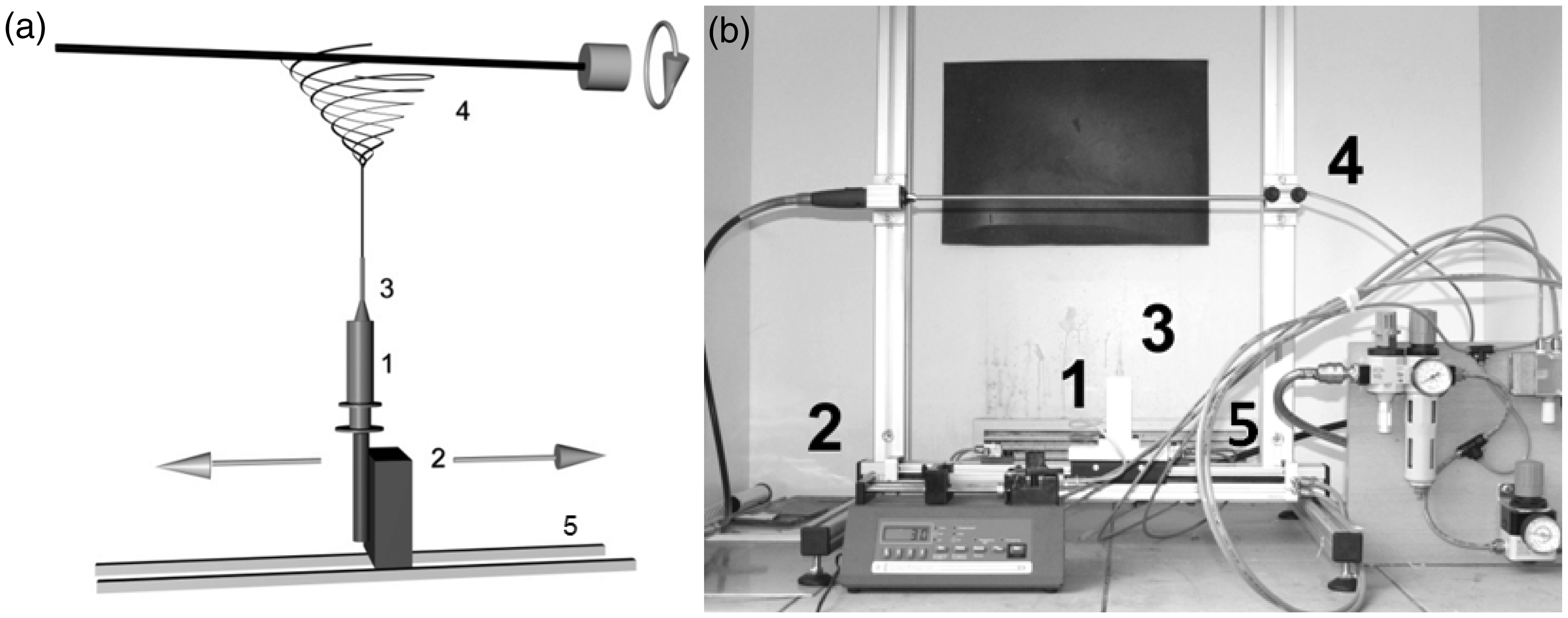
Scaffold fabrication
The tubular PCL scaffolds were produced using custom-designed electrospinning apparatus. The production parameters were set as follows: applied voltage was 7.5 kV and the feed rate was 2.0 ± 0.5 ml/h. The temperature and relative humidity were 20 ± 3℃ and 34 ± 4%, respectively. The following rotational speeds of the mandrel were used: 250, 5000, 10,000, and 15,000 r/min (e.g. peripheral speeds were 4.71, 94.2, 188.4, and 282.6 m/min). The collector was driven by a step motor up to 250 r/min. For higher rotational speeds (5000, 10000, 15000 r/min), a drilling machine was integrated to electrospinning apparatus to empower the collector.
Finally, the tubular graft was left to dry overnight at room temperature (20 ± 3℃). Then PCL fibrous tube could be obtained from the rod by pushing manually. After removal from the mandrel, the specimens were cut up for the various analyses as described in the following sections.
Morphological analysis
The tubes were cut to obtain 0.5 cm × 0.5 cm flat samples and both inner and outer sides of the tubes were analyzed. Specimens were placed in a holder, coated with gold, and analyzed using a SEM from Phenom-World (FEI Company, USA). The average fiber diameter, fiber orientation distribution, pore size area, and porosity analysis were carried out using NIS Elements Software System (Nikon Instruments Inc.). Pore sizes were also evaluated using the Bubble method. These analysis techniques are based on different measuring principles therefore their results were compared and the differences were discussed.
NIS Elements Software
The average fiber diameter, the orientation of the fibers, porosity, and pore size area were measured using NIS Elements Software for all rotational speeds (250, 5000, 10,000, and 15,000 r/min). The average fiber diameter was measured from 100 randomly selected fibers from three different SEM images. Fiber orientation was analyzed manually by drawing lines in the directions of 100 randomly chosen fiber elements. The reference line, that is the zero degree direction, is identified as the radial direction of fibers produced. The angle between the reference line and the line drawn tangentially to a fiber axis was recorded. Finally, the fiber orientation distribution in the range from −90° to +90° was plotted in the graph. Porosity and pore size area were evaluated by automatic pore detection from six SEM photos. The average pore size, the minimum and the maximum values, the standard deviation, and also the porosity were recorded. All measurements were realized by SEM images of 1000× magnification.
The Bubble method
The maximum and average pore sizes were determined using the Bubble method testing apparatus (ASTM F316 – A3, CR.). The Bubble method is a nondestructive way to determine the diameter of the largest pore size of a fibrous membrane and the mean pore size. The testing range is from 0.2 to 200 µm. For this study, the sample size was reduced from a standard value of 19.6–1 cm2 in order to adapt the testing conditions for the tubular scaffolds. This technique involved two steps: dry and wet measurements. In dry measurement, samples were placed in the housing of the testing unit and exposed to gradually increasing gas pressure (pressure gradient range from 0 to 0.6 MPa). The data were recorded by a software system. Then, for wet measurement, samples were impregnated with a wetting liquid (in this case, mineral oil with a surface tension of 49 mN/m) and the increasing gas pressure was applied again. When a constant flow of rising bubbles was observed on the top side of the sample, the gas pressure p (Pa) was recorded. The maximum pore size diameter D (m) was determined from the following equation

Mechanical characterization
Mechanical characterization of the tubular scaffolds was carried out using a tensile tester (Labor-Tech s.r.o., CR). The thickness of the samples was measured using a digital thickness gauge (Nova Technology s.r.o., CR). The tubular scaffolds were cut and unfolded into a planar form. Four specimens were prepared in 18 mm × 10 mm dimensions in axial (90°), radial (0°), and 45° directions. The stroke rate and the gauge length were set to 3 mm/min and 10 mm, respectively.
Cell sources and seeding
Prior to cell seeding, the scaffolds were cut into round segments of 6 mm in diameter and sterilized by immersion in 70% ethanol for 30 min followed by double washing in a phosphated buffer saline (PBS, Lonza). Mouse 3T3 fibroblasts (ATCC, USA) were cultivated in Dulbecco’s Modified Eagle Medium (DMEM, Lonza) supplemented by 10% fetal bovine serum (Lonza) and 1% penicillin/streptomycin/amphotericin B (Lonza). The cells were placed in a humidified incubator with an atmosphere of 5% CO2 at 37℃. When the cells became confluent, they were suspended using trypsin–Ethylenediaminetetraacetic acid (EDTA) solution (Lonza). The number of cells was determined using a Luna™ cell counter (Logos Biosystems). The fibroblasts were seeded on the scaffolds placed in 96-well plate at a rate of 5 × 10³ per well plate. The experiment took 14 days and the medium was changed three times a week during this period.
(3 -(4.5-dimethylthiazol-2-yl)-2.5-diphenyl-2H-tetrazolium bromide) (MTT) assay
The viability of the cells seeded on the scaffolds was analyzed using an MTT test after 1, 4, 7, and 14 days of the culture period. MTT had been reduced to the purple formazan by mitochondrial dehydrogenase in the cells indicating normal metabolism. MTT solution (50 µl) was added to 150 µl of DMEM and the samples were incubated at 37℃ for 4 h. Violet crystals of formazan were formed and were dissolved using acidic isopropanol. The optical density was measured using an ELx808 Absorbance Microplate Reader (Biotec) at the following sample and reference wavelengths (λsample 570 nm, λreference 690 nm). Each measurement was taken in quadruplicates; finally the average wavelength (λsample 570 nm − λreference 690 nm) and its standard deviation were calculated and depicted in the graph.
Fluorescence microscopy analysis
After 1 day of cultivation, the samples were washed with PBS and fixed in frozen methanol for 30 min. Then, PBS washing followed staining with propidium iodide for 10 min in the dark. Images of stained cell nuclei were captured using a Nikon ECLIPSE Ti-E/B fluorescence microscope (magnification 400×) and analyzed using NIS Elements. Twenty cell nuclei from each sample were chosen and their maximum and minimum Feret’s diameters were measured. The elongation of the cell nuclei was determined from the ratio of their maximum and minimum Feret’s diameters. The ratio close to 1 indicates no cell elongation, while a ratio greater than 1.5 indicates cell nuclei elongation along the fiber axes. To support the data, cell elongation was also investigated with Image J’s function Aspect Ratio (AR).
SEM
After 7 days of cultivation, the samples were washed with PBS and fixed in 2.5% glutaraldehyde in PBS for 30 min (4℃). Then, the samples were dehydrated by treating with a series of graded ethanol solutions (60, 70, 80, 90, 96, and 100%). After water removal, the scaffolds were transferred to an SEM holder, coated with gold, and analyzed using an SEM Tescan Vega SB EasyProbe (Czech Republic).
Statistical analysis
The differences between vascular scaffolds specific to fiber diameter, MTT analysis, and cell elongation ratios were evaluated by Analysis of variance (ANOVA) while tensile strength and elongation at break results were analyzed by Student’s t-test with GraphPad Prism 6.0 Software. Differences were considered significant at P < 0.05 and shown in the graphs with *.
Results
Histology of native blood vessel
To prove the hypothesis of mimicking native ECM blood vessel components, a histological investigation of the artery having the same internal diameter (6 mm) was carried out. The main components of ECM such as collagen and elastin were studied as well as the arrangement of cells in the different layers (Figure 2). The wall thickness of the analyzed samples varies from 400 to 1000 µm along its length. H&E staining provides information about the cell arrangement in the different layers (Figure 2(a)). ECs create a single layer covering the luminal surface, whereas SMCs are organized into numerous layers inside the tunica media. The cross section of the SMC nuclei shows radial elongation, which corresponds with the organization of collagen and elastin fibers inside the middle layer. The outermost layer, tunica adventitia, is composed of fluffy fibers with a few fibroblast cells. Collagen frequently occurs in all three layers of native blood vessel as shown in Figure 2(b). The collagen nanofibers are organized in micrometer scale bundles as depicted in the top right corner of the same picture. Elastin forms an elastic layer between the tunica intima and the tunica media called the lamina elastica interna. Elastin fibers are also present in the tunica media and tunica adventitia and give the blood vessel the desired elastic properties. In Figure 2(c), the vasa vasorum can be seen in the tunica adventitia which nourishes the outermost layer [16].
Hematoxylin eosin staining (a), collagen (b), and elastin (c) in the tunica intima (TI), tunica media (TM), and tunica adventitia (TA). Scale bars: 100 µm. Collagen nanofibers arranged in microfibrous bundles are depicted in SEM picture intercalated in (b), scale bar: 10 µm. Black arrows in picture (c) indicate vasa vasorum in the tunica adventitia.
Scaffold fabrication
The tubular PCL scaffolds of length up to 10 cm, inner diameter of 6 mm, and width about 250 µm wall thickness were successfully fabricated using the custom-designed electrospinning apparatus. The length and diameter of the scaffolds were adjusted by choosing mandrels with various sizes and by adjusting the length of the reciprocal movement of the spinning electrode. The wall thickness of the tubular nanofibrous scaffolds was controlled by the duration of the electrospinning (up to 90 min).
Morphology
Both sides of the tubular scaffold are composed of fibrous network. The inner and outer surface of the tube can be seen from the SEM images in Figure 3. Different fibrous structures can be observed in the inner and outer side of the tube. In the inner layer (Figure 3(a)), PCL fibers adhere to the rotating mandrel during production resulting in a distinct morphology. In contrast, the observed fibers are smooth and continuous without bead like formation. In order not to be affected by the adherence effect of PCL fibers, fiber diameters were measured from outer surface images of the scaffolds.
Inner (a) and outer (b) layers of the tubular scaffold consist of different fiber morphology. Scale bars 60 µm.
Figure 4(a) shows average fiber diameters measured at speeds of 250, 5000, 10,000, and 15,000 r/min. From these data, it can be said that there is no significant difference among average fiber diameters of varying rotational speeds (P < 0.05). On the other hand, Figure 4(b) indicates fiber diameter histograms for all rotational speeds. All histograms include two peaks indicating that the scaffold structure is composed of two types of fiber diameters: thinner fibers and thicker ones. The first peaks are for the diameter range of 0.25–0.75 µm, whereas the second peaks appear at the diameter range of 1.75–2.25 µm.
(a) Average fiber diameters measured at speeds of 250, 5000, 10,000, and 15,000 r/min. There is no significant difference among fiber diameters (P = 0.189 < 0.05) (b) Distribution of fiber diameter in the samples obtained at varying rotational speeds.
Fiber orientation analysis
Planar anisotropy of fibers can be seen in both the graph produced using the NIS Elements Software (Figure 5(A)) and SEM pictures (Figure 5(B)). Orientation of the fibers in the radial direction tends to improve with increasing rotational speed. In the samples produced at 250 r/min, the fibers are randomly oriented. The most parallel fiber alignment appears at 15,000 r/min. This nearly perfect alignment is reflected in the sharpest peak around 0° of the directionality histograms among others (Figure 5(A)).
(A) Fiber orientation distribution between −90° and +90° using the NIS Elements SW for different r/min of rotating mandrel: dotted line (250 r/min); cut line (5000 r/min); long cut line (10,000 r/min); continuous line (15,000 r/min). The zero direction is the radial one. (B) SEM pictures of PCL scaffolds produced at different rotational speeds: (a) 250 r/min, (b) 5000 r/min, (c) 10,000 r/min, (d) 15,000 r/min. Scale bars 60 µm.
Pore size and porosity analysis
Summary of pore characterization obtained from NIS Elements and the Bubble method: Average (AAvg), maximum (AMax), and minimum (Amin) pore size with standard deviations (SD) are recorded as well as the porosity of the nanofibrous layers produced at different r/min values: 250, 5000, 10,000, and 15,000.

NIS Elements Software results for average pore size area and porosity
The effect of the rotational speed on the average pore size area and porosity was investigated using SEM and NIS Elements Software. Nonoriented fiber samples obtained at 250 r/min with an average pore size area (AAvg) of 8.60 µm2 and porosity of 36.39% are significantly different from the oriented fiber samples produced at 5000, 10,000, and 15,000 r/min with AAvg of 29 µm2 and porosity of 29% (P < 0.05). High values of standard deviation denote very small pores (0.11 µm2) as well as big ones (hundreds of µm2) are present in the structure. Nonoriented fibers show higher porosity (36.39%) compared to oriented ones (around 29%), but the average pore size area is too small (8.60 µm2) for cells to grow into the layer. Oriented fibers with larger pore size areas seem to be more appropriate for SMCs infiltration through the middle layer of vascular grafts.
Pore size determination using the Bubble method
The nonoriented fiber samples obtained at 250 r/min have 49.7 µm2 AAvg pore size, while the oriented fibers obtained at 5000, 10,000, and 15,000 r/min have average pore sizes of 93.83, 62.35, and 65.33 µm2, respectively. Similarly, the maximum pore size areas are higher in the oriented samples than in the nonoriented ones (250 r/min). Although no significant differences were noted among oriented samples, nonoriented fiber samples were statistically different from oriented fiber samples regarding to average and maximum pore sizes (P < 0.05). Both techniques indicate that oriented samples show better structures with higher pore sizes which are beneficial for SMC infiltration. On the other hand, there is no clear relation between the pore size areas and increasing rotational speeds in the oriented samples.
Mechanical performance
The relation between the rotational speed and both the tensile strength and the elongation at break are shown in Figure 6(a) and (b). The mechanical test results (Figure 6) verify the outcomes of the orientation analysis test results (Figure 5). A significant difference in ultimate tensile strength values in the radial (0°) and axial (90°) directions was achieved, except at 250 r/min (P < 0.05). The increased ultimate tensile strength in the radial direction indicates parallel fiber orientation in the scaffold prepared at 5000, 10,000, and 15,000 r/min (Figure 6(a)). This difference is most notable at 10,000 and 15,000 r/min. The higher tensile strength values in 0° direction (1 MPa) clearly result from the increased amount of radial oriented fibers that contribute to the maximum tensile strength. Similarly, higher elongation at break values is achieved in the axial directions of 5000 and 10,000 r/min such as 324 and 386%, respectively (Figure 6(b)). At 15,000 r/min, the comparatively low elongation value (224%) in the 90° direction can be explained by the notable decrease in the number of interconnecting fibers that can resist loading. Similar to tensile strength test results, a significant difference in elongation at break values in the radial (0°) and axial (90°) directions was achieved, except at 250 r/min (P < 0.05).
The effect of rotational speed on ultimate tensile strength (a) and elongation at break (b). (n = 4; mean ± standard deviations are plotted) * indicates a significant difference (P < 0.05).
MTT test
An MTT test was carried out to observe the extent of cell proliferation within 14 days of cultivation. The data depicted in Figure 7 show continual increase of cell numbers during experiment period in all scaffold structures with a significant difference (P < 0.05). However, no difference was noted among samples produced from different rotational speeds (250, 5000, 10,000, and 15,000 r/min, P < 0.05). This trend could signify that fiber orientation is not critical for 3T3 mouse fibroblasts during static cultivation. All these PCL samples indicate very good biocompatibility.
Results of MTT test after 1, 4, 7, and 14 days of cultivation (the main vertical axis). Absorbance of the samples was measured at 570 and 650 nm wavelength; these values were finally subtracted. (n = 4; mean ± standard deviations are plotted) * indicates a significant difference (P < 0.05).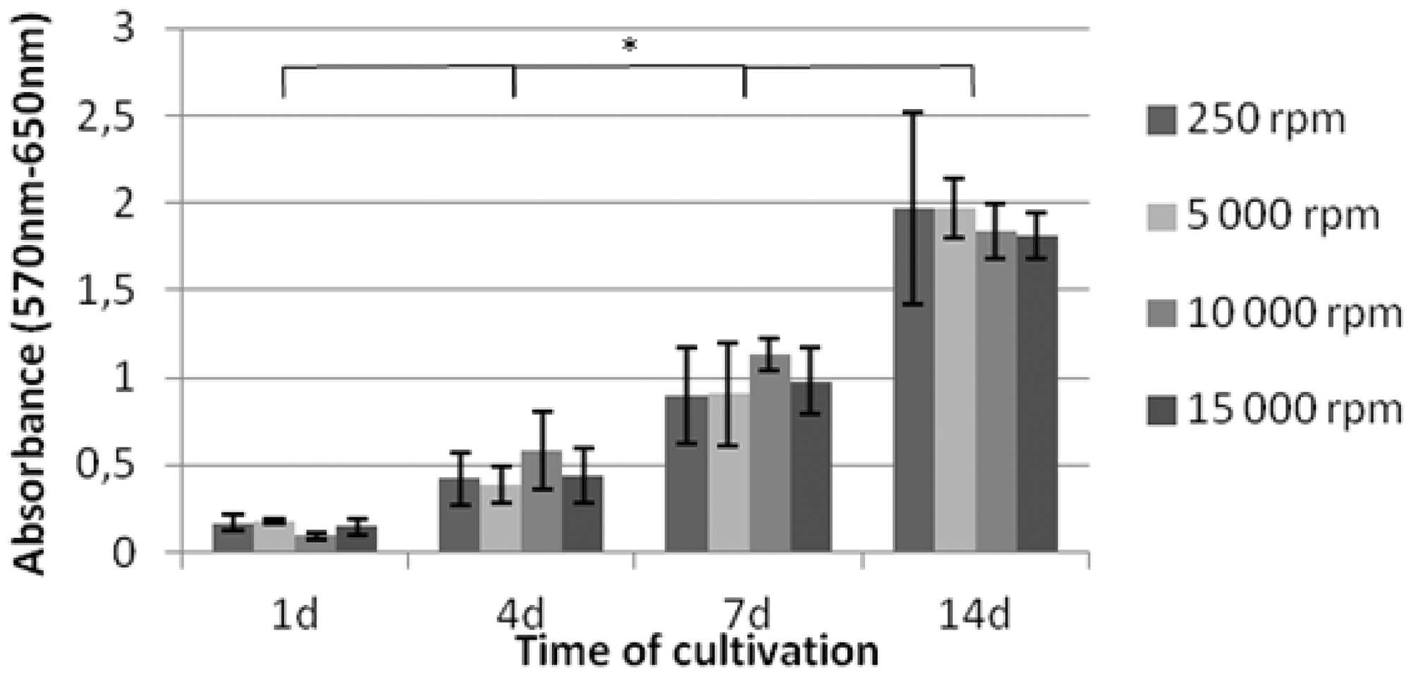
Fluorescence microscopy
The fluorescence microscopy results confirm the results of the MTT test. Conversely, it is clear from the microscopic pictures that cells became oriented in the same direction as fibers in the oriented samples obtained at 5000, 10,000, and 15,000 r/min (Figure 8). To evaluate cell elongation, the ratio of maximum and minimum cell nuclei diameter was calculated. The results are summarized in Table 2. In the nonoriented fiber samples obtained at 250 r/min, the measured ratio is 1.22. In the oriented fiber samples, the ratios are increased with increasing rotational speed (1.75 at 5000 r/min, 1.87 at 10,000 r/min, and 1.94 at 15,000 r/min) which indicates that cells are also oriented in the direction of the fiber alignments (Figure 8). Image J test results show similar trend as described by manual measurement. In nonoriented structure (250 r/min) the cell nuclei had the smallest AR (1.26 ± 0.19) and the highest degree of circularity (0.76 ± 0.11) compared to oriented structures (AR in range of 1.52–1.69 and circularity in range of 0.57–0.66). Although no significant differences were achieved among oriented samples of both measurements, nonoriented fiber samples were statistically different from oriented fiber samples regarding to cell elongation (P < 0.05).
Fluorescence microscopy pictures of 3T3 mouse fibroblasts nuclei stained with propidium iodide after 1 day of culturing isotropic structure (250 r/min) (a), and anisotropic structure (15,000 r/min) (b). Scale bars 25 µm. Summary of cell nuclei elongation (means ± SD of cell elongation ratio, aspect ratio, circularity).

SEM
From the SEM images, it can be seen how cells spread across the PCL fibrous layer (Figure 9). In the anisotropic structures, the cells become oriented as was confirmed by fluorescence microscopy. In the isotropic structures, the cells are randomly distributed.
SEM pictures of isotropic structure (250 r/min) with 3T3 mouse fibroblasts after 7 days of culturing (a) and anisotropic structure (15,000 r/min) after 7 days of cell culture (b). Scale bars 50 µm.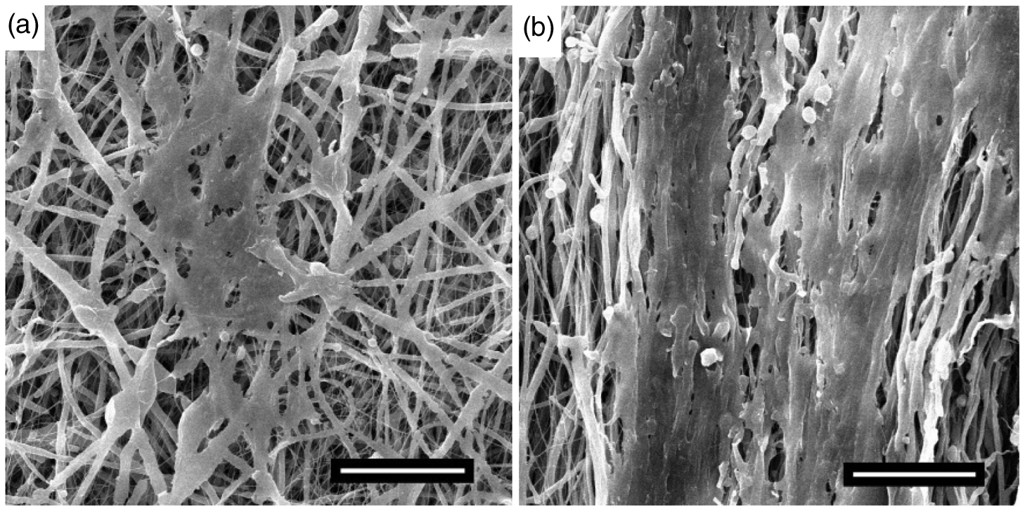
Discussion
To study structure of blood vessel, histological analysis of native artery was carried out. Microscopic images (Figure 2) reveal ECs are arranged through a single layer covering the luminal surface, whereas SMCs are organized into numerous layers inside the tunica media. From the structural proteins, elastin, which gives elasticity of the vessel, was found densely in the lamina elastica interna, as well as the tunica media and the tunica adventitia. Our results have already been mentioned in the literature [13–15,18–20]. It was also observed that fibrous collagen bundles oriented in a radial manner appear in micrometer scales (Figure 2(b)). The electrospinning apparatus (Figure 1) was adjusted in order to produce the tubular scaffolds with the desired structural properties. Because of the pliable nature of PCL, the detachment of the tubular scaffold was possible [14]. Fibrous layers were produced in range of fiber diameters approximately 2 µm similar to that of ECM fibers such as collagen bundles as documented by the SEM images (Figure 2(b)). The use of microfibers instead of nanofibers for improved SMCs viability and promoted cell colonization was confirmed by Gaudio et al. [25]. The wall thickness of analyzed native artery varied from 400 to 1000 µm along its length. Scaffolds produced by electrospinning for 90 min resulted in graft wall thickness of around 250 µm. The idea is to produce multilayer structure that will facilitate ingrowth of ECs as well as SMCs that are critical for maintaining all blood vessel physiological functions. In the light of the histological analysis of native vessel and literary survey, fiber orientation was studied as one of the crucial parameters in designing vascular scaffolds, i.e. the tunica media. In order to investigate fiber orientation in the radial direction, the rotational speed of the collector was varied from 250 to 15,000 r/min. Oriented electrospun fibers were achieved at 5000 r/min (94.2 m/min) and 10,000 r/min (188 m/min) by using a 6 mm diameter mandrel type collector. The prevailing fiber orientation in the radial direction was improved with the increasing rotational speed up to 15,000 r/min (282.6 m/min). In order to obtain radial fiber orientation, linear velocities were found in the range of previously confirmed values (200 m/min) by Hu et al. [30] and 150 m/min by Edward et al. [22]. There is no fiber orientation observed at 250 r/min (4.71 m/min) since fibers are not exposed to a notable extension force less than 120 m/min speed [22]. Pore size area and porosity are other important parameters for cell infiltration through the vascular grafts’ layers. Based on the findings of the histological analysis, it is observed that SMCs are present in the tunica media (Figure 2(a)). To enable SMCs growth into the structure, pore sizes have to be sufficient. Ju et al. suggest that pore sizes higher than 10 µm (for circular pore estimation it corresponds to more than 78.5 µm2) would permit adequate cellular infiltration [4]. Therefore, oriented layers with higher pore size area could enable cell growth into the multilayer structure. This is another reason why oriented layers seemed to be more appropriate for the tunica media. The results for the lowest pore size areas at 250 r/min sample are joint results of two analysis techniques. However, when the values are compared, some differences can be noted between the pore size areas and porosities. This can be explained by the difference in the measuring principles of the Bubble method mentioned earlier. For the oriented samples in particular, it is noticeable that there are less interconnecting fibers that can bind the sample together against the air pressure during the test. Therefore, the samples extend more during airflow which results in bigger pore size. Mechanical performance tests of the scaffolds were carried out. Tensile strength of the scaffolds at 250 r/min was found in the range of 0.35–0.5 MPa which shows no significant difference with direction (P < 0.05). On the other hand, tensile strength of the scaffold in the radial direction was improved (around 1 MPa) by obtaining radial fiber orientation. However, it caused a distinct drop in its elongation at break (50–70%). The results show a common mechanical behavior of fibrous structures. Vascular grafts are exposed to four forces (i) shear stress, (ii) luminal pressure (a cyclic normal force attributable to blood pressure), (iii) mechanical stretch (a cyclic circumferential stress caused by blood pressure), and (iv) tension in longitudinal direction as described via Isenberg et al. [3] Although radial tensile strength is improved by the resulting fiber orientation, its elasticity, i.e. the elongation at break, decreased in the radial direction. In a study of Ju et al. [4] 0.71 MPa tensile strength was achieved for PCL–collagen (1:1) in Hexafluoroisopropanol (HFIP) solution (2.39 µm fiber diameter) whereas 1.2 MPa tensile strength for PCL–chloroform solution (fiber diameters in the range of 1.5–6 µm) was achieved by Vaz et al. [14] regardless of direction. Tensile strength of natural abdominal aorta was stated as 1.47 MPa in longitudinal and 5.49 MPa in radial direction by He et al. [35] which prove radially oriented fibrous collagen bundles in the structure. Although mechanical test results of this study match with literature, it must be improved to meet the requirements of native vessels. Therefore, design of a multilayer structure seems to be appropriate to mimic mechanical as well as morphological properties of native vessel. Biocompatibility of PCL fibers was evaluated using mouse 3T3 fibroblasts. Cell alignment and viability was measured. MTT assay showed no significant difference in cell numbers between samples of various planar anisotropies during 14 days of culturing. However, elongated cell shapes were observed which suggests that cells tend to orient themselves with the fibers in the radial direction. The increase in nuclei elongation ratio, which were calculated as 1.22, 1.75, 1.87, 1.94 for 250, 5000, 10,000, and 15,000 r/min, confirmed cell orientation along the fibers. Since all these mechanisms contribute to normal cell behavior, specialized cell types (ECs and SMCs) need to be tested in a dynamic bioreactor cultivation system [35] to provide more realistic simulations.
Conclusion
This study provides a new perspective for designing small-diameter vascular grafts. Based on the hypothesis of tissue engineering, mimicking cellular environment of natural tissue is beneficial for cell infiltration. Therefore, an understanding of the structure and properties of the target tissue has to be attained. With this in mind, histological and morphological analyses of the native blood vessel were carried out, the results of which provided an insight into designing vascular grafts. Cell organizations as well as structural proteins were observed to enlighten our design parameters for vascular grafts. Tubular scaffolds used as vascular grafts were produced under optimized conditions by a custom-designed electrospinning apparatus. Fiber orientation was obtained by increasing the rotational speed of the collector and besides mechanical performance structural properties mainly, fiber orientation, pore sizes, and porosity were investigated in order to test its adequacies for cell attachment and cell diffusion ability. Biocompatibility of PCL was found sufficient by MTT test using 3T3 fibroblasts, while morphological analysis of seeded samples under fluorescence microscope and SEM confirms that cells are aligned along the fibers. Although many design parameters were successfully examined in this study, future attempts should mainly be directed at: (i) design of a multilayer scaffold to mimic native vessel, (ii) improving the radial elasticity, and (iii) seeding the graft with specialized cell types using dynamic cultivation.
Footnotes
Acknowledgement
The authors are thankful to Ondrej Novak, Department of Nonwovens and Nanofibrous Materials, Technical University of Liberec for providing material’s mechanical characterization and to Jakub Hruza, Department of Nanotechnology and Informatics, Technical University of Liberec for providing the Bubble method testing apparatus. D.L. acknowledges the support of GACR, Grant no. P208/12/0105.
Declaration of Conflicting Interests
The author(s) declared no potential conflicts of interest with respect to the research, authorship, and/or publication of this article.
Funding
The author(s) received no financial support for the research, authorship, and/or publication of this article.