
Abstract
Carbon nanotubes are among the stiffest and strongest fibres known and they are thus considered as ideal fillers for polymeric fibre reinforcement. Carbon nanotube polymer composites have consequently attracted huge academic and industrial interest with thousands of relevant research works being published every year. In current work, we present a quite integrated study of multiwall carbon nanotube (MWCNT)-reinforced poly ethylene terephthalate (PET) composites prepared at laboratory scale along with industrial melt-spun fibres. For an optimum dispersion of the nanomaterial in the polymer matrix, we proceeded to appropriate functionalization of multiwall carbon nanotubes. The morphology of the composites was inspected by scanning electron microscope and transmission electron microscope, while the physical properties, such as crystallinity and orientation, by differential scanning calorimetry, X-ray diffraction and Raman spectroscopy. The addition of well-dispersed carbon nanotubes acts as a nucleation agent increasing the crystallization of poly ethylene terephthalate matrix, however, decreasing the orientation of either films or fibres. Carbon nanotubes /poly ethylene terephthalate polymer composite films present an increment of Young’s modulus and tensile strength to detriment of failure strain; namely, stiffness is accompanied by a less ductile behaviour. With the addition of carbon nanotubes to poly ethylene terephthalate fibres, a decrease in shrinkage and only a slight improvement in dimensional stability was attained; this once more explains the slow growth of their commercial applications since the mechanical properties of these materials still remain a fraction of the expected theoretical values.
Keywords
Introduction
Until the end of the 19th century only natural fibres, such as cotton, wool and silk, were available. In 20th century, with the birth of polymer science, synthetic fibres have been developed, such as polyesteric, polyacrylic and polyolefinic. One of the innovative technologies in recent years aimed at improving the mechanical properties of materials by reinforcing using fillers. The end-product application is a key factor to be considered in the fibre manufacturing processes, since fibres can be conceived to be converted to either conventional textile fibres or to high-performance fibres with high mechanical properties for explicit uses. Recently, emphasis is given on protecting people from occupational and recreational hazards. As a consequence, new textile fibres and clothing design and concepts are adopted to provide improved protection, maintaining comfort, efficiency and well-being. In this context, we resorted to the support of nanotechnology already being applied in engineering. Nanotechnology is the term given to those areas of science and engineering where phenomena that take place at dimensions in the nanometre scale are utilised in the design, characterisation, production and application of materials, structures, devices and systems [1]. Nanomaterials in turn, which we expect to supply with a commonly accepted definition [2], may completely present different properties from normal materials.
Carbon nanotubes (CNTs) constitute a particular expression of nanotechnology and nanomaterials being among the stiffest and strongest nanofibres known. Since Iijima’s relevant report in 1991 [3], CNTs have attracted great attention in the manufacturing of polymer nanocomposites being considered as ideal fillers for polymeric fibre reinforcement. Moreover, their exceptional electronic, optical and chemical properties [4,5] make them attractive for many applications with numerous of relevant research works being published every year.
The morphology of a CNT is defined by the orientation and magnitude of the chiral vector in a graphene sheet, which is ‘wrapped-up’ to form the single-walled carbon nanotube (SWCNT). A note is made of the fact that SWCNTs with one or more external dimensions below 1 nm should be considered as nanomaterials [1,2]. The density of SWCNT, elastic modulus and tensile strength are found to be 1.33–1.40 g/cm3, 1.2 TPa and 2 GPa, respectively [6]. Their morphology depends on the nanotube length, diameter, chirality and the tube-end configuration (end-caps). The morphology of multi-walled carbon nanotubes (MWCNTs), composed of nested SWCNTs, depends on nanotube outer and inner diameter, number of nested SWCNTs (wall thickness) and growth-induced configuration [7]. Since CNTs usually agglomerate due to Van der Waals forces, it is extremely difficult to disperse and align them in a polymer matrix. The defect functionalization, covalent or non-covalent, of CNT is an effective way to prevent nanotube aggregation, which helps to better disperse and stabilize them within a macromolecular microstructure. In covalent functionalization, usually, functional groups such as carboxyls (–COOH) or hydroxyls (–OH) are created on the CNTs by oxidation via O2, concentrated sulphuric acid, nitric acid, aqueous hydrogen peroxide and acid mixture [5,8–10]. Additionally, polymer grafting is particularly important and efficient via amidation, esterification and radical coupling [11]. Polymer composite is the biggest application area for CNTs. The excellent mechanical properties of CNTs suggest that incorporation of very small amount of CNTs into a polymer matrix can lead to structural materials with significantly high modulus and strength. Improvement in tensile modulus and strength, hardness as well as indentation resistance were reported in the literature [12–15]. However, the extraordinary properties of CNTs are still not fully utilized/exploited in polymer composites.
High performance CNT/poly ethylene terephthalate (PET) polymer composites have been fabricated in bulk state such as thick films [16–18]; however, CNT/PET composite fibres with improved mechanical properties have been only scarcely reported and specifically for the case of SWCNT [19,20]. This may indicate that it is difficult to control relevant fibre structure due to the type/degree of CNT dispersion in the matrix and the CNT orientation along the development direction of the fibres. The mechanical properties of polymer CNT composite fibres are anticipated to be highly dependent on CNT dispersion and orientation as well as to polymer crystallinity and macromolecular orientation. An essential processing issue is the homogeneous dispersion of debundled CNTs in the polymer matrix; this is crucial to fully utilize their exceptional properties. The addition of CNTs in polymeric fibres has been shown to affect their physical structures, enhance tensile properties, reduce fibre shrinkage, improve chemical resistance, increase electrical and thermal conductivities and lead to higher polymer thermal transition temperatures [21]. Melt-spun composite fibres showed poorer mechanical properties than net PET, even in the case of relatively well-dispersed functionalized CNTs; however, the tensile strength of annealed composite fibres was found higher than the corresponding of annealed pure PET fibres, while the modulus was improved [22].
In the present study, lab-scale preparation and up-scale spinning fibre processing of MWCNT/poly(ethylene terephthalate) composites were accomplished. Chemical functionalization, via oxidation, of MWCNT was primarily performed for better CNT dispersion in polymer matrix. A variety of melt-mixed MWCNT/PET compositions prepared in laboratory were studied for their mechanical and physical properties. MWCNT/PET master batches and relevant extruded, melt-spun and drawn fibres were developed and subsequently characterized and compared.
Material and methods
Materials
PET was provided by INVISTA Resin & Fibres (Germany). High purity MWCNT, 97%, were purchased from Nanothinx S.A. (Greece). More specifically, the CNT product (NTX1 Nanothinx) with outside diameter of 15–35 nm and a length ≥10 µm was produced using the catalytic chemical vapour deposition method (CCVD), of hydrocarbon sources on substrates of metal oxides impregnated with metal catalysts (Fe and Al). The CVD method is known to produce batches that are generally free from amorphous carbon and carbon nanoparticles [23,24]. Carboxyl (–COOH) functionalized MWCNTs (NTX5) were also obtained from Nanothinx. Sulphuric acid (98% v/v), nitric acid (68% v/v) as well as hydrogen peroxide (30% v/v) were purchased from Sigma Aldrich (Germany).
Oxidation of MWCNTs
Beyond the use of the Nanothinx carboxyl functionalized MWCNTs (NTX5), we proceeded to the chemical oxidation of the pristine NTX1 type CNTs. Two different acid treatments (A & B) were used for the introduction of carboxylic groups onto MWCNTs. Briefly, for the A treatment, 0.3 mg of the NTX1 type CNTs were oxidized with 25 mL HNO3 under stirring for 15 min followed by sonication for 2 h. After profound washing of the CNTs with distilled water, the same procedure was followed this time with hydrogen peroxide [25]. For the B oxidation method, 0.3 mg of as received NTX1 CNTs were sonicated for 10 min in a mixture of 25 mL HNO3 and 25 mL H2SO4 and afterwards refluxed at 140℃ for 1 h and finally washed with triple distilled water. MWCNTs oxidized by both methods were lastly dried in an oven at 60℃ for two days and the samples were labelled as MWCNT-A and MWCNT-B, respectively.
Preparation of CNT/PET composites and fibres
MWCNT/PET composites at laboratory level were fabricated by melt blending in a home-made batch-mixer which consists of a stainless steel vessel equipped with a piston, where working temperature (up to 500℃) and screw speed (12–46 r/min) can be easily selected. When working at high temperature, N2 is directly diffused from the top into the sample vessel to avoid polymer oxidation at higher temperature. For the MWCNT/PET blends the temperature of the mixer was set at 270℃. Composites of varying MWCNT weight content, of 0.5%, 1% and 2%, were obtained. Polymer films were prepared by melt pressing a small part of the master batch at 290℃ and 30 bar followed by quenching in ice water; low crystallinity films were thus obtained. After film preparation, dog-bone-shaped samples were cut for tensile measurements. Film thickness was about 150 µm.
For the scale up production of MWCNT/PET composite fibres (monofilament), firstly the required amount of functionalized CNTs either by A or B treatment, were prepared. Neat PET and PET blended with functionalized MWCNT were extruded in a Leistritz ZSE 67 GG industrial extruder (at Souris & Co SA Color for Plastics premises). This extrusion process was adopted for the dispersion of CNTs in the polymer matrix.
The polymer composite chips thus obtained were subsequently solid state polymerized (at Kordsa Global premises) at a temperature above 200℃ for 18 h under nitrogen atmosphere in order to increase the intrinsic viscosity (≥1.1 dL/g) and relevant molecular weight; during this process, samples were regularly taken out and their intrinsic viscosity was checked. Prior to fibre spinning and drawing, all polymer composite chips thus obtained were oven dried at 140℃ overnight under continuous vacuum to reach less than 0.006% (60 ppm) humidity. In the extrusion of the spinning process, a single screw with a mixing part was preferred. During the entire spinning processes, a spinneret with L = 5 mm and D = 1 mm was used. The melt was quenched below glass transition temperature (Tquench = 65℃ being the Tg measured 78℃) in a water bath. In the spin line (between the spinneret and take-up roll) the draw ratio was kept at 5.1; in the draw line (between the take-up and the last heated roll) the draw ratio was changed from 4.9 to 5.6, while heating above both the glass transition (Tg) and the cold crystallization temperature (Tcc) and just below crystallization temperature (Tc) through the line. The most reproducible and repeatable data were obtained at the draw ratio of 5.3.
Measurements
Thermogravimetric analysis (TGA) studies were performed on a TGA Q50 (TA instruments) under nitrogen atmosphere at 10℃/min and at a temperature range from 30℃ to 800℃. Morphological analysis of functionalized MWCNTs was achieved by both scanning and transmission electron microscope, SEM and TEM, images. A Zeiss SUPRA 35VP model was used for the SEM images obtained. Quite dilute concentrations of the CNTs in water were bath sonicated for 2 min and a drop was spread on Si surfaces and allowed to dry prior to SEM measurements to avoid bundles formation of CNT. TEM images were obtained on a JEOL JEM2100 operating at 200 kV. Sample preparation for TEM examination involved the ultrasonic dispersion of the sample in water and a drop of the suspension was placed on 3 mm carbon-coated cooper grid. SEM images were also performed on films and fibres. Differential scanning calorimetric (DSC) measurements on MWCNT/PET composite films and fibres were carried out using a TA instruments Q100 thermal analyzer at a heating rate of 10℃/min. In addition to DSC, in order to further characterize the crystalline structure of the fibres, XRD analysis was performed with a diffractometer (Bruker D8 Advance) using Cu Kα radiation (λ = 0.15418 nm). The measurements were carried out in the 2θ angle range of 10–90°. Polarized Raman spectra were also collected to evaluate the molecular orientation of the composite fibres and films [26]. Raman spectra were mainly recorded using a modified custom made Dilor Super Head of Jobin Yvon (F)–Horiba (J). The Raman spectra were excited with the linearly polarized light of a solid state Nd:YAG laser, doubled frequency at 532 nm, attached to the Raman micro-head. The collected backscattered light was launched onto the core of an optical fibre after being passed through a notch filter. Polarization measurements were performed by using a motorized half wave plate able to select the polarization direction on the excitation laser beam while an also motorized analyzer permitted the selection of one component on the scattered beam.
Lastly, mechanical properties of PET nanocomposites films were measured with an Instrom Model 3344 Universal Testing System, according to the procedures of the ASTM D 638 standard. The gauge length and the crosshead speed were set to 10 mm and 10 mm/min, respectively; values provided in this study are an average of five measurements.
For fibres, a Universal Testing Machine (INSTRON Model 5965) and procedure according to ASTM D885 were used for the stress–strain measurement with the load cells depending on the strength of fibre; elongation speed was 304.8 mm/min. The total distance between the clamps were 150 mm and the specimen length was 48 mm. Breaking strength (BS) and elongation at break (EB) were directly obtained and expressed in ‘kgf’ and ‘%’ respectively, averaged over 10 measurements. Tenacity was calculated dividing BS with the denier of the yarn (dtex x 0.9) and given in terms of ‘gpd’, grams per denier. Elastic modulus was calculated from the linear portion of the stress–strain curve and for fibre diameter the unit was GPa. A hot air shrinkage machine was used for relevant measurements. The specimen length was 50 cm; however, only the half of it was subjected to heat. The load was varied depending on the fibre weight dtex (load = dtex x 0.045). The measurement temperature and time were 177℃ and two min, respectively. Dimensional stability ratio (DSR) was calculated by adding elongation at specific load (EASL) at 0.5 kgf (5 N) and shrinkage values. The lower is the DSR value the better is the dimensional stability; which is the ability of a material to maintain its essential or original dimensions while being used for its intended purpose
Results and discussion
Characterization and dispersion of MWCNTs
TGA was the first analytical technique used for the evaluation of the degree of oxidation achieved on the acid treatments applied on the MWCNTs. The weight loss curves of raw MWCNT (NTX1) and functionalized MWCNTs are represented in Figure 1. TGA were conducted under nitrogen atmosphere. The weight losses of the as received MWCNTs, NTX1, were only 3% after being heated to 700℃, indicating a well-graphitized structure; a note is made of the fact that disordered or amorphous carbons tend to lose weight at around 500℃. For NTX5, the weight loss is 4%, while the corresponding functionalized MWCNTs by the A and B acid treatment modes indicate a successful degree of functionalization of 8% and 15%, respectively.
Thermogravimetric analysis (TGA) thermograms of multiwall carbon nanotubes (MWCNTs): (a) pristine MWCNTs (NTX1), (b) NTX5, (c) MWCNTs-HNO3/H2O2− (A) and (d) MWCNTs-HNO3/H2SO4−(B).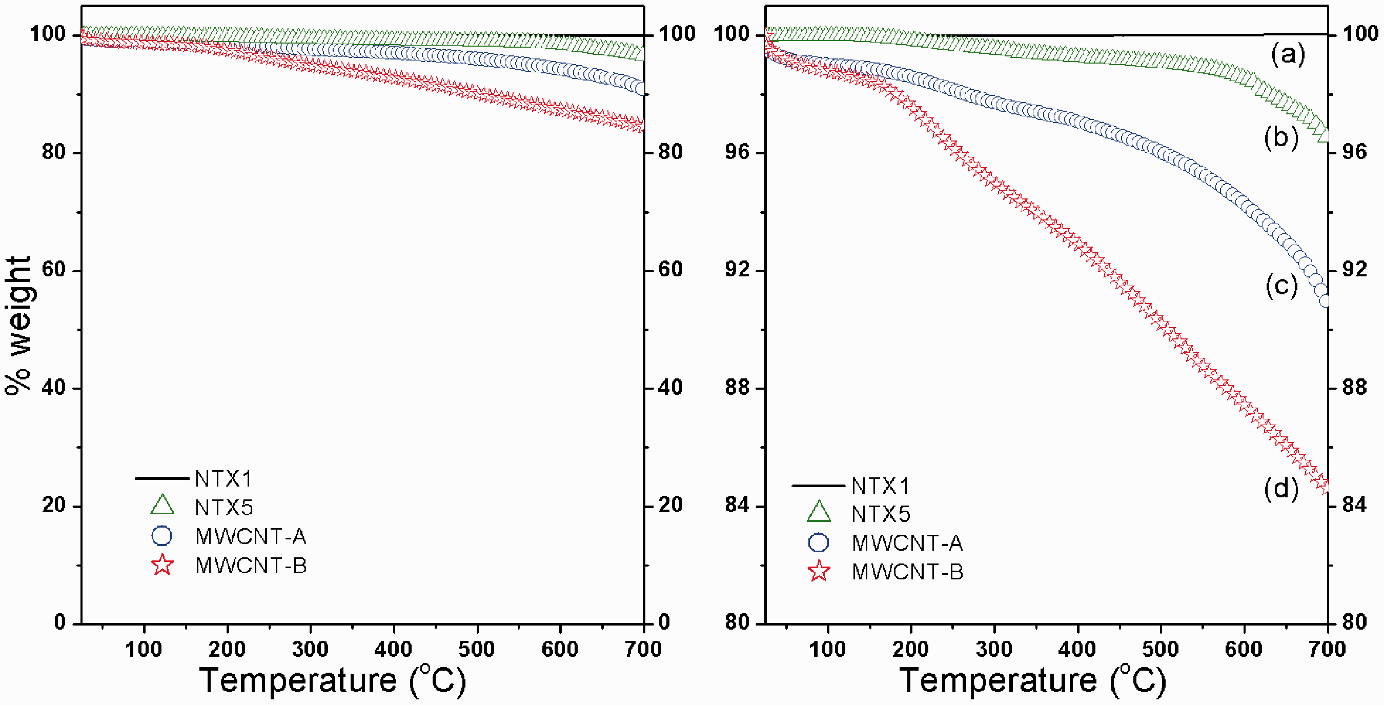
Functionalized MWCNTs were further characterized by X-ray photoelectron spectroscopy (XPS). The photoemission experiments were carried out in an ultra-high vacuum system (UHV) which consists of a fast entry specimen assembly, a sample preparation and an analysis chamber. The base pressure in both chambers was 1 × 10⁻⁹ mbar. Unmonochromatized MgKα line at 1253.6 eV and an analyser pass energy of 36 eV, giving a full width at half maximum (FWHM) of 0.9 eV for the Au 4f7/2 peak, were used in all XPS measurements. The XPS core level spectra were analysed using a fitting routine, which can decompose each spectrum into individual mixed Gaussian-Lorentzian peaks after a Shirley background subtraction. The samples were pressed into pellets. The calibration of the analyzer’s kinetic energy scale was done according to ASTM-E 902-88. Errors in our quantitative data are found in the range of ∼10% (peak areas), while the accuracy for BEs assignments is ∼0.1 eV. The XPS scans show the elements present on the CNTs surfaces, carbon and oxygen were detected both in the pristine NTX1 and in the acid-treated samples. Deconvolution of the C1s peak of the pristine NTX1 CNTs (not shown here) presented a main peak at 284.5 eV attributed to the graphitic structure. Moreover a peak at 285.5 eV was attributed to defects on the nanotube structure, whereas peaks correspond to carbon atoms attached to different oxygen-containing moieties appear at 286.6 eV (carbon singly bound to oxygen in phenols and ethers), 288.3 eV (carbon double bond to oxygen in ketones and quinones), 289.3 eV (carbon doubly bond to two oxygen in carboxyls, carboxylic anhydrides and esters) and aromatic compounds at 291.2 eV (π–π* transition) [10,27]. It is evident an increase of oxygen content on the walls of MWCNTs after acid treatment, being the MWCNTs treated with a mixture of acids (treatment B) the ones with the higher amount of oxygen.
Relative content of functional groups, % sp2, % sp3 from XPS C1s spectrum deconvolution together with % atomic oxygen and carbon.

MWCNT: multiwall carbon nanotube; NTX: nanothinx carboxyl functionalized MWCNTs; XPS: X-ray diffraction.
SEM and TEM have been used to perceive probable morphological changes of MWCNTs depending on the applied acid treatment. After oxidation, fragmentation of the CNTs takes place with a new average length estimated at 3–4 µm compared to ∼10 µm of the pristine ones. It should, however, be noted here that longish CNTs are important in composites for the stress transfer between polymer matrix and CNT. Representative SEM and TEM images of MWCNT-A samples obtained by HNO3/H2O2 treatment are shown in Figure 2.
Scanning electron microscope (SEM) (left) and transmission electron microscope (TEM) (right) images of multiwall carbon nanotube (MWCNT)-A.
The dispersion of CNTs in the polymer matrix can be observed in Figure 3 where SEM images of cryogenically fractured MWCNT/PET films are shown. An appropriate dispersion of CNTs in the polymer matrix is an important parameter to fully utilize the exceptional properties of CNTs and for monitoring thermal and mechanical properties of the final composite material. A poorly dispersed composite is observed for pristine MWCNT (NTX1) and specifically for MWCNT-B. When MWCNTs tend to aggregate forming bundles (indicated by arrows in Figure 3), there is low uniform distribution and in consequence low interfacial adhesion between the polymer and CNTs. The best dispersion of CNTs in the polymer composite was achieved using MWCNT-A type, a more uniform dispersion of CNTs is seen in the central SEM images compared with bundles observed for images on the right image.
Scanning electron microscope (SEM) images of fracture nanocomposites containing 1% in carbon nanotubes (CNTs): PET/NTX5 on left, PET/ MWCNT-A treatment on centre and PET/MWCNT-B treatment on right. MWCNT: multiwall CNT; NTX5: nanothinx carboxyl functionalized MWCNT; PET: poly ethylene terephthalate.
Crystallization characterization
Thermal properties of MWCNT/PET composite films based on DSC results.

DSC: differential scanning calorimetry; MWCNT: multiwall carbon nanotube; NTX: nanothinx carboxyl functionalized MWCNTs; PET: poly ethylene terephthalate.
Crystallization characteristics revealed from DSC measurements for laboratory films and industrial monofilament fibres build up from PET composites incorporating CNTs modified/oxidized by the A treatment type are depicted in Figure 4. The cold crystallization temperature of film appears at 121℃ but is absent for the fibre; this indicates that the polymer chains in the fibre are well crystallized during fibre spinning and no further crystallization occurs during DSC thermograph as for the film case. The melting temperature for both film and fibres appears near 255℃, with the peak of the fibre being sharper, indicating again a well-oriented induced crystallization with a narrow crystallite size distribution bearing more ordered and perfected crystallites. Significant increase from 13 to 37% in the crystallinity values from the film to the fibre was respectively observed and was attributed to the orientation-induced crystallization in melt spinning of the MWCNT/PET composites.
DSC curves for MWCNT-A 1%/PET composites obtained for a lab-scale film and an industrial melt-spun fibre. MWCNT: multiwall carbon nanotube; PET: poly ethylene terephthalate.
Mechanical properties
Effect of MWCNT loading on mechanical properties of neat PET and PET composite films at 0.5 wt%, 1 wt% and 2 wt% MWCNT loading.
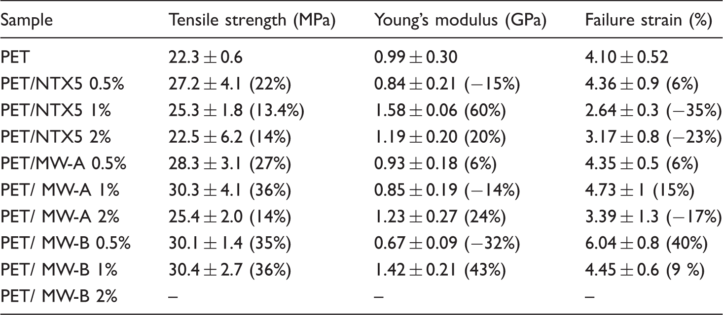
MWCNT: multiwall carbon nanotube; NTX: nanothinx carboxyl functionalized MWCNTs; PET: poly ethylene terephthalate.
Mechanical properties of neat PET and PET/ MWCNT-A 1% composite fibres performed at MDR = 5.3 and DDR = 5.1.

BS: breaking strength; DDR: draw down ratio; EB: elongation at break; MDR: machine draw ratio; MWCNT: multiwall carbon nanotube; PET: poly ethylene terephthalate.
Grams per denier.
The absence of significant improvements in the mechanical properties when comparing MWCNT-reinforced PET polymer composites with pure polymer films and the fact that melt-spun and drawn composite fibres showed slightly reduced mechanical properties than pure PET seem to agree with relevant findings pointed out by other studies dealing also with MWCNT/PET composites [8,16,18]. The lower EB can be explained by entanglement formation between CNTs and polymer matrix, which might disturb the orientation of CNTs (see below). Enhanced tenacity and modulus accompanied, however, by a reduction of elongation for PET fibres have been reported for the case of reinforcement with SWNTs [19,21]; it is also stated there that both tenacity and modulus values of the fibres were increased with draw ratio due to molecular orientation and crystallization induced by drawing. Enhanced tenacity and modulus have been reported for PET composites containing MWCNTs only when annealing of melt spun MWCNT/PET fibres occurred [8].
Molecular orientation
It is well known that the achievement of molecular orientation in polymers leads to a significant improvement of their properties and especially in fibres along their drawn axis. At lab-scale, dumbbell-shaped test strips with a narrow mid-section of 6.5 mm width were cut from the MWCNT/PET composite films prepared by melt pressing and stretched in a home-made stretching element [26]. For these samples the stretching temperature was 85℃ (10℃ above the Tg) and the draw ratio, λ, was calculated as the ratio of the extended length to the original length. In Figure 5, typical polarized Raman spectra of a representative PET film before and after uniaxial drawing are depicted, using two polarization geometries. The 1616 cm−1 peak in PET corresponds to the symmetric stretch of the 1,4 para substituted benzene ring. Before drawing, there is no preferred orientation since the sample is essentially isotropic at a molecular level; thus no differences are found between VV and HH scattering intensities for all spectral features. However, when the sample is stretched, e.g. up to a draw ratio λ = 4, the VV and HH spectra develop differences in relative band intensities. The extent of such differences depends on the position of the sample, v-vertical, with respect to the laboratory-fixed coordinates, and reflects the anisotropy induced by the drawing process. For the drawn sample, the scattering intensities of the skeletal vibrational modes are higher in parallel to the draw direction polarization geometries, v-VV, than in the corresponding cross polarization geometries, v-HH. That means there are more scatterers of para-di-substituted benzene rings in the v-VV geometries, more benzene rings aligned towards the draw direction, more macromolecular chains parallel to the draw direction.
Polarized Raman spectra of poly ethylene terephthalate (PET) film undrawn (λ = 1) and drawn to λ = 4 in two different polarization geometries, VV and HH, with respect to the position of the specimen relative to the laboratory-fixed coordinates, v. The spectra are shifted along the intensity axis for clarity.
Similar behaviour is found for uniaxially drawn MWCNT-A 1% /PET and MWCNT-B 0.5% /PET samples via the corresponding polarized Raman spectra depicted in Figure 6. The characteristics peaks related to CNTs can be also observed in the composite containing MWCNT-A 1%; they are marked by arrows at 1575 cm−1 (G band) and 1350 cm−1 (D band) [28–30]. A certain degree of molecular orientation is observed for the stretched MWCNT-A1% /PET film, although less than the respective is achieved in the case of PET (Figure 5) and MWCNT-B 0.5% /PET samples; they both exhibit higher polarization ratio (Iv-VV/Iv-HH) for the 1616 cm−1 Raman peak at the same λ = 4. When CNTs are well dispersed in PET (as is the case of MWCNT-A1% /PET film samples), they disturb the chain mobility of the polymer macromolecular chains preventing them to achieve high degrees of molecular orientation upon drawing. The stiffness of the polymer matrix has increased by the addition of CNTs as has been revealed by the stress–strain measurements above. It seems that macromolecular chains are somehow trapped/immobilized and they cannot be stretched as freely as compared with PET and MWCNT-B 0.5% /PET samples. An interesting outcome from the polarized Raman spectra is that the addition of well dispersed CNTs prevents by some means the orientation of the polymer macromolecular chains.
Polarized Raman spectra of MWCNT/PET films undrawn (λ = 1) and drawn to λ = 4 in two different polarization geometries, VV and HH, with respect to the position of the specimen relative to the laboratory-fixed coordinates, v. Left: PET composites bearing MWCNTs-A 1%. Right: PET composites bearing MWCNTs-B 0.5%. MWCNT: multiwall carbon nanotube; PET: poly ethylene terephthalate.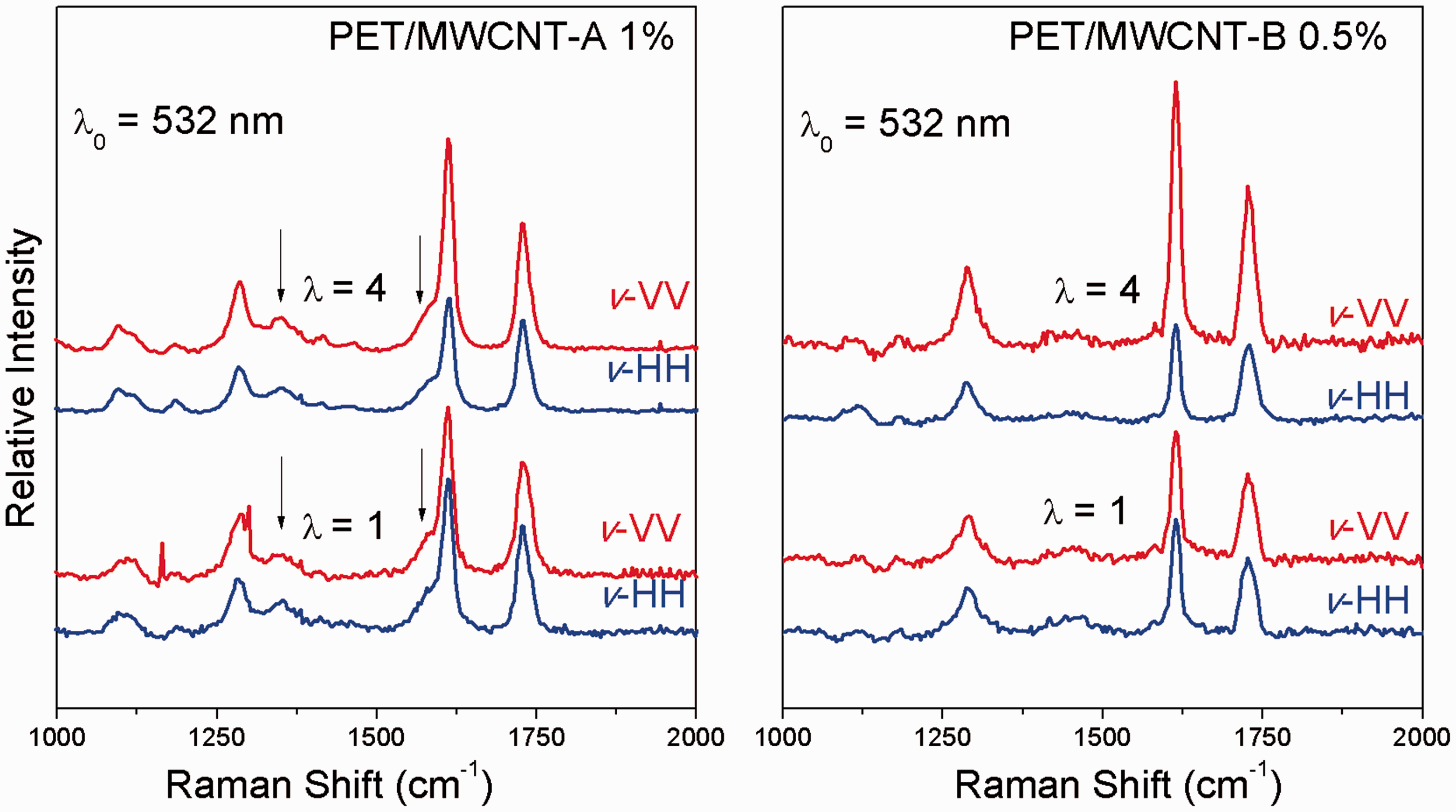
Similar to the above results are found for the macromolecular orientation in PET and MWCNT-A 1% /PET fibres depicted in Figure 7. During the spinning process, pure PET fibres exhibit higher polarization ratios, or in other words enhanced molecular orientation in the drawing direction than MWCNT/PET composite fibres. Analogous outcomes have been reported in similar studies [31], explaining that modification of flow conditions are developed around the nanoparticles added to the polymer matrix. The applied elongation field on the pure polymer phase is reduced by converting a fraction of the elongation flow into a shear component at the CNT/polymer interphase. This reduction in the strength of the elongational flow imposed on the polymer melt could explain the restriction of the overall degree of orientation in CNTs nanocomposites compared to the pure PET fibres. Finally, the measured mechanical properties of these PET/CNTs nanocomposites still remain a fraction of the expected theoretical values [32].
Polarized Raman spectra of net PET and MWCNT-A1% /PET fibres drawn to λ = 4 in two different polarization geometries, VV and HH, with respect to the position of the specimen relative to the laboratory-fixed coordinates, v. MWCNT: multiwall carbon nanotube; PET: poly ethylene terephthalate.
X-ray diffraction
The effects of the addition of CNTs to the polymer matrix on the crystallization were also studied by XRD. The PET crystal faces have been assigned [16] to the following diffraction peaks at 2θ angles: (0
In the same figure, a characteristic sharp diffraction peak for MWCNTs at scattering angle 2θ = 26.1o is attributed to the ordered arrangement of the concentric cylinders of graphitic carbon [34]. This peak appears at the same position with the (100) peak of crystalline PET. With the addition of MWCNTs to PET polymer matrix (MWCNT-A 1% /PET in Figure 8), diffraction peaks are developed at the same 2θ angles than the corresponding to PET crystalline faces assigned by Mayoral et al. [17] by the exception of the (1 X-ray diffraction (XRD) diffractogram for unfilled poly ethylene terephthalate (PET) film (bottom), multiwall carbon nanotube (MWCNT)-A 1% /PET composite film (middle) and MWCNT-A (top). X-ray diffraction (XRD) diffractogram for unfilled poly ethylene terephthalate (PET) film (left) and multiwall carbon nanotube (MWCNT)-A 1% /PET composite film (right) before stretching and stretched to draw ratio λ = 4.

Conclusions
In this work, CNTs were acid treated/functionalized and compounded with polyethylene terephthalate. MWCNT/PET composites were characterized and compared to net PET polymer at laboratory scale and so the best MWCNT/PET composites in terms of BS, elastic modulus as well as toughness were easier to be processed and were melt-spun in fibres. Based on DSC experiments, CNTs acting as nucleating agents, slightly increased the percent of crystallinity of the polymer matrix. The increased Young’s modulus presented for several composites, which measures the stiffness of a solid material and the resistance offered to deformation, was accompanied by a decrease in failure strain. Well-dispersed CNTs in the PET polymer matrix (MWCNT-A 1%/PET composite) presented increased tensile strength but reduced Young’s modulus. These findings are corroborated by molecular orientation studies using Raman spectroscopy, rigidity is enhanced when well-dispersed CNTs are incorporated into PET, CNTs disturb chain mobility and affect the elongation/relaxation of the disordered amorphous regions which bothers orientation.
Decrease in shrinkage and improvement in DSR found in MWCNT/PET fibres might indicate stiffer chains.
Footnotes
Acknowledgements
The authors would also wish to thank Dr L Sygellou for the XPS measurements and D Souris & Co SA Color for Plastics for the extrusion of MWCNT/PET composites in chips.
Declaration of Conflicting Interests
The author(s) declared no potential conflicts of interest with respect to the research, authorship, and/or publication of this article.
Funding
The author(s) disclosed receipt of the following financial support for the research, authorship, and/or publication of this article: the European Regional Development Fund (FP7/2007-2013), Western Greece Region national resources under the grant agreement no. 235527 (LEADERA – Code: 2013-006 INPROTEX) and TUBİTAK-TEYDEB (no. 9130048).