
Abstract
Multi-walled carbon nanotubes (CNTs) were functionalized on treatment with nitric acid and the surface-modified CNT was characterized using Fourier transform infrared spectroscopy (FTIR). Isotactic polypropylene (iPP)/CNT composites at different CNT loadings (i.e., 0.1, 0.25, 1.00, and 5.00 wt%) were prepared by melt blending in a mini blender. The differential scanning calorimetric (DSC) studies showed the nucleating effect of CNTs on the crystallization behavior of iPP. Results of X-ray diffraction studies are in conformity with the results of DSC studies. Results of stress–strain measurements reveal that Young's modulus increases, while elongation at break decreases with increase in CNT loading and the ductility of the composites is adversely affected at high loading of CNTs (>1.0 wt%). Functionalization of CNTs causes an improvement in Young's modulus, at all loadings studied, but elongation at break increases only up to 0.25%. At higher loading, the elongation at break drops down. Storage modulus increases with increase in CNT loading and the effect is greater in the case of functionalized CNTs. Tan δ shows a decrease with increase in CNT loading, but the effect is less pronounced at high CNT loading (>0.1 wt%).
Keywords
INTRODUCTION
Carbon nanotubes (CNTs) are fillers of recent interest in polymer matrices due to their high Young's modulus combined with good electrical and thermal conductivity. The very high aspect ratio makes it likely that the addition of a small amount of CNTs contributes to a phenomenal improvement in the electrical [1], thermal [2], and mechanical [3] properties of the polymer composites. Thus, CNT/polymer composites combine the good processability of the polymers, coupled with excellent mechanical properties of the CNTs. However, the strong intermolecular van der Waals interactions among the nanotubes, their high surface area, and high aspect ratio, cause significant particle–particle agglomeration [4]. Achieving proper dispersion of CNTs in polymer matrices is a challenge to be met while attempting to exploit the potential of polymer/CNT composites [5]. Good dispersion of CNTs has been reported in polar polymers such as poly(methyl methacrylate) [6], polycarbonate [7], polyacrylonitrile [8] and poly(vinyl alcohol) [9]. However, CNT dispersion in nonpolar polymers, such as polypropylene (PP), during melt processing remains a challenge. Techniques such as end-group functionalization [10–12], use of ionic surfactants [13], shear mixing [14,15], and plasma coating [16] have been used to improve dispersion and exfoliation of nanotubes in PP matrix.
Recent studies have shown that isotactic polypropylene (iPP) composites with single-walled nanotubes [17,18] and multi-walled [19] nanotubes have been used to study the crystallization behavior, polymer morphology, and mechanical and thermal properties, and the results have sometimes been contradictory. Ganß et al. [3] prepared PP with multi-walled carbon nanotubes (MWCNTs) by extrusion melt mixing and injection molding. They observed an increase in the yield stress and Young's modulus in stress–strain measurements at low MWCNT contents, presumably due to an efficient load transfer between the CNTs and PP matrix, while the improvement in mechanical properties was not observable above 1.5 wt% of MWCNT due to an increased clustering of CNTs at higher loading. Bhattacharyya et al. [17] showed no significant improvement in mechanical properties, while others have shown a moderate improvement in tensile strength, but decreased toughness on incorporation of CNTs in iPP [20]. In the case of crystallization behavior of iPP, there are reports on insignificant variation in the degree of crystallinity on the incorporation of CNTs [21,22]. Some studies reported a decrease [23,24], while some others reported a marginal increase in the crystallization of iPP on incorporation of CNTs [25,26].
More recently, Bikiaris [27] reviewed the microstructure and properties of CNTs incorporated PP composites. Logakis et al. [28] recently showed a simple and quick way for the preparation of PP/MWCNT nanocomposites, by diluting a commercial master batch through melt mixing technique. The nanocomposites exhibit a low percolation threshold of about 0.6 vol.%, as it was calculated by both dc conductivity and dielectric constant values. The composites showed enhanced mechanical properties, especially in the highly loaded samples. The enhancement is correlated with the appearance of a crystalline layer around CNT walls due to transcrystallinity which efficiently transfers the load from the amorphous phase to the stiff CNTs. Ritter et al. [29] prepared nanocomposites of iPP with MWCNT, which were characterized for the crystalline α-phase varying the loading of CNTs between 0.1 and 5 wt%. Raman spectroscopy and microhardness testing of the composites and effect of electron irradiation on the microstructure and degree of crystallinity were studied by the authors. It was found that irradiation even with the insignificant dose of absorption leads to an increase in the microhardness of the polymer nanocomposites.
This article reports the results of studies on the effect of –COOH functionalized CNTs (f-CNTs) on the crystallization, mechanical, dynamic mechanical, and thermal properties of iPP/CNT nanocomposites.
EXPERIMENTAL
Materials
Commercially available iPP (P510P, SABIC, Saudi Arabia) with a density of 905 kg m−3 and mass flow rate of 12 g/10 min (ASTM D4101-10) was used as the matrix. MWCNTs with nanotube diameter of 20–40 nm, length 10–50 µm, specific area 230 m2 g−1, and purity of more than 95% was purchased from Nanostructure and Amorphous Material Inc., USA.
Functionalization of CNTs
1:10 weight ratio of CNTs to concentrated nitric acid were mixed in a round-bottomed flask and refluxed at 130°C for 48 h with continuous stirring to obtain the f-CNTs. Upon cooling, the mixture was thoroughly washed with deionized water to remove the last traces of unreacted acid until the pH value was 7.
Preparation of CNT/iPP Composites
iPP/CNT nanocomposites were prepared by dry blending by varying the CNT loading (0.1, 0.25, 1.0, and 5.0 wt%). Loadings of both CNTs and f-CNTs were same. The premix was then fed into a Haake mini extruder for about 10 min at 60 rpm at 190°C. The mixed samples were collected and compression molded under a pressure of about 9 tons at 190°C for 15 min using Carver hydraulic hot-press.
Fourier Transform Infrared Spectroscopy
Fourier transform infrared spectroscopy (FTIR) spectra were recorded between 400 and 4000 cm−1 using Nicolet 6700 FITR spectrometer from the Nicolet Instrument Corporation, USA. FTIR samples were prepared by grinding dried CNTs together with potassium bromide (KBr) to make a pellet.
Differential Scanning Calorimetry
Nonisothermal differential scanning calorimetric (DSC) analysis was performed using TA Q1000 instrument equipped with liquid nitrogen cooling system and autosampler. The standard procedure followed in nonisothermal scans was as follows: about 8 mg samples were heated in nonhermetic aluminum pans from 20°C to 250°C at a scan rate of 5°C min−1 and held for 5 min to erase any thermal history. Nonisothermal crystallization of the samples was then carried out in temperature range 250 to −400°C at a cooling arte of 5°C min−1. Subsequently, during the second heating, the melting point was measured by raising the temperature to 250°C at the same rate.
XRD Measurements
Wide-angle X-ray diffraction (XRD) measurements were carried out on a Shimadzu X-ray diffractometer (40 kV, 40 mA) using Ni-filtered Cu-Kα radiation in 0.03 step from 5 to 35 (in 2θ) with 15 s standing per step.
Tensile Testing
The tensile testing was conducted using an Instron machine (Model 5567) at room temperature with a speed of 5 mm min−1 according to ASTM-D3638. The test specimen (dog bone) dimensions were 15 × 3.9 × 1 mm3. A minimum of five samples of each composition were tested.
Dynamic Mechanical Testing
Dynamic mechanical tests were conducted in tension mode using DMA Q800 (TA Instruments) fitted with liquid nitrogen attachment from −60 to 60°C at a frequency of 1 Hz and an amplitude of 10 µm.
Microscopic Studies
Scanning electron microscopy (SEM) of the fractured composites was done in a scanning electron microscope model JEOL JSM-840 A using gold-coated samples. Philips CM200 TEM was used with a field emission gun, which provides a very high resolution for the transmission electron microscope (TEM) measurements under high vacuum. The samples were prepared using a Leica FC6 Cryo-ultramicrotome. A small piece of the sample was mounted in cellulose and was cut into slices of 60 nm thickness by a diamond knife.
RESULTS AND DISCUSSION
IR Spectroscopy
Figure 1 shows the FTIR spectra for CNTs and f-CNTs. The IR spectrum for the CNTs shows an absorption peak at 2924 cm−1 which is attributed to symmetric and asymmetric CH2 stretching, while 1698 cm−1 is assigned to carboxylic C=O stretching for acidic group and 1097 cm−1 corresponds to C–O stretch in alcohols. However, f-CNTs show a new adsorption band with characteristic –COOH peak at 3358 cm−1. This peak is usually broad and can obscure other peaks in the entire region of 3400 to 2400 cm−1 [30]. Moreover, sharp carboxylic peak of C=O stretch attributed to –COOH group was also observed at 1730 cm−1.
FTIR spectra of (a) CNT and (b) f-CNT.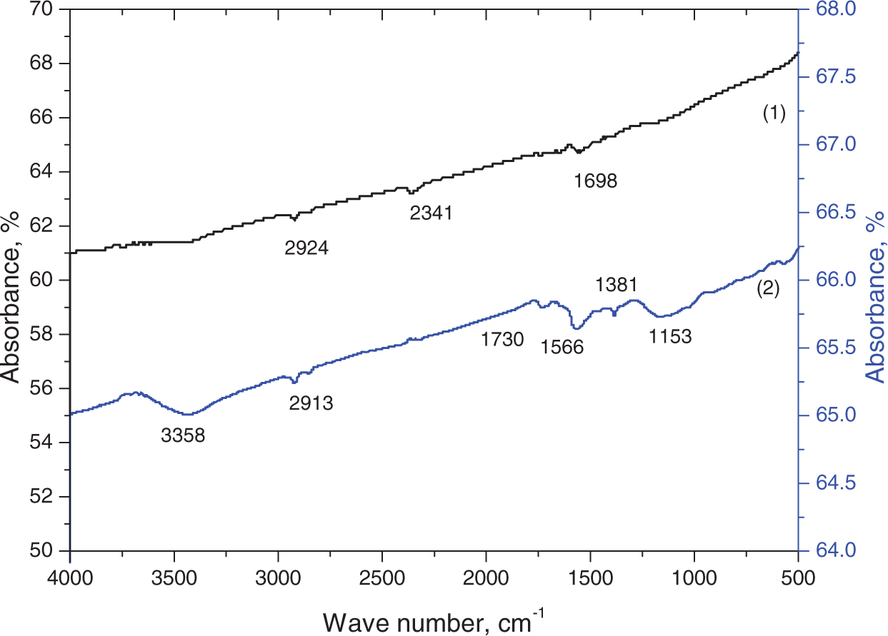
DSC Measurements
The effects of incorporating CNTs and f-CNTs on the crystallization behavior of iPP at a cooling rate of 5°C min−1 were investigated by nonisothermal DSC studies. Figure 2 shows the thermograms of the nanocomposites. The cooling curves show that on incorporation of CNTs, crystallization of iPP occurs at a higher temperature and the peak becomes narrower. It indicates that CNTs act as nuclei for crystallization of the polyolefin resulting in more uniform distribution of crystallite sizes. It is evident from Table 1 that the crystallization temperature of iPP shifts to a higher temperature on incorporation of CNTs. It has been reported earlier that CNTs function as a nucleating agent in crystallization of iPP [31].
DSC thermograms of nonisothermal crystallization: (a) cooling curves and (b) melting curves of CNT and f-CNT, both at 1 wt% filler loading. Crystallization temperature (Tc), crystallization enthalpy (ΔH), and the degree of crystallinity (Xc) of PP, iPP/CNT, and iPP/ f-CNT nanocomposites. The values within parentheses correspond to the composites with f-CNTs.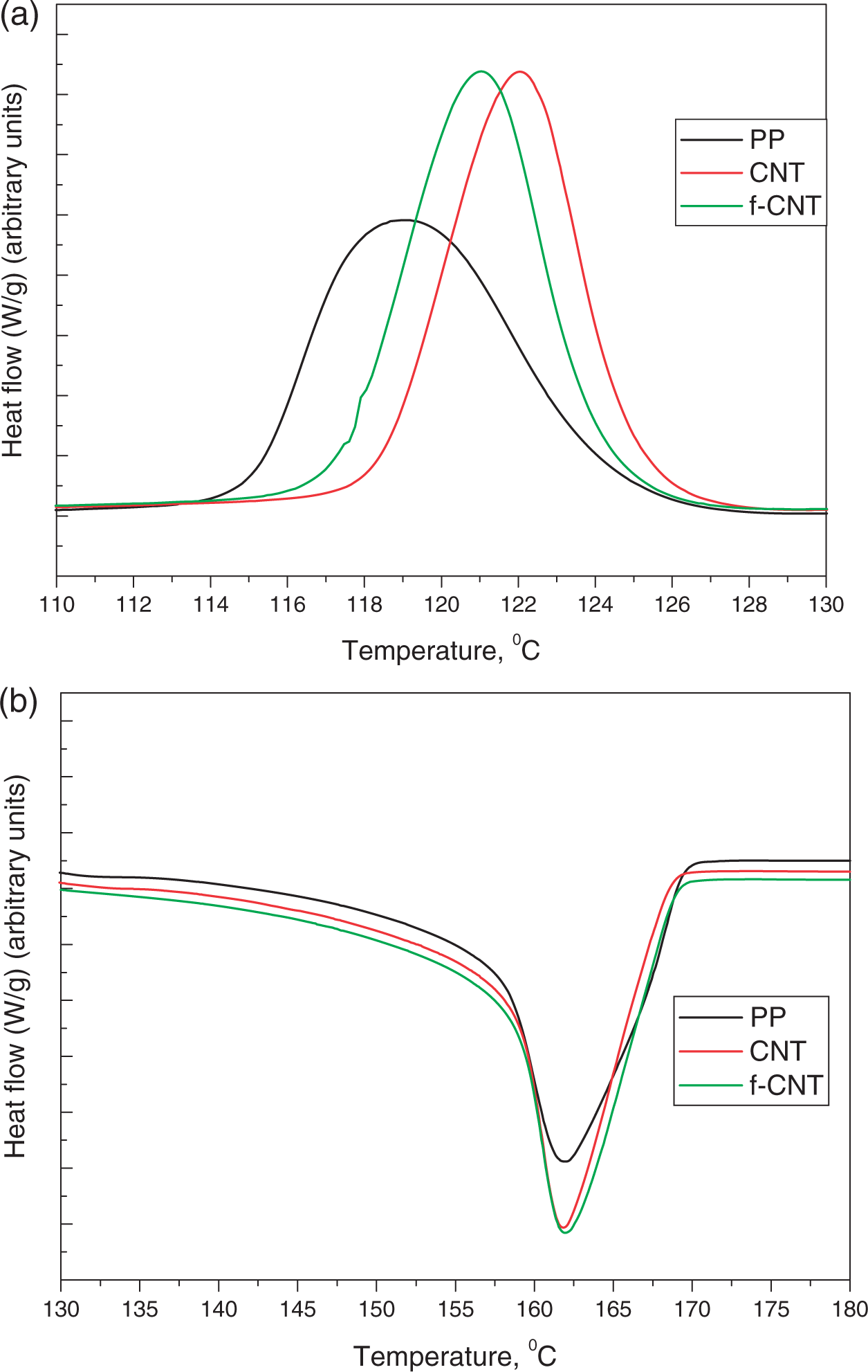
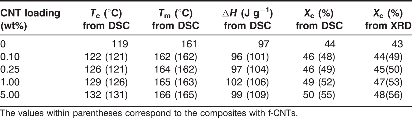
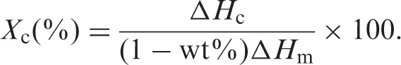
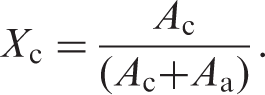
The degree of crystallinity (Xc) of the composites was evaluated from heat evolved during crystallization (ΔHc) using the relationship:
XRD Measurements
Figure 3 shows the XRD pattern of neat iPP and composites with 0.1 and 1 wt% of CNTs and f-CNTs. The peaks at 2θ = 14.1°, 16.9°, 18.6°, 21.2°, 21.9°, 25.5°, and 28.6° correspond to the planes (1 1 0), (0 4 0), (1 3 0), (1 1 1), (1 3 1), (0 4 1), (1 5 0), (0 6 0), and (2 2 0), respectively, of the α form of PP [31]. For PP and composites fabricated under our experimental conditions, the β form of PP (peak at 2θ = 16.2°) could hardly be detected. For PP, the (1 1 0) peak is more intense than the (0 4 0) peak; for the various composites, the intensities of the two peaks are nearly the same. The degree of crystallinity was calculated from XRD peaks and is close to what was obtained from DSC measurements (Table 1). The degree of crystallinity of samples was quantitatively estimated following the method of Nara and Komiya [33]. A smooth curve which connected peak baselines was computer-plotted on the diffractograms. The area above the smooth curve was taken as the crystalline portion, and the lower area between the smooth curve and the linear baseline which connected the two points of intensity 2θ of 30° and 10° in the samples was taken as the amorphous section. The upper diffraction peak area and the total diffraction area over the diffraction angle 10–30° (2θ) were integrated using Smadchrom software (Morgan and Kennedy Research, Australia). The ratio of upper area to total diffraction was taken as the degree of crystallinity.
XRD patterns of iPP composites with (a) CNT and (b) f-CNT, both at 1 wt% filler loading.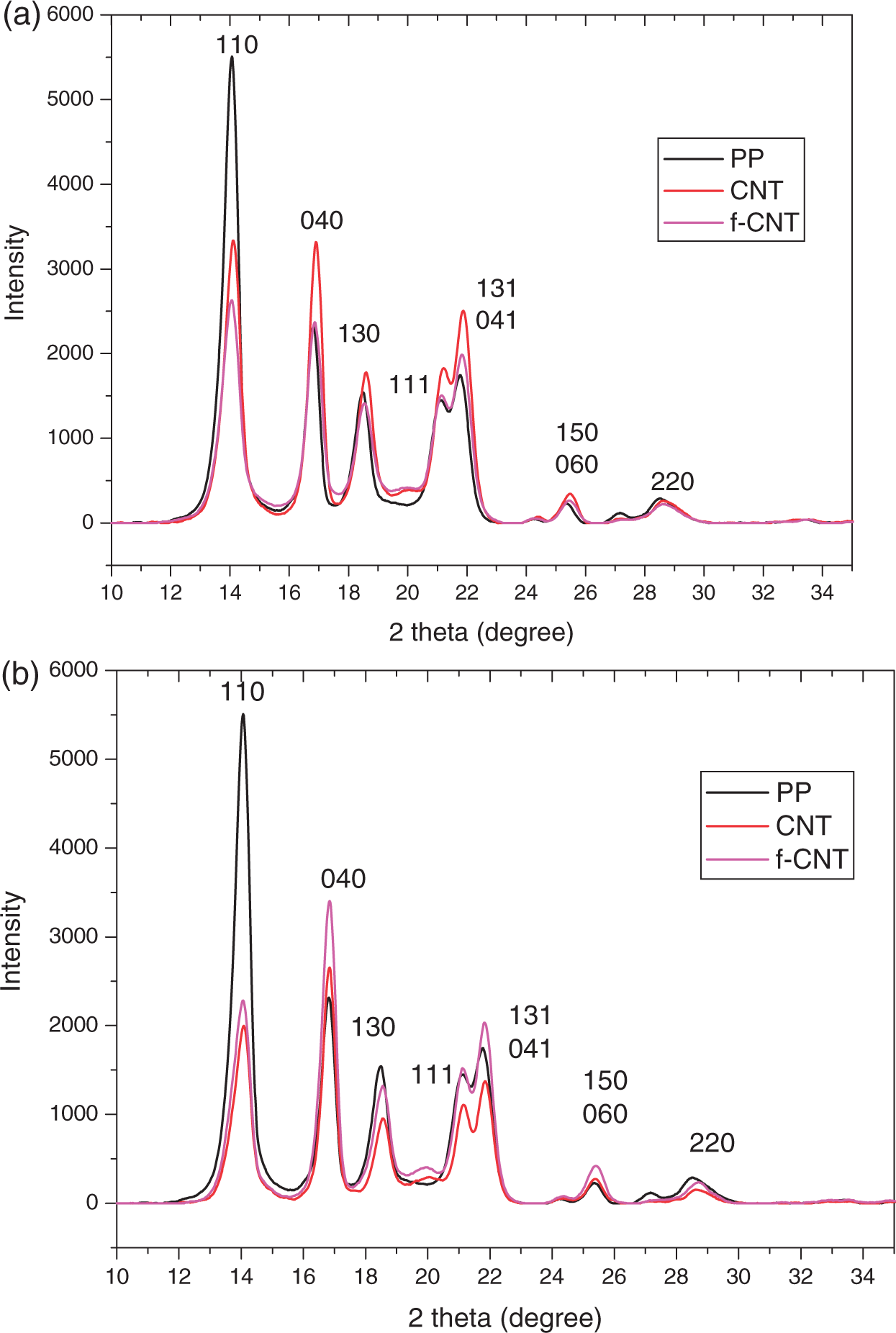
The degree of crystallinity was calculated as follows:
Mechanical Properties
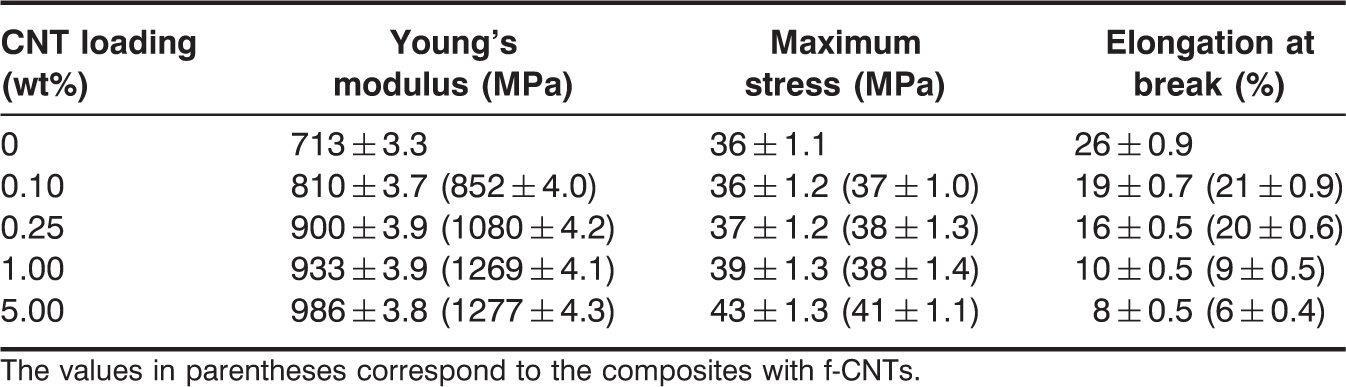
Stress–strain plots of iPP and its composites are given in Figure 4 and the results are summarized in Table 2. The Young's modulus of the composites increases with an increase in CNT loading and the effect is pronounced in the case of f-CNTs. High degree of dispersion of CNTs in iPP is believed to be responsible for the remarkable improvement in the Young's modulus of the composites. Maximum stress of the composites increases marginally with CNT loading and the effect is pronounced at high loading (i.e., 5 wt%). Incorporation of nanotubes in iPP decreased the elongation at break, making the composites less ductile and the effect is pronounced at >0.25%. It is also evident that the surface functionalization of CNTs causes an increase in maximum stress along with an increase in elongation at break up to a loading of 0.25%. At higher loading (1 wt% and above), both maximum stress and elongation at break decrease, indicating a fall in ductility. This observation shows that the failure properties of the composites are strongly dependent on the nano-filler loading, irrespective of the surface functionalization and increase in matrix crystallinity. At higher CNT loading, filler–filler agglomerates are likely to act as stress-concentrating sites.
Stress–strain curves of iPP composites with CNT and f-CNT, both at varying filler loadings. Summary of mechanical properties of iPP and iPP/CNT and iPP/f-CNT composites. The values in parentheses correspond to the composites with f-CNTs.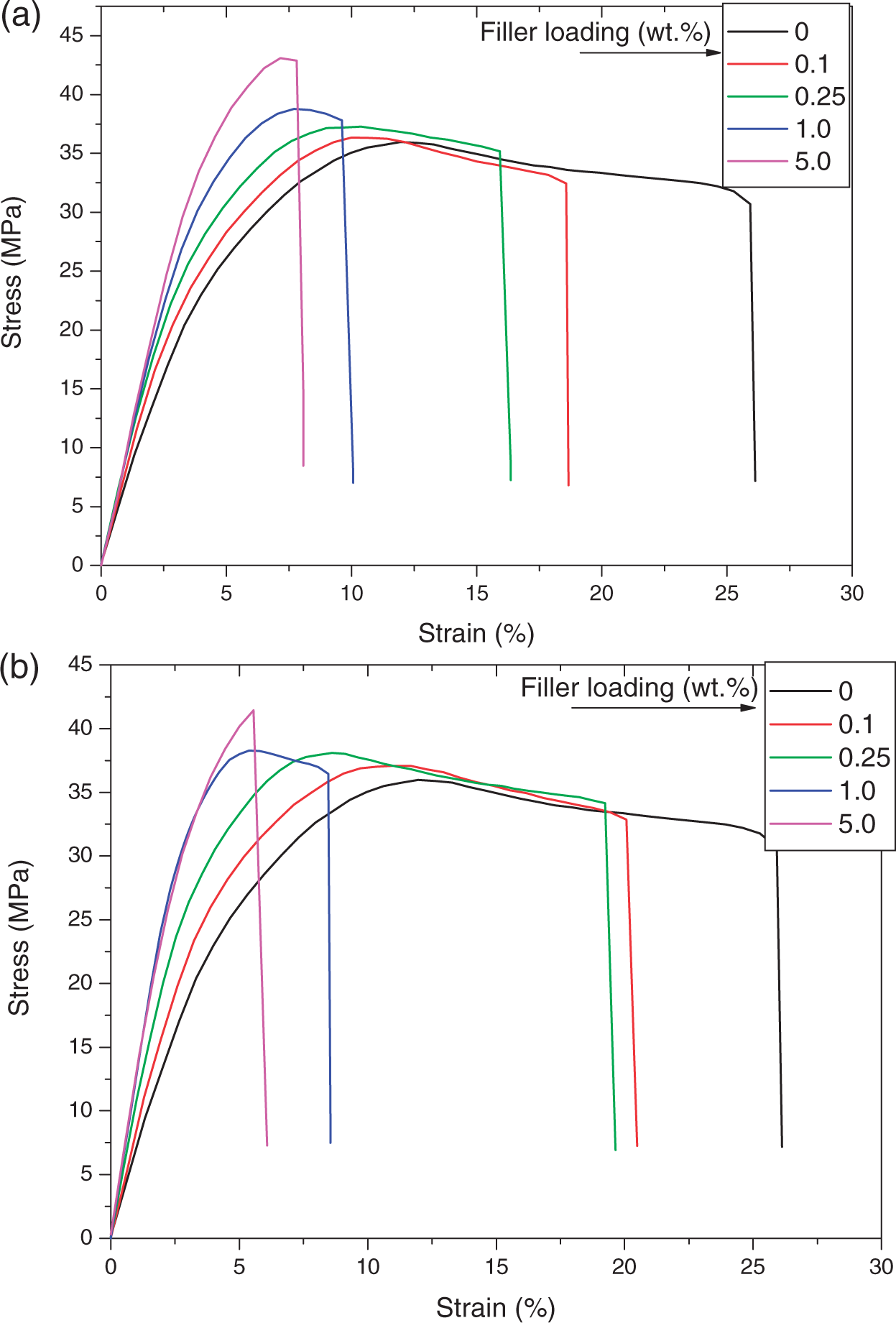
Dynamic Mechanical Properties
Dynamic mechanical properties of the composites with respect to filler loading are given in Figures 5 and 6. The storage modulus increases on incorporation of CNTs into iPP matrix. The effect is pronounced in the low-temperature region and more so with the f-CNTs. Table 3 presents the storage modulus of the 0.1 and 1 wt% composites at −20°C and 30°C. There is a significant improvement in the storage modulus for the composites with f-CNTs at both temperatures.
Storage modulus curves of iPP composites with CNT and f-CNT, both at 1 wt% filler loading. Loss modulus (a) and tan δ (b) curves of iPP composites with CNT and f-CNT, both at 1 wt% filler loading. Results of dynamic mechanical studies. The values in parentheses correspond to the composites with f-CNTs.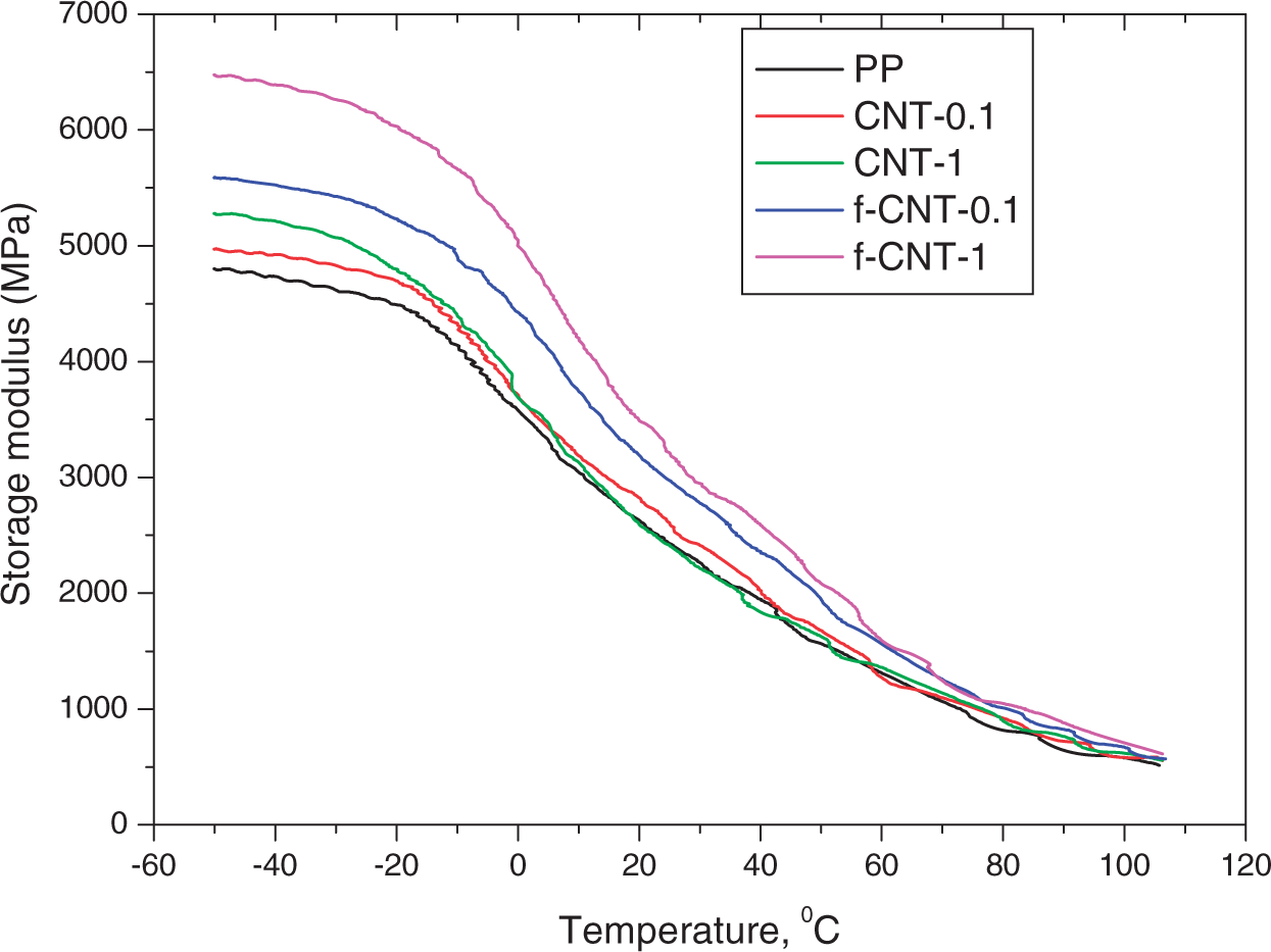
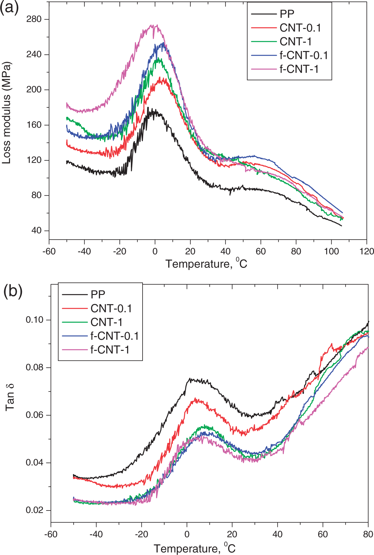
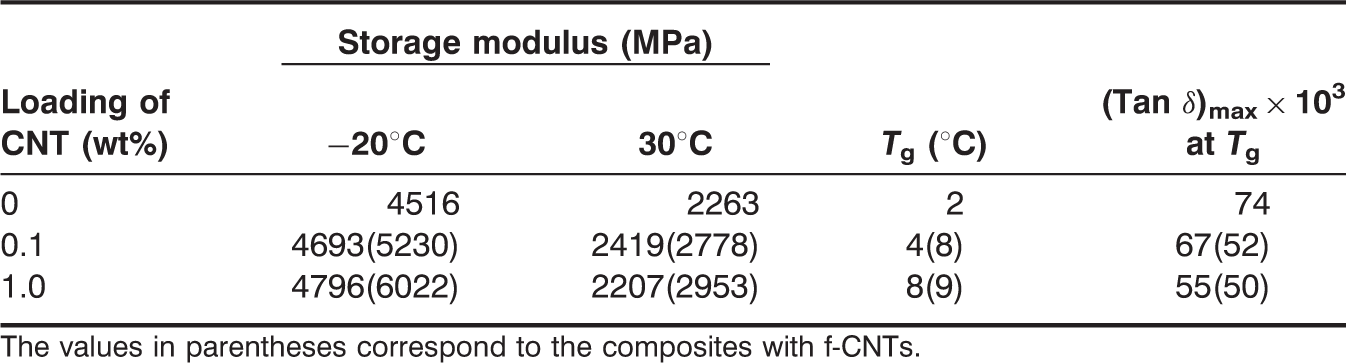
Figure 5 shows the loss modulus and tan δ peaks with respect to the filler loading. The loss modulus of the composites with f-CNTs shows higher values compared to the neat iPP. In the case of tan δ, iPP matrix shows the maximum value and with filler incorporation, the tan δ decreases. The decrease in tan δ with respect to filler loading indicates that there is enhancement in filler–matrix interaction, and particularly so in the case of f-CNTs. Table 3 presents the extent of decrease in the values of tan δ with respect to the filler loading at the glass transition temperature. The decrease in tan δ is more pronounced in the case of f-CNT composites. The shift in Tg to a higher temperature in the case of f-CNTs is believed to be due to greater filler–matrix adhesion.
Microscopic Studies
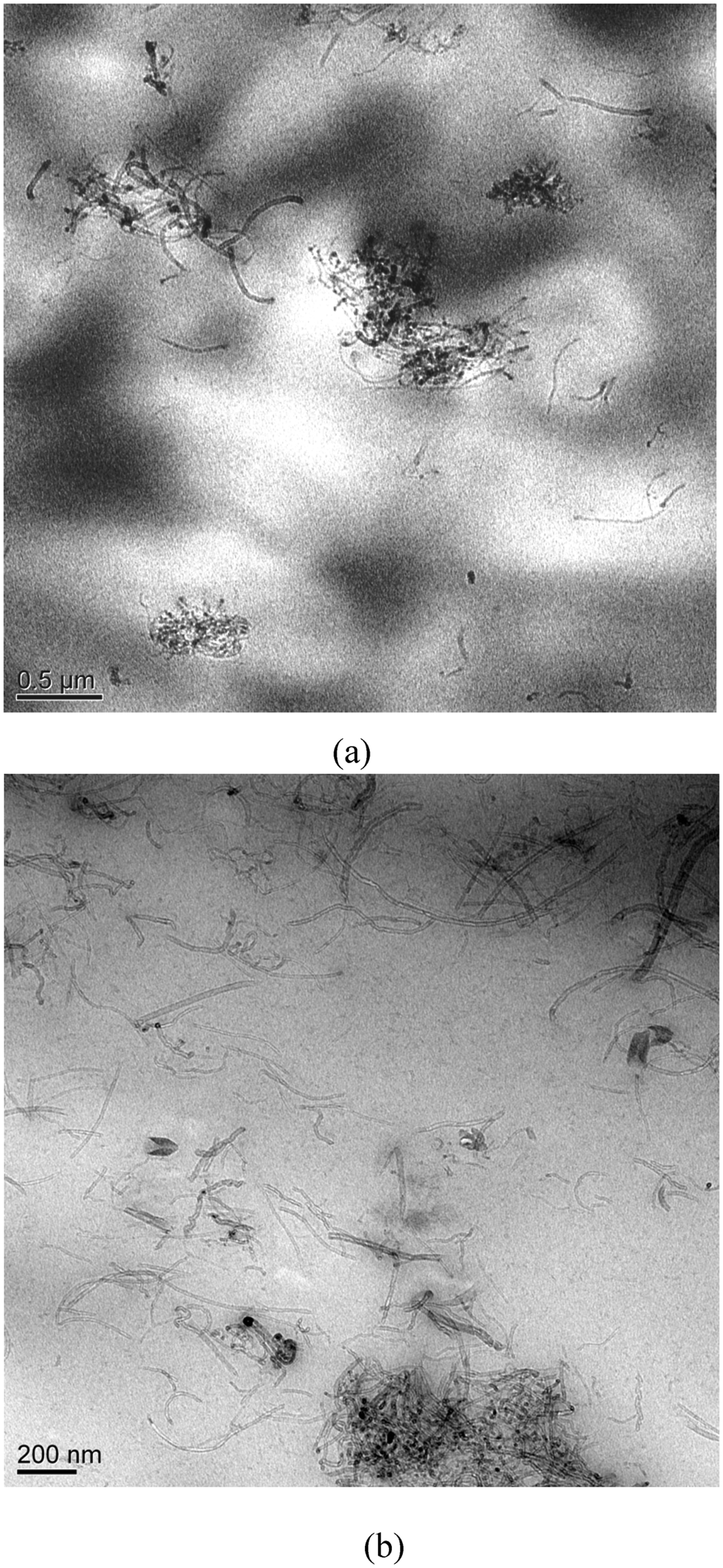
SEM of fractured surfaces of iPP and the composites are given in Figure 7. It is observed that the fractographs of the composites show less ductility than neat PP. This corroborates the findings of stress–strain measurements. Figure 8 shows the TEM images of the composites and it is evident that dispersion of CNTs in iPP is not uniform, even after surface functionalization. A few aggregates of both CNTs and f-CNTs are visible, which act as stress concentrators and account for the low ductility in high filler loading (>0.25%).
SEM micrographs of (a) iPP and iPP composites with (b) CNT and (c) f-CNT, both at 1 wt% filler loading. TEM images of 1 wt% composites of iPP with (a) CNT and (b) f-CNT, both at 1 wt% filler loading.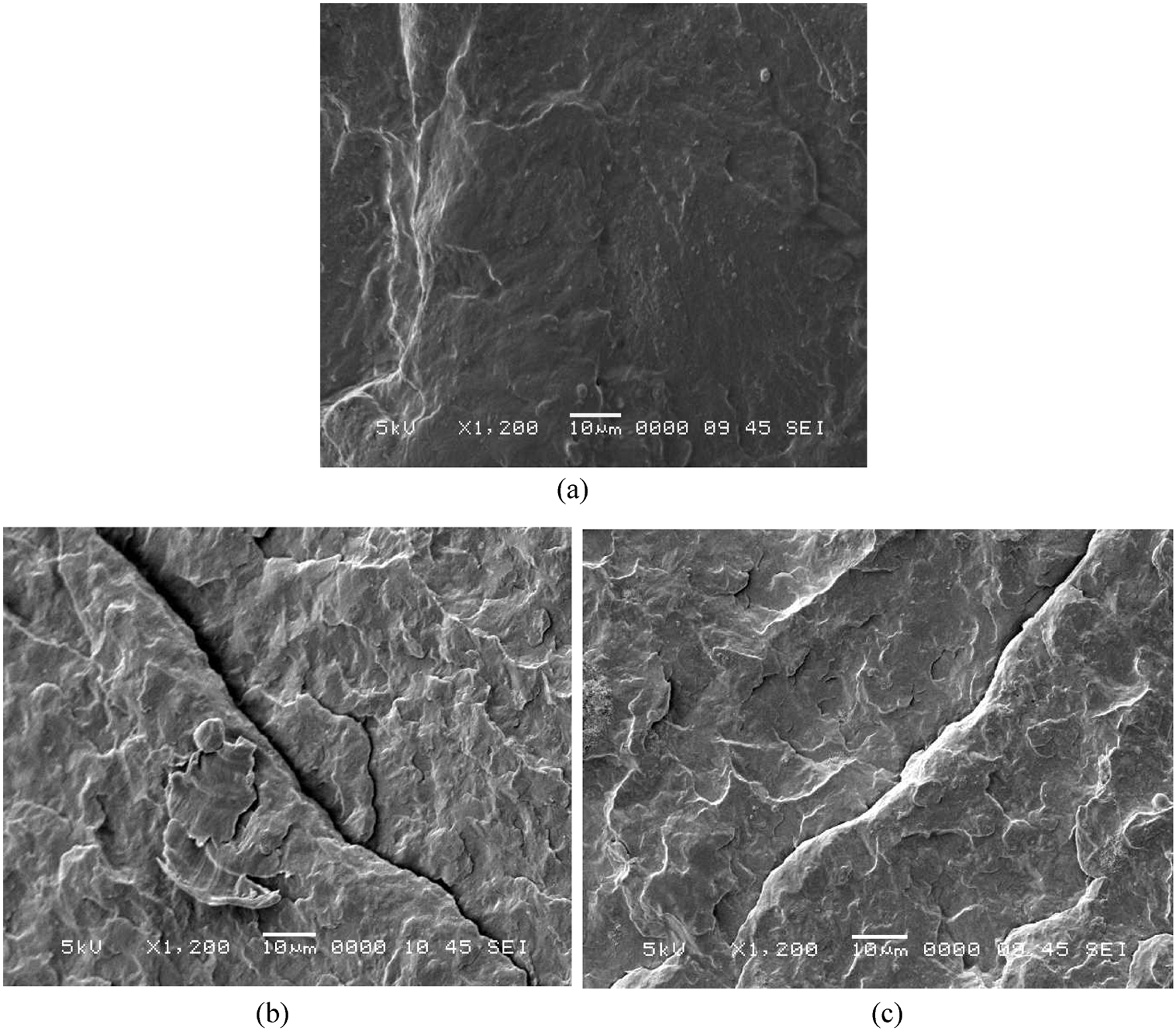
CONCLUSION
Both CNTs and –COOH functionalized CNTs (f-CNTs) increase the degree of crystallinity of iPP. Tensile modulus increases as CNT loading increases and the effect is pronounced in the case of f-CNTs. However, the effects of both CNTs and f-CNTs on the maximum stress are minimal. Elongation at break decreases on incorporation of CNTs, but the effect is pronounced in the case of f-CNTs and at high filler loading (>0.25%), resulting in brittle composites. Both storage and loss moduli increase and tan δ at Tg decreases due to enhanced matrix–filler bonding.