
Abstract
In the last decade, polymer nanofibers have found promising application for improving through-thickness properties of structural composite laminates through interleaving. The main advantage of inserting nanofibers in conventional composites is making the matrix between the layers tougher. In this article, the benefits of using electrospun fibrous nano-interleaves in enhancing the quasi-static indentation response of aramid/epoxy laminated composites was investigated and the effect of variables of produced nano-interleaves including interleaf thickness (17.5, 35, and 70 µm) and stacking configuration (one-side, central, and two-side interleaving) on behavior of the nano-modified composites was investigated. The results indicate that force, displacement, absorbed energy, and stiffness of these composites are significantly affected by the presence of nano-interleaves. The optimum values were observed in the composites with 35 µm thickness of nano-interleave where three first parameters were higher than their reference values, but the stiffness value had opposite trend of other parameters. On the other hand, it can be seen that only asymmetrical (back-side indentation) stacking configuration lead to improving the composite properties. The visual inspection of the indentation damaged specimens reveals that thickness and stacking configuration of interleaves controls the size of damage.
Introduction
Fiber-reinforced polymer composites (FRP) are increasingly used in different structural applications such as in the aerospace, marine, automotive, and construction industries. Numerous researches had been conducted to investigate potential of using various synthetic and natural fibers as reinforcement materials in composites. The main advantages of natural FRP are their availability from natural resources and biodegradability [1–3]. However, the prime drawback of these composites is their low mechanical strength compared to synthetic FRP. With the introduction of high performance fibers such as aramid fibers which possess high thermal stability and strength, these application in composite structures increased drastically [4].
The most common construction form of advanced FRP is laminated structure [5]. Severe problem of FRP-laminated structures is due to their poor interlaminar properties under traverse loading. This issue can be significantly reduced by improving the interlaminar fracture toughness and strength [6]. In recent years, nanofibrous mats have attracted great attention by scientists and industries to improve the through-thickness properties of laminated composites through interleaving [7]. Nanofibers offer several superior functional characteristics such as a very small diameter, large surface area-to-volume ratio, large porosity, and high flexibility [8]. Therefore, nanofibers can be easily impregnated with resin at low contents and also can take the shape of the primary microfibrous reinforcement. Consequently, they don’t have any considerable effect on the content or the geometry of microfibers in the composites [9]. Furthermore, the nanofibrous mat keep its structure and shape in the composite, and the problem associated with dispersion of nanoparticles in the resin which may influence the dispersion or change in the viscosity of resin will not exist [10]. For these reasons, nanofibrous mats could be easily employed in resin-rich interlayer between the reinforcing layers prior to composite production and consequently promoting the load transfer efficiency between them [11]. Electrospinning is considered as the most popular technique of producing these nanofiber-based materials. In this process, fibers are produced by the application of electrostatic forces to a jetting polymer solution [12].
Since the patent of Dzenis and Reneker [13] about interlayer toughening of composites using electrospun nanofibers in 2001, very limited papers can be found on composite laminates interleaved with electrospun nanofibers. Until now, most researches has been concentrated on the effect of interleaved nanofibers on composites reinforced with inorganic fibers including graphite [13], glass [14–16], and carbon [9, 17–24] fibers and there is no report regarding the response of aramid fiber reinforced composites containing toughen interleaves. The importance of aramid (poly(p-phenylene terephthalamide)) fibers (i.e., Kevlar™ and Twaron™) in the reinforcement of polymer composites has been revealed for several decades [25]. Aramid fibers have a unique combination of low density, high strength, and high energy absorption that rivals the properties of inorganic reinforcing fibers. Compared with the inorganic fibers, aramid fibers have the ease-of-processibility of organic fibers with higher elongation at break leading to even better energy absorption [26, 27]. According to Iqbal et al. [28] and Reis et al. [29], there is an opposite tendency in carbon/epoxy and aramid/epoxy laminates when their brittle epoxy matrix was directly toughened with nanoparticles. This is because of significance difference in the mechanical properties between carbon and aramid fibers. In fact, the aramid fibers do not fail by brittle failure, as do carbon or glass fibers. Instead, they fail essentially by a series of small fibril failures. These many small failures absorb much energy and, therefore, result in very high toughness. According to Aktaş et al. [30], the carbon or the glass fiber reinforced composites have brittle nature and show low energy absorption compared to aramid composites. Thus, the main energy absorption mechanism for glass and carbon fiber reinforced composites is fiber breakage mode, while for aramid composites it is essentially by delamination.
So far, many polymers have been electrospun and tested as interleaving material. However, nylon 66 was proved to be the most suitable for the purpose of reinforcing epoxy-based composites, due to its good mechanical properties, processability, and high melting temperature, which allows the nanofibers to maintain their morphology during the most common composite’s curing processes. Furthermore, nylon 66 has chemical compatibility with the epoxy matrix [31, 32]. Consequently, in this study nylon 66 was chosen for manufacturing nanofibrous-interleaves.
All of the preceding works in the area of nanofiber interleaved composites also have been devoted to evaluating the interlaminar fracture toughness through low velocity impact (LVI), double cantilever beam (DCB), and end notched flexure (ENF) tests. However, according to published studies, quasi-static indentation (QSI) test can adequately mimic the damage induced via LVI testing and detects more easily damage initiation and propagation [33, 34]. As a result, in the present study, the prospect of electrospun nylon 66 nanofibers in promoting through-thickness properties of aramid/epoxy laminated composites via examining QSI response was investigated. Furthermore, the effect of variables of produced nano-interleaves including interleaf thickness and stacking configuration on the behavior of the nano-modified composites were evaluated.
Materials and methods
Materials
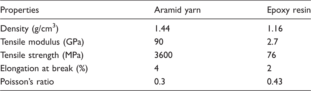
Physical and mechanical properties of components.
Electrospinning
The PA66 nanofibers were prepared using an electrospinning apparatus (Nanoazma Co.) consisting of two separate electrospinning sources around a rotating stainless steel drum collector (diameter 10 cm, wrapped with an aluminum foil). Each independent electrospinning source was composed of a high-voltage power supply, a 5 mL syringe fixed horizontally on the syringe stand and equipped with a stainless-steel blunt-ended hypodermic needle (19 gauge) and a syringe pump.
The polymeric solution was prepared by dissolving 15 wt% PA66 chips in a mixture of formic acid/chloroform (3:1 v/v) using magnetic Stirrer at room temperature overnight. The solution was fed at a rate of 1.5 mL/h from both syringes, and the tip-to-collector distance and collector speed were adjusted 18 cm and 100 rpm, respectively. A voltage of 25 kV was applied directly to the needles. By varying electrospinning time, three samples were obtained with 2, 4, and 8 h. All the experiments were performed at room temperature. All experimental parameters were chosen according to earlier studies [35, 36] and an optimization of a series experiments.
Laminate fabrication
Composite laminate plates were produced by hand lay-up of eight plies of Twaron fabrics with stacking sequence [(0, 90)/(+45, −45)]4, in which PA66 nanofibrous layers were inserted in particular interfaces. The designations (0, 90) and (+45, −45) represent a single layer of woven fabric with the warp and weft fibers being oriented at the specified angles. The composite with the selected stacking sequence has large difference of angle between two adjacent plies and therefore, will experience high impact resistance, but increased delamination damage. Because incorporating interleaves into a laminate result in improving the delamination resistance, so the selected configuration shows the effect of interleaves better. Four types of nanofibers stacking configurations were designed for this work, a virgin configuration and three nanofiber-modified configurations with different interleaf sequences (Figure 1).
Designed configurations of interleaf stacking: (a) Virgin, (b) IL1, (c) IL2, and (d) IL3.
The virgin configuration is reference laminate without nanofibers with eight Twaron fabrics alone (Figure 1(a)), which was fabricated as the control sample for the purpose of comparison. The next configuration is one-side interleaving (Figure 1(b)), in which the nanofibrous mats are inserted into three interfaces on the back side of indentation (IL1 configuration). With respect to similarity between QSI test and drop-weight impact testing, this configuration for interleaf stacking was stemmed from popular effect of LVI in thin laminates. In this case, the highest stresses as bending are induced at the opposite plies of the impacted side of the laminate, which cause matrix cracks and delaminations, and damage progresses from the nonimpacted face up toward the impactor giving a reverse pine tree appearance (Figure 2) [37, 38]. Therefore, the bottom-side interleaving (IL1 configuration) is considered on interfaces which are more prone to delamination. The third sample, configuration is central interleaving (Figure 1(c)), in which the nanofibrous mats were symmetrically inserted into the three central interfaces of the laminate (IL2 configuration). The sample four, configuration is two side interleaving (Figure 1(d)), in which the nanofibrous mats were symmetrically located on the two-side interfaces of the laminate (IL3 configuration). For simplicity, these interleaved laminates are referred as Asymmetrical (Asym) for IL1, Central symmetrical (Sym) for IL2, and Two-side symmetrical (SSym) for IL3 samples, respectively. In asymmetric sample, the thickness of nanofibrous web was varied and three different samples with nanofibers of 17.5, 35, and 70 µm were fabricated. They are referred as Asym17.5, Asym35, and Asym70, respectively. The interleave thickness of “Sym” and “SSym” specimens was only 35 µm.
Damage pattern for thin laminates.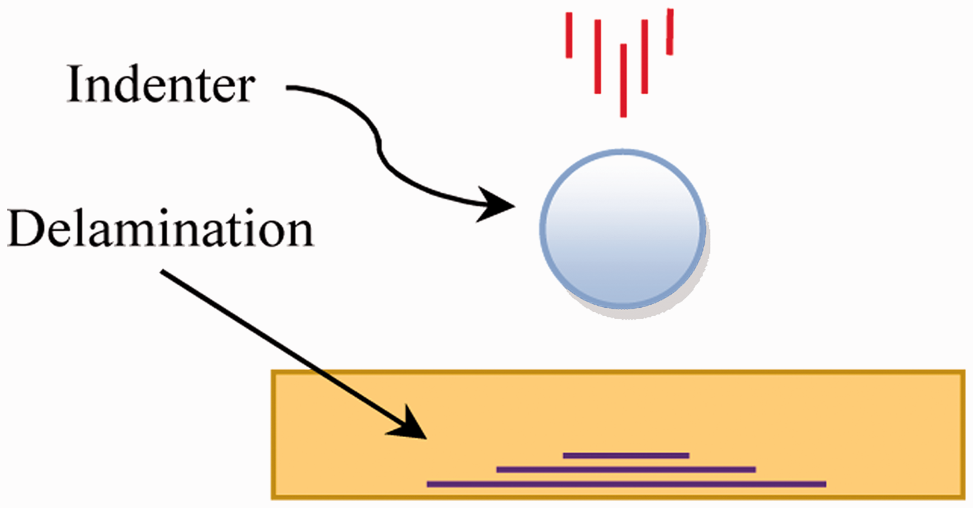
Based on the curing instructions provided by epoxy resin supplier, all the composite plates were initially cured at 25℃ for 24 h under constant pressure of 13 ± 0.15 kPa and then were postcured at 25℃ for 6 days. The thickness of the fabricated composite plates was 2.34 ± 0.08 mm. The nano-interleaves did not cause a noticeable change in the thickness of the samples.
Quasi static indentation tests
The QSI tests were conducted by a 250 kN universal testing machine (Zwick 1494, Germany) according to the ASTM D6264 standard [39]. Generally, in this test, a flat, square composite panel is subjected to an out-of plane, concentrated force by slowly compressing a displacement-controlled hemispherical-tip indenter into the face of specimen (Figure 3(a) and (b)). The indentation force is applied onto the specimen with four edges being clamped. Square specimens (150 mm × 150 mm) were bolted between two steel rectangular support-plates (200 mm × 300 mm and 14.6 mm thick) with central square apertures (100 mm × 100 mm) (Figure 3(c)). The diameter of indenter was 12.7 mm (Figure 3(d)) and a constant loading rate of 5 mm/min is applied to the center of the specimen in all experiments. A continuous loading approach was used during the test. In this approach, indentation force was applied continuously until the final failure (penetration) of the specimen and then the test machine stopped. For each specimen, five tests were conducted and the average is reported as the result.
Experimental setup for QSI test: (a) overall view of the machine, (b) closer view of the indentation, (c) indenter, and (d) support fixture.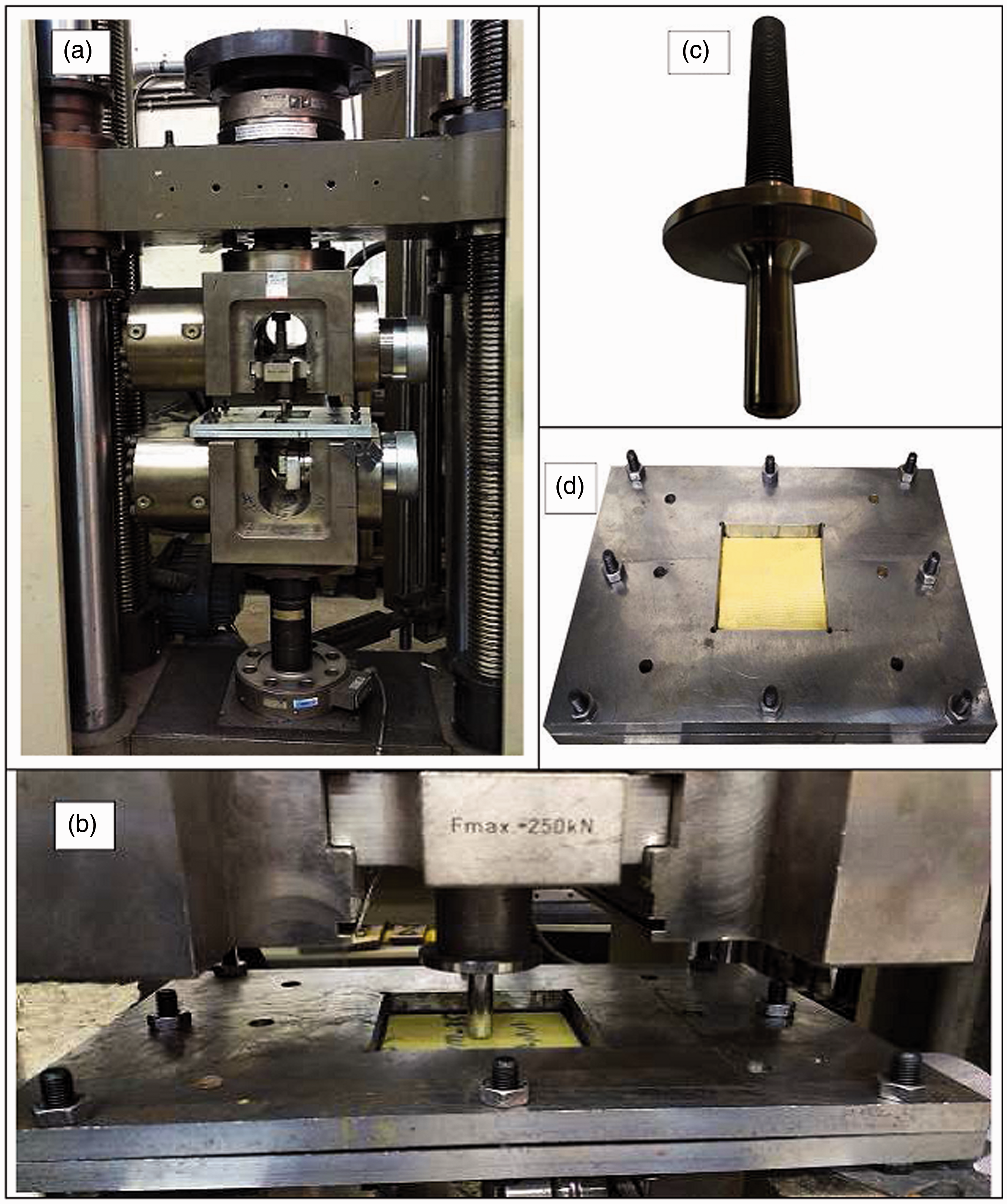
The contact force versus indenter displacement and time values were recorded during the indentation tests, till penetrating indenter into the test specimen. A typical quasi-static force (F)—displacement (δ) curve obtained from instrumented indentation testing is shown in Figure 4. In this curve, important milestones during indentation event were indicated. Main events include the incipient force (Fi) (representing the onset of internal damage, delamination threshold load and gradual loss of stiffness of the composite), peak force (Fmax) (representing the start of damage propagation and sharp decline in force and stiffness of the composite) and maximum displacement (δmax) (representing the indenter displacement at, or as near as possible to, the moment of penetration). Presence of small fluctuations in the first section of the some loading curves is the result of vibrations of the specimen-indenter system [40]. From the basic F–δ data, important parameters such as stiffness and absorbed energy were also calculated. Stiffness of the laminates was calculated from slope of F–δ curve in quasi-elastic region. The absorbed energy at any indenter displacement, δ, was calculated by integrating the F–δ curves using the following equation
Typical force–displacement curve.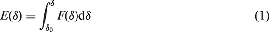

However, one characteristic feature was noted. It is the maximum energy (Emax) which is the energy required for the indenter to reach its maximum displacement on F–δ curve (δmax). This energy is represented as the overall area bounded by the loading curve

After the indentation tests, the samples were studied by using nondestructive digital microscope (Dino-Lite Premier) testing method.
Characterization of nanofibers
The samples of electrospun mats were gold sputtered and analyzed using a scanning electron microscope (SEM, Philips XL-30, Holland) operating at an accelerating voltage of 25 kV. The nanofibers were uniform without beads formation and were randomly oriented in a nonwoven mat (Figure 5). The diameters of nanofibers were determined by measuring 100 fiber diameters, with Image J software (NIH, USA) from the SEM photographs. The average diameters of nanofibers were 116 ± 25 nm. The thicknesses of the nanofibrous mats were measured using a digital micrometer. The resulting mats were approximately 17.5, 35, and 70 µm in thickness for electrospinning time of 2, 4, and 8 h, respectively.
SEM image of a nylon 66 nanofibrous mat.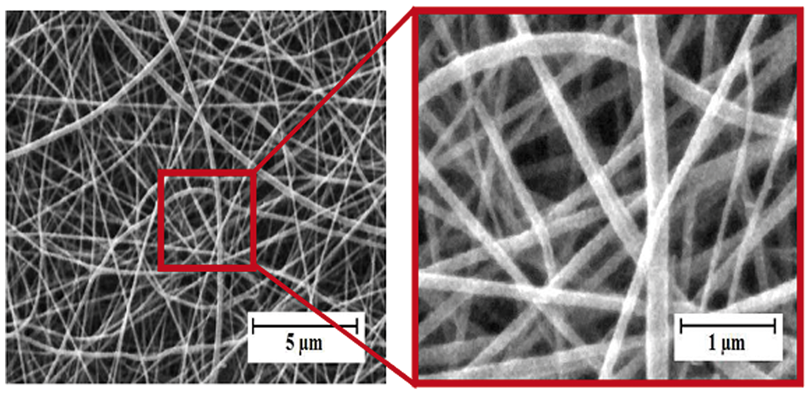
Results and discussion
Effect of nano-interleave thickness on force and displacement
Figure 6 shows the variation of quasi-static force versus indenter displacement for various specimens and the results are tabulated in Table 2. It can be observed that Fi and Fmax values increased for nano-interleave of 17.5–35 µm, and these parameters reduce beyond this point. At nano-interleave thickness of 17.5 µm, Fi went up by 37%, while it significantly increased by 57% for sample with nanofibers of higher thickness (35 µm). Despite Fi decrease for sample with nanofibers of 70 µm thickness, it is still higher than the virgin specimen. This improvement is observed at Fmax test results by 17% and 28% rise at 17.5 and 35 µm thicknesses, respectively.
Diagram of force versus displacement for interleaved specimens with different thickness. Characteristics of indentation events for various specimens.

Similar trend is also observed from test results of displacement at Fi (δi), displacement at Fmax (δf) and δmax. It can be seen that the addition of nano-interleave thickness up to 35 µm significantly improved the various displacement values. The highest displacement values were found at 35 µm where their improvement was 38%, 20%, and 14% for δi, δf, and δmax, respectively.
Above results are attributed to improvement in interlayer toughness, which is caused by the presence of nanofibrous interleaves. It can be seen that increase percentage of Fi and δi parameters are higher than Fmax and δf, respectively. It can be concluded that inserting nanofibrous webs into composites have more effect on delamination threshold load corresponding to damage propagation load.
Effect of nano-interleave thickness on the stiffness and absorbed energy
The stiffness and absorbed energy of various specimens.

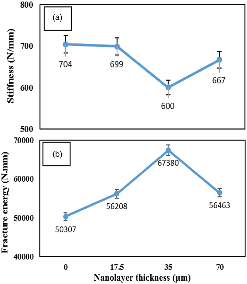
Effect of interleave thickness on (a) stiffness and (b) absorbed energy of composites.
Figure 7(b) shows the effect of nano-interleave thickness on the absorbed energy of composites. The values of the absorbed energy for interleaved composites increase toward a maximum when nanofibers of 35 µm thickness is used and then decrease with a further increase of nano-interleave thickness. At nano-interleave thickness of 17.5 µm, Ei went up by 46%, while it significantly increased by 105% at 35 µm thickness. Despite Ei decrease at 70 µm thickness, it is still higher than the virgin specimen. The results of Ef (energy at Fmax) tests exhibit improvement of 10% and 41% for 17.5 and 35 µm thicknesses, respectively. Note that 70 µm thickness contributes to increase 18% in Ef. This improvement is observed at Emax test results by 11% and 34% rise at 17.5 and 35 µm thicknesses, respectively. While Emax decrease at 70 µm thickness, it is 12% higher than the virgin specimen. Therefore, 35 µm thickness exhibits the highest absorbed energy, which coincides with the trend in the case of contact force and indenter displacement. These results are attributed to improvement in interlayer toughness, which is caused by the presence of nanofibrous interleaves. In can be seen that minimum value of composite stiffness is about 600 N/mm at 35 µm thickness of nano-interleave and when stiffness of improved composite was around this value, any more increase in thickness of interleaf lead to increasing stiffness, but decreased toughness. It was observed that enhancement of Ei parameter is higher than Emax and Ef, respectively. It can be concluded that inserting nanofibrous webs into composites have more effect on delamination threshold load corresponding to damage propagation load. These results are in good agreement with the force and displacement test results.
Occurrence times of indentation events for interleaved specimens with different thickness (second).

Effect of nano-interleave stacking configuration on force and displacement
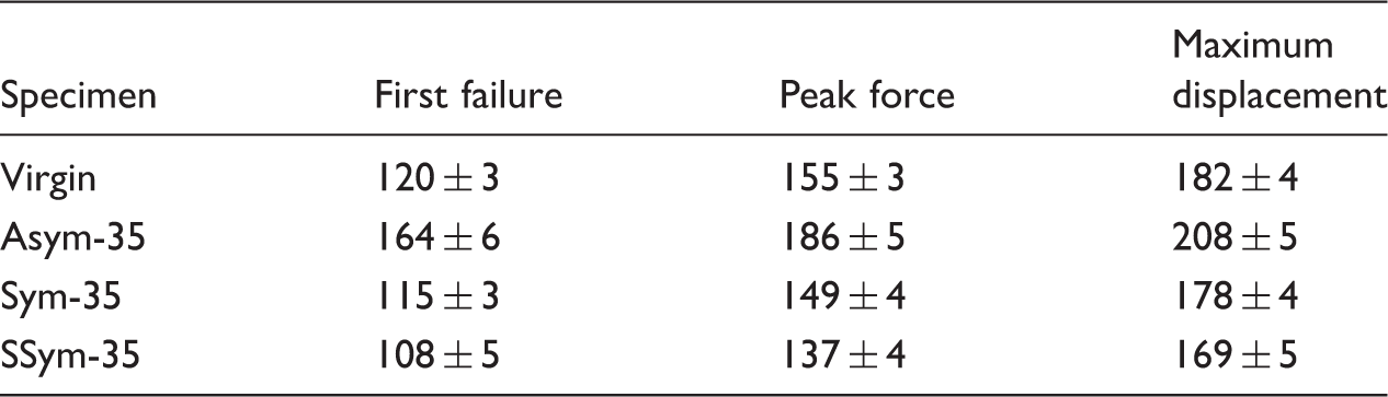
Comparison of F–δ curves of different interleaved configuration is shown in Figure 8. From these diagrams, it can summarize the values of the incipient force, maximum force, and indenter displacement in Table 5. It was observed that only asymmetrical configuration nano-interleaved specimen (Asym-35) contributes to improve indentation parameters. This configuration was 57% and 28% more as compared to Fi and Fmax parameters of the virgin ones, respectively. Generally, the symmetrical configuration nano-interleaved specimens (Sym-35 and SSym-35) represent less Fi and Fmax parameters compared to the virgin specimen. A similar trend was observed from test results of δi, δf, and δmax. It can be seen that only asymmetrical configuration lead to enhancing the various displacement values. This improvement was 38%, 20%, and 14% for δi, δf, and δmax, respectively. On the contrary, the experimental results obtained in this work demonstrate that interleaving with symmetrical configuration decrease various displacement values.
Diagram of force versus displacement for interleaved specimens with different configuration. Characteristics of indentation events for various specimens.

Effect of nano-interleave stacking configuration on the stiffness and absorbed energy
The stiffness and absorbed energy of various specimens.

Occurrence times of indentation events for interleaved specimens with different stacking configuration (second).
Damage evaluation
The results of digital photography of the samples after QSI test is shown in Figure 9. It can be seen in all the samples, the diameter of damaged zone of the rear surface (Figure 9(a)) is larger than the front surface (Figure 9(b)). The high stresses as bending are induced at the opposite plies of the indented side of the laminate and therefore, led to larger convex deformation on the back side of the specimens. In rupture site of the rear face, fibers is bulged (Figure 9(c)), the broken fibers can be seen along a circle (Figure 9(a) to (c)). The image of the rear surface clearly indicates that the rupture was much localized with surrounding extended delamination. The delamination is equally extended in all directions surrounding the rupture site.
Schematic of damaged zone after QSI test: (a) rear view, (b) front view, and (c) side view.
Size of the damaged zone in rear surface (cm2).
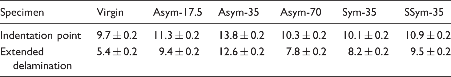
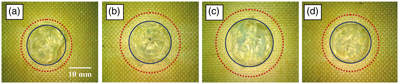
Schematic of damage in interleaved specimens with different thickness: (a) Virgin, (b) Asym-17.5, (c) Asym-35, (d) Asym-70; solid line: indentation point, dash line: extended delamination.

Schematic of damage in interleaved specimens with different stacking configuration: (a) Virgin, (b) Asym-35, (c) Sym-35, (d) SSym-35; solid line: indentation point, dash line: extended delamination.
Conclusion
Incorporating nanofibrous webs into epoxy/aramid fiber laminate can result in a significant increase in quasi-static indentation response owing to improving toughness of rich-resin interlaminar zone. The thickness and stacking configuration of the nano-interleaves influence on the effectiveness value. Inserting nano-interleave with optimum thickness of 35 µm provide the most value of toughness for the composite samples. In this condition, the composites go toward least stiffness and therefore, can withstand the indentation load in a ductile manner. Interleaving nanofibrous webs into composites have more effect on delamination threshold load compared to damage propagation load. The visual evaluation of the damaged specimens after the indentation test shows that the damaged area enhances with the increase of absorbed energy. Generally, the symmetrical configuration nano-interleaved specimens represent less toughness with respect to virgin specimen. It was shown that only asymmetrical configuration nano-interleaved specimen (back-side indentation) contributes to improve toughness.
Footnotes
Declaration of Conflicting Interests
The author(s) declared no potential conflicts of interest with respect to the research, authorship, and/or publication of this article.
Funding
The author(s) received no financial support for the research, authorship, and/or publication of this article.