
Abstract
In recent years, a growing interest in flexible electronic devices has been the origin of the formation of extensive research in providing the best method for the production of these tools. In this context, manufacturing of flexible textile antennas due to opportunities to integrate unique technical attributes with their applications is highly regarded by researchers. Therefore, in this paper, using inkjet printing technology with textiles and subsequently reducing it by metal nanoparticles with various deposition techniques to develop micro-layers of fabric has been suggested. It is anticipated that this method can produce electrically conductive textiles with flexibility and signal transmission in different wavelengths. According to the method in this article, after primary preparation of polyester fabric, it will print active materials with different designs at suitable operating conditions and then it will enter into the nickel electroless bath. The antenna having a conductive nickel fabric as ground plane was tested at different angles than receivers. That indicating zero degree angle relative to a line perpendicular to the surface of the antenna has the gain equal to −5.34 dB, because most of the antenna radiation field is perpendicular to the surface of the antenna. The most unsuitable degree is 90° angle, which is equal to −14.59 dB and shows that radiation from the sides of the antenna does not occur.
Introduction
In the past decade, signal transmission through wireless communication has played an important role in improving information technology. In this regard, the need for light and flexible electronic equipment in all areas of the electronics and telecommunications industry has increased more than ever. Accordingly, extensive research on flexible textile antennas attachable on clothing for information interchange wirelessly with a central station is an inevitable necessity [1] Antenna is a structure used for effective radiation of electromagnetic energy in the form of predetermined designs. In fact, without an efficient antenna, electromagnetic energy is collected in one place and transferring wireless data over long distances will be impossible. Because of the needs to send information by electromagnetic waves, many attempts have been made on the antennas and considerable progress has been made. Nowadays, we can see different types of antennas in different forms and dimensions, and the most important type of which is microstrip antenna. This kind of antenna was proposed in 1935 [1]. In this decade, antenna is not considered acceptable because of the problems in dielectric technology. Since 1970, efforts to improve the antenna have increased. Although the first practical microstrip antenna was made by Munson [2,3], these types of antennas have been pursued seriously since 1978, so that the first international conference on the topic of antenna was held in the United States. These antennas have received a lot of attention in recent decades for having significant advantages such as light weight, small volume, low cost, compatibility with integrated circuits, and creating multi-frequency [4]. These huge benefits can be used not only in military applications such as spacecraft, missilesand rockets, but also in commercial applications such as mobile satellite, local positioning systems, remote control [5]. The main disadvantages of microstrip antennas are their low efficiency, low power, and low frequency bandwidth range [6–8]. Among all available forms of patch antenna, rectangular and square patch or T-shaped combination is the most known form of conductive patch [9]. The importance of microstrip antennas due to their light weight and projecting on every woven and non-woven fabric is clear. Recently, wearable antennas play an important role in the personal communications technology [9,10]. There are various available methods which have been utilized to produce textile antennas which are based on textile fabrication process including, sewing [11], knitting [12], and embroidery [13]. One of the most fundamental problems of this type of antenna is using metal plates and embroidering conductive wire directly on woven or unwoven textile structures that would reduce the comfortableness of the final product. Among all of these methods, printing techniques such as Flexograghy, offset, Flatbed screen printing, Gravure and inkjet have been known successfully to create conductive patterns on various substances such as paper cases [14].The most famous of printing method is inkjet printing technology that if it operates with electroless plating bath, it will be able to produce high electrical conductive fabrics along with flexibility and comfortably [15,16]. Recent research by Mottaghitalab et al. [17] has shown that laminating method as well as a electroless deposition technique has a high rubbing and washing fastness in the environmental conditions.Other researches by Mottaghitalab and his co-wokers [18] from Yazd University have succeeded in making flexible sensors on the woven substrate as a glucose sensor using inkjet printing techniques [18]. In addition, the same technique that we used in this article was effective for producing the textile sensors for receiving signals from the heart [19] as well as other research-based inkjet printing investigated a textile conductive layer as super capacitors [20]. Using inkjet printing techniques and subsequently Ni electroless process for making wearable textile antennas was introduced by Mohtaram et al. [21]. In fact, they investigated the possibility of making microstrip antenna by textile materials. In recent years, a significant increase in the use of inkjet printing in the textile and electronics industry, particularly in the field of wireless communication, has been accessed. In the study, due to the advantages of inkjet printing in creating a conductive circuit, this type of printing method along with electroless deposition of nickel metal nanoparticles have been used. Also, the characteristics of printed antenna have been investigated at different bending angles by a spectroanalyzer device.
Materials and methods
Low-density polyethylene terephthalate (PET) fabrics (30 × 32 – score 88.8 warp and weft yarn denier) with a taffeta texture were used as background (substrate). The surface activation process requires a wide range of chemicals including non-ionic detergent (2 g/l), soda (NaOH, 15 g/l), tin chloride (SnCl2, 10 g/l), hydrochloric acid (HCL, 38%, 20 ml/l), chloride palladium (PdCl4, 0.04 g), nickel sulfate (NiSO4·6H2O,0.0056 M), sodium hypophosphite (NaH2PO2·H2O), boric acid (H3BO3, 0.072 M), sodium citrate (C6H5Na3O7·2H2O, 0.0116 M), hydrogen peroxide (H2O2, 0.042 M), ammonium chloride (NH4CL, 0.04 g), ethanol (C2H5OH, 1. 25 g), and twice-distilled water. Interestingly, all chemicals listed were purchased from the Merck company.
The method of preparing of textile printing
At first, the fabric is rinsed in a bath containing 2 g/l non-ionic detergent for removing oil and surface contamination at 30℃ for 10 min. Next, samples were washed with distilled water several times and then an immersion step in a 15 g/l NaOH at 70℃ to create sites for the deposition on fibers is considered, followed by rinsed several times with distilled water. According to the amount of consumed fabric density, required time and temperature are different. After that, the fabric entered into the solution of 10 g/l SnCl2 and 20 ml/l HCl (38%) at room temperature for 10 min until the sensitization campaign is carried out on the surface of the fabric. Finally, the fabric is rinsed with distilled water and is dried at the temperature of 120℃ for 15 min in an oven.
Preparation of printing ink
Palladium chloride (0.04 g) and 0.04 g of ammonium chloride in 23.7 ml twice distilled water are blended for 1 h at the rate of 300 r/min. Then 0.15 ml of the obtained yellow solution is taken and three drops of hydrogen peroxide in conjunction with 1.25 g of ethanol to prevent the precipitation of palladium ink were added. Admittedly, the prepared ink is stable at the temperature of 4℃ over a month. It is interesting to note that palladium ink should have similar viscosity and surface tension in comparison with the black ink of the printer.
Inkjet printing
We used a typical PC software program with Microsoft Office 2003 and a high-performance printer (HP Deskjet 1280, resolution 600 × 600 dpi, printing speed 6 ppm; DIN A3 format) for printing active aqueous solutions on fabric surface. Admittedly, the cartridges of mentioned printer are divided into color (HP78 tri-color inkjet printer cartridge) and black (HP45 black inkjet printer cartridge) which the black ones was used in the study for printing ink and process was done as reported in the literature [19]. In summary, at the first stage, the black cartridge was emptied and after washing with water, ethanol was filled with new palladium ink. Then, a PET sample was cut to a suitable size (5 × 5 cm2) and attached in paper for the printing process. In the next stage, patch geometry was designed and palladium ink had been printed on fabric surface for several times. After printing, the samples were put in a 0.1 M sodium borohydrate solution for 5 min as shown in Figure 1 and was followed by nickel deposition bath (deposition was done for 2 h at 70℃ and pH = 8.5). Table 1 shows the amount of substances used in the bath deposition of nickel. Finally, we used nickel-coated pattern on polyester fabric to make both patch and ground plane of proposed antenna.
Schematic diagram of Pd formation on polyester fabric via inkjet printing. The amount of materials in the plating bath for Ni coating on polyester fabric.

Characterization of PET fabric
The properties of fabric specimens before and after treatment were measured based on ASTM-D1777 [22] method and are shown in Table 1. Measuring the electrical resistance was done by a digital multimeter (ADM-552 R) based on four-probe method [19]. Also, determining the washing fastness of provided conductive fabric was done based on ISO 105-C06:1994 manner. In addition, Air Permeability Tester (model FX 3300 Air Permeability Tester III) was used to determine the air permeability of printed Ni pattern based on BS5, 636 method. Also, to study the surface morphology, sample electron microscope images were characterized by SEM (model Philips XL30 at 15 kV working voltage).It is interesting to note that all SEM samples were coated with a thin Ag layer before the operating. The chemical composition of the deposited layer was defined using energy dispersive X-ray (EDX) analysis connected to the SEM. Also, the spectrum analyzer (model Physio-control – Lifepak) was used for comparing the performance of the different printed antenna (relative losses and the gain). Figure 2 shows the image of used spectrumanalyzer as well as the method of attaching printed antenna for charactrization. By analyzing the spectrum signals, the bandwidth and signal strength of samples can be obtained. As a matter of fact, the amount of gain and bandwidth of the provided antennas were obtained by comparison with a standard antenna like isotropic antenna. To achieve this aim, the isotropic antenna was connected back to back to the spectromanalyzer.
Spectrumanalyzer images of printed antenna and connected manner.
Results and discussion
Fabric weight and thickness
Weight and thickness of the untreated and printed deposited polyester fabrics.
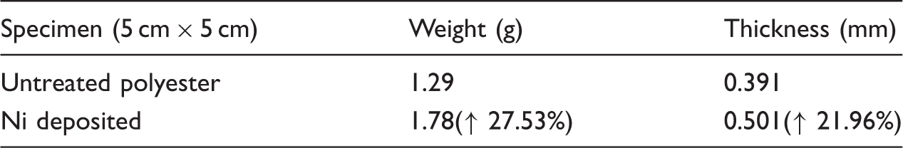
The obtained results show that the weight of chemically induced nickel-plated polyester fabric was heavier (by approximately 27.53%) than the untreated specimen. This evidence is the fact that nickel had effectively cleaved on the surface of polyester fabric. Also, the percentage of thickness of Ni deposited fabric increased 21.96% that exhibited an increase after being subjected to plating.
Fabric washing fastness
According to various applications of concuctive patterns like wireless body area network [23], determination of washing fastness of printed layer is essential. So, assessment of the stability of samples was repeated five times and after each test, the surface electrical resistance was measured. Figure 3 shows a diagram of washing results of deposite fabric.
Washing results of deposit fabric at different times.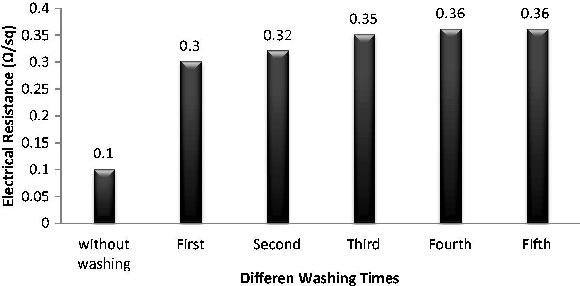
A glance at the graph provided reveals that by increasing the washing times of printed fabric, due to separation of Ni nanoparticles the electrical resistance has also slightly increased; moreover, after five washing times, the conductivity of samples has been proven. SEM images (Figure 4) of washing process confirmed the previous obtained information of the diagram.
SEM images of (a) unwashed Ni sample and(b) fifth washed sample.
Fabric air permeability
Air permeability of treated and untreated polyester fabric.

EDAX analysis
Elemental analysis of electroless nickel plated.


The EDX analysis of deposit nanoparticle.
The combined percentage of constituent layer elements on the polyester surface is shown in Table 4. It is evident from the information provided that 62.11% of all elements are related to nickel particles.
The process of deposition by ion hypophosphite as a reducing agent creates a dual alloy composed of Ni–P [24]. According to the amount of phosphorus in Ni–P layer, it is classified into three various categories: low (1–3 wt.%), medium (4–7 wt.%) and high (greater than 7 wt.%) [25]. Graham et al. [26] belived that the difference among chemical structure of covered layer was related to acidic and basic nature of the bath. Also, they showed the basic bath contained little phosphorus and higher conductivity compared to acidic bath.
Print Pd ink times
One of the main parameters for reaching reasonable conductivity is printing ink times. Figure 6 displays antenna patch images prepared by one to five times of printing. The electrical resistance of samples that were printed once (Figure 6(a)) in the best case has been reported 6.2 Ω/sq. In order to reduce resistance and raising conductivity of the sample, inkjet printing on polyester was performed five times (Figure 6(b)) and the resistance decreased to 1.8 Ω/sq without any significant changes in the print bound. It is obvious that the amount of deposited nickel on once printed case is less than five times. By increasing the number of printings, more ink was able to penetrate through the fibers, and finally, at the deposition stage, particles of nickel are presented more than before on the surface as shown in Figure 6(b). Figure 6(c) and (d) shows the cross-sectional area of the deposited once and five reprinting times on samples. In Figure 6(c) it is clear that the nickel does not reach the lower level of fabric completely, which indicates that once inkjet printing for particle deposition was not enough. At high magnification of images, uniformity and non-uniformity of nickel particle are also visible as well.
SEM images of deposited samples: (a) and (c) once printed case, (b) and (d) five times printed case.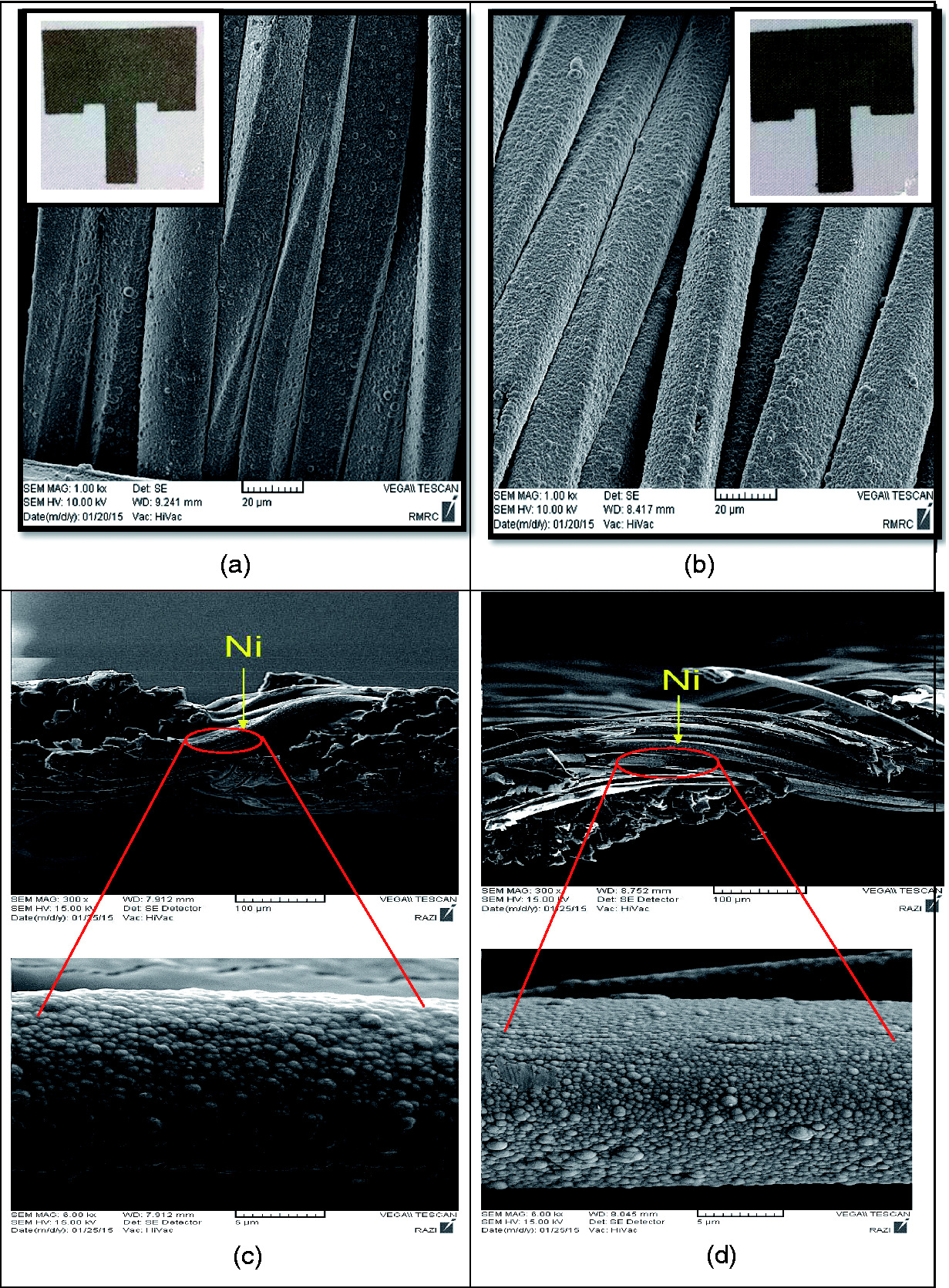
Figure 6(c) and (d) clearly shows nickel particles at cross-section that have been together and formed a nearly uniform layer of cauliflower after five times printing.
Antenna design and theory
Generally, a microstrip antenna was formed of three main elements named conductine patch, dielectric substrate, and conductive ground plane as shown in Figure 7(a). In this study, we used Ni metal nanoparticle as conductive material and deposited it on polyester surface by electroless plating method. There are different feeding techniques for microstrip patch antenna including coaxial connector [27], microstrip line [28], aperture coupling [27], and proximity coupling [29].One of the common feeding methods for planar fabrication is microstrip feed line. Hence, the antenna was fed by a 50 Ω microstrip line. Figure 7(b) illustrates the textile rectangular patch antenna. This type of feeding is used to control the resonant input resistance at the contact point. Accordingly, we designed this form of patch for additional experiments to assess the effect of the bending angle on the performance of wearable antennas.
(a) Microstrip patch antenna (b) top view of microstrip rectangular antenna.
A rectangular patch antenna was designed to resonate at 2.4 GHz on the polyester fabric substrate for facility of integration. The length and width of the antenna are given in Figure 8.
The dimensions of the patch antenna used in the antenna woven.
Dimensions including thickness and length of screw antenna and related table are presented in Figure 8. Then, prepared specimens were designed to resonate at 2400 MHz and were printed by inkjet printer on the above of polyester surface fabric. On the other hand, the mentioned substrate is attached to the ground plane and the length and width of the substrate were 63 mil and 50 mil. It is interesting to note that the behavior of a transmission line can be indicated by scattering parameters like gain and relative loss (S-parameters) that indicate how well the line is matched with the input ports. All samples were tested five times at a relative humidity of 32% and room temperature of 21℃.
Different positions of antenna
In the case of antenna, position mood between sender and receiver signal is an important issue, so that the angle between these two situations was focusing on this article. Rectangular textile patch antennas were designed and fabricated at a frequency of about 2400 MHz. All samples were fed by a 50 Ω microstrip line. After that, the sender (antenna) was fixed at six different angles of 0, 15, 30, 45, 60, 90° and was put in the transmitter antenna. Then some parameters such as gain, relative loss, and bandwidth were measured by the spectrumanalyzer device. Figure 9 compares the different angles between sender and receiver using the antenna with the nickel – ground plane. Obviously, the vertical axis indicates antenna gain (dB) and the horizontal axis represents the input frequency (MHz). It should be noted that this textile antenna resonates at a frequency of 2400 MHz.
The antenna gain as a function of frequency at different angles.
Antenna parameters.

As can be seen in Figure 10, the position of zero degrees relative to a line perpendicular to the surface of the transmitter antenna is more desirable than other angles since the radiation of most antennas is released from perpendicular of it. By increasing the angle between the two main antennas (receiver and sender signal), a growing relative loss is resulted in such a way that the weakest gain is related to 90° degree angle relative to a line perpendicular to the surface of the antenna. It is evident from the information provided in Figure 9 that the gain of zero degree antenna is −5.43 dB than receiver antenna, although the gain at 90° is equal to −14.59 dB. Consequently, higher angles have less gain and radiation compared to others. Table 5 shows the variation range of the gain and angle between the transmitter and receiver antenna.
The antenna relative loss as a function of frequency at different angles.
Conclusion
In this paper, firstly, the design and manufacturing of flexible microstrip antenna based on woven textile with a cceptable conductivity, mechanical, and physical properties were done. Modifying the micro structure of polyester surface by Ni plating process was clear in SEM images. The morphology study of Nickel-coated layer on polyester surface showed a uniform structure with a high density. The EDX results indicated the high percentage of coated materials related to Ni nanoparticles. Washing fastness and air permeability of samples have been tested as major parts of this article. From the information provided, it is evident that the washing fastness of samples decreased dramatically with increasing times due to the separation of Ni nanoparticles from the fabric surface. Also, air permeability results were the same as washing test because of the Ni dense coated layer. We tried to investigate performance characteristics of textile antenna in different bending angles. To achieve this goal, a T-shape antenna was printed on pre-treatment polyester fabric by using palladium and inkjet printing in optimum conditions (resolution 600 × 600 dpi, printing speed 6 ppm, five printing times) and then an electroless nickel plating bath was used for deposition of metal nanoparticles on the surface of fabric. Printed samples were dried at room temperature for 10 min and immersion occurred in a 0.1 M borohydrate solution at room temperature and finally they were put in the deposition bath at a temperature of 70℃ and pH = 8.5 for 2 h. The best printed sample was used as a conductive patch for microstrip antenna. Nickel nanoparticles-deposited fabric was used to prepare the final antenna as a ground plane. We investigated the signal spectrum, gain, and bandwidth using a spectrumanalyzer device at different angles. With this method, conductive design has a suitable electrical conductivity and resistance equal to 1.8 on polyester substrates.
The important part of antenna application is the position between the transmitter and receiver antenna. So, in this study, angles of 0, 15, 30, 45, 60, 90° to a line perpendicular to the antenna surface are studied. According to these measurements, the angle between the main position of zero degrees means when the receiver is perpendicular to the antenna surface, the antenna has the highest gain (−5.43 dB), the lowest relative loss and bandwidth (0.7 MHz) and in the position of 90° between them it has the lowest gain (−14.59 dB), the highest relative loss and bandwidth (1.03 MHz). The best position is when the receiver is perpendicular to the antenna surface.
Footnotes
Declaration of Conflicting Interests
The author(s) declared no potential conflicts of interest with respect to the research, authorship, and/or publication of this article.
Funding
The author(s) received no financial support for the research, authorship, and/or publication of this article.