
Abstract
Over-braiding of superconducting Rutherford cable was used for the composite insulation in this research. Braiding was a suitable alternative to fabric tape winding for achieving ultrathin insulation with required electrical breakdown voltage. A brief overview of the superconducting magnets, their application and requirements of insulation has been covered in order to bridge the literature gap between braiding and the superconducting magnet field of studies. Organic size coating on the fibre leaves carbon residue during high temperature treatment of the cables and hence glass fibre was desized before braiding. Braiding difficulties with desized glass fibre and possibility of braiding using compatible size coating have been discussed. The requirement of ultrathin braided layer was achieved with sufficient surface coverage with a suitable braid angle and fibre. As part of the study, braid cover factor variation on the surface of the cable was investigated and it was discussed using image analysis.
Keywords
Introduction
High performance fibre made textile substrates are widely used technical textiles for developing composite materials. The textile substrates used as reinforcement in composites are typically made using conventional textile manufacturing technologies such as weaving, braiding and winding. Composites are used mostly in the lightweight materials application such as for structural components in aerospace and automotive components [1], cylindrical structures, marine and railway structures, turbines, sports equipment and so on. Yet another field for composite application has been electrical insulation of cables for electromagnets operating at cryogenic temperature. Electrical insulation can be provided by the polymer or ceramic cover. However, insulation for superconducting cables requires a significant amount of load bearing capability that can be achieved by fibre-reinforced composites. Glass fibre tape winding is a widely used method for developing such insulation cover. However, further improvement for achieving thinner insulation was aimed for this research.
In this research, braiding [2] process was used to apply a layer of glass fibre braid on flat ‘Rutherford’ cables for reinforcing the composite insulation. Amongst various textiles manufacturing technologies, braiding is the only method that is capable of producing a helically interlaced tubular structure. The helical fibre interlacement pattern helps to produce braided sleeve with fibres at non-orthogonal orientations to tailor the structural requirements of the reinforcement in composite. Braiding has a wide range of applications in composites such as fluid transportation via pressure vessels, tubes and pipes, propeller blades, drive shaft, etc. However, for the Rutherford cable insulation, the primary aim was to produce a very thin layer of braid with sufficient surface cover and explore the associated challenges. The insulated cables will be used for developing superconducting magnets and are intended to be used for particle accelerator. This article presents different stages of over-braiding of Rutherford cable and the braid parameters. As the manufacturing involved in this study has an application in the field of superconductivity, despite the complex nature of materials’ superconducting phenomenon, a general introduction to superconductivity and superconducting magnet has been covered as part of the literature review.
Overview of superconductivity and superconducting magnet
Magnetism and conductivity of materials
Earth's magnetic field ∼47 × 10−6 tesla allows the compass indicators to indicate the cardinal directions. By passing electricity through conductors, the electromagnet was developed over a century ago to generate magnetic fields that are stronger than that of the Earth. A very important application of such magnets is magnetic resonance imaging (MRI) for medical diagnosis that uses a magnetic field as high as 1–3 tesla. In order to achieve such high fields, a very high current density is required and this is efficiently enabled by the use of superconducting materials [3].
Resistivity of a material is a unique property that is inversely proportional to the conductivity. A constant current flow is a result of the average velocity [4] of electrons moving through solid material while colliding continuously with the crystal lattice and impurities. In a good conductor, the interaction between electrons and the lattice is ‘weak’ providing low resistance. This prevents the electrons to attract each other in low temperature avoiding transition to superconducting state [5]. Hence, although metals are good electrical conductor, metals with high conductivity such as silver, copper and gold do not demonstrate superconductivity [5].
Superconducting phenomenon and applications in magnets
Superconductivity is a physical event of materials. It is primarily the disappearance of electrical resistance below a very low temperature known as critical temperature (θc). Unlike conductors, in a superconductor, the electrons flow through the lattice without any collision. Of all the elements, niobium has the highest superconducting transition temperature of 9.5 K [6]. Niobium–titanium has been the most commonly used superconducting material for many decades since it is mechanically strong enough, robust for producing magnets on an industrial scale, and useful for magnetic fields up to some 10 Tesla [7] (Figure 1(a)). Alongside the fundamental property of extremely low resistance, superconductors show exceptional magnetic and thermal properties. If an external magnetic field is brought to an electrical conductor, magnetic field lines forms through the material due to the electric current flow. The magnetic field through the conductor is created perpendicular to the electric charge flow direction. In contrast, for superconductors the magnetic field does not pass through the bulk of the material (Meissner effect) [5]. On the surface of the superconductor, the applied magnetic field induces current. This surface current consecutively generates a magnetic field inside the superconductor, equal magnitude to that of the applied field. The opposite direction of the internal magnetic field creates an absence of magnetic field inside. Instead, the magnetic field exists only on the surface layer of the superconductor [4]. Due to the presence of current on the surface layer of the superconductor, it expels the external magnetic field.

In a superconductor, the current density, magnetic field and the temperature are interrelated. When the temperature is decreased below the critical temperature, the magnetic field continues to increase. However, with the increasing magnetic field, the current density decreases. The superconducting state prevails below a maximum applied magnetic field beyond which superconductivity does not exist. Figure 1(b) shows the critical current surface for NbTi alloy for commercial application [7].
Types of superconductivity and its applications
Early discoveries of superconductors are type-I in which superconductivity ‘quenches’ or disappears until the exposure of an external magnetic field that is usually the critical magnetic field. On the other hand, in type-II, two critical fields low and high exist [3]. Beyond low critical field, only a strong magnetic field penetrates inside. However, it preserves superconductivity simultaneously [8] as it forces out ‘weak’ magnetic field. This property of superconductivity at high magnetic field made the type-II suitable for magnet applications, although it requires sustaining higher critical current [3]. Introduction of structural defect fulfils the requirement of higher critical current [3]. Type-II superconductors are mainly alloys and pure metal such as niobium (Nb) that has the highest critical field (0.206 tesla) [4]. For decades, people have relied on high magnetic fields for various applications from medical diagnosis to the study of physics. In order to produce high field magnets, superconductors are economical compared to conventional electromagnets [6]. One of the most important applications of high field superconducting magnet is medical diagnosis using MRI as, unlike X-ray, it is not harmful. High magnetic field allows higher resolution 3D reconstruction of the image of the interior of the body using computer tomography [6]. Magnetically levitating transport system (MAGLEV) using superconducting magnet is under research to overcome the technical challenges [6]. However, superconducting magnet is extensively used for providing magnetic fields in the equipment such as particle accelerators for the research of physics. The insulation for the superconducting Rutherford cable in this research is aimed at the application in dipole bending magnets for particle accelerators.
Superconducting magnets for particle accelerator
One of the most popular superconducting materials is niobium-titanium (NbTi) alloy. Both NbTi and Nb3Sn alloys are type-II superconductors and operate below 20 K. These alloys provide high current density with critical magnetic field up to 20 tesla [9]. In the study of particle physics, to investigate the fundamental nature of matter, a synchrotron particle accelerator (Figure 2(a)) is used. Magnetic fields within these accelerators are used to focus and bend [7] the beams of high energy charged particles. These high energy particle beams are collided together at extremely high speed to study the pieces produced. Powerful and large superconducting radio frequency accelerating cavities at Large Hadron Collider are used to achieve the required high energies for particle collision.
Left: (a) Schematic of the ring structure of Large Hadron Collider (LHC), a particle accelerator used for research in particle and high energy physics. It consists of a 27 km circumference of superconducting magnets placed in the tunnel used to direct the high energy particle beam. Right: Superconducting cable winding configurations for transverse field magnet [7] (b) Race track coils and (c) curved saddle coils.
The approximately circular orbit of the particles is achieved using magnets with a dipole field [10]. The magnetic field is used transverse to the particle beam in an accelerator to bend the beam into a circular trajectory (Figure 2(a)). The field is required to be either dipole or quadrupole. Quadrupole magnets are used to focus the beam, as the particles tend to repel each other. These magnets are made with superconducting cables with different winding configurations. Unlike MRI magnets (solenoid coil configuration) in order to achieve the required transverse field direction for particle accelerator, a racetrack configuration is required (Figure 2(b)). Practical winding configuration for traverse field dipole magnets may be designed in ‘saddle’ shape (Figure 2(c)) in order to align the magnetic field lines perpendicular to the length of the magnet with extremely high field homogeneity.
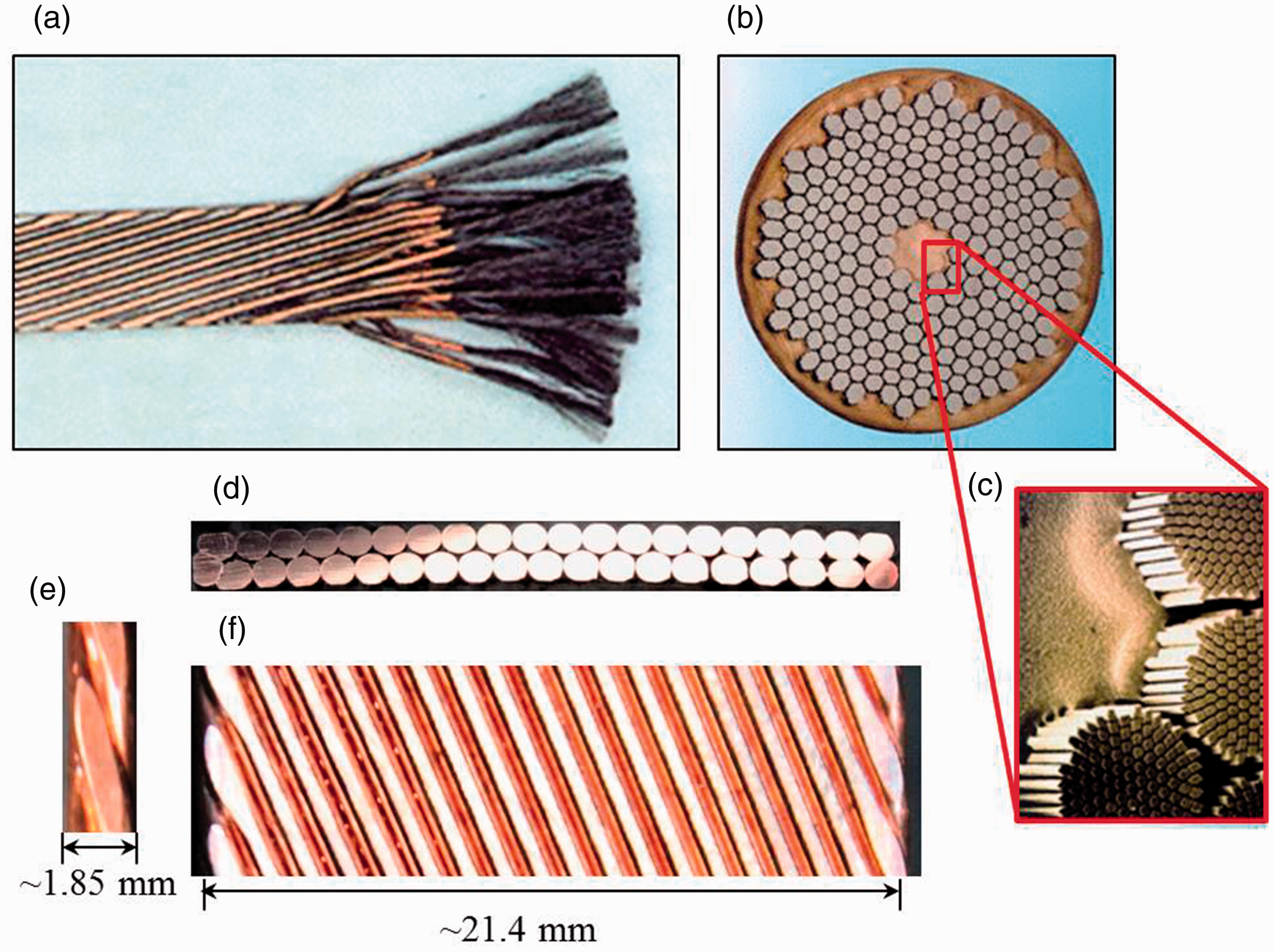
Superconducting dipole magnets used for accelerators provide high and stable magnetic fields up to 15 tesla [11–13]. Such high magnetic field is not possible to achieve using conventional copper conductor electromagnets. However, as the superconducting phenomenon is achieved at very low temperature, the particle accelerator chambers are operated in cryogenic temperatures [6]. The magnets use NbTi and Nb3Sn filaments in a copper matrix strand of up to 1 mm diameter. These strands are then transposed to make a cable in the rope or braid structure. However, in order to reduce self-field losses in dipole magnets, the strands are formed into a flat Rutherford cable [7] (Figure 5(a)). Although niobium–tin (Nb3Sn) operates in higher critical magnetic field and temperature, it is weaker and more brittle than NbTi [7]. The ductility of NbTi facilitated easier and cheaper fabrication [3]. The individual filaments of NbTi in each strand are as thin as 6 × 10⁻³ mm [14] and each strand contains up to 6300 NbTi filaments. In order to achieve thermal stability of the high field magnet material, the superconducting strands are combined with a copper matrix. The role of the copper is to act as a stabiliser in the event of a quench, both thermally to conduct heat and electrically to conduct the high current. It prevents the superconductor meltdown due to local temperature rise as a result of increasing current [3].
The cables are turned multiple times to form a coil block (Figure 3(b)) placed in the desired shape (Figure 3(c)). The insulation is required between the turns hence it is called ‘turn-to-turn’. Another form of insulation requirement is turn to ground. In the following sections, the Rutherford cable insulation process discussed has been focused on turn-to-turn insulation only.

Review of the Rutherford cable insulation requirements
Insulation layer thickness
One of the commonly used methods of insulating the cables is use of epoxy resin. However, for high magnetic field superconducting magnets, the epoxy is preferred to be reinforced with high performance fibres. The high field conductors apply compressive forces in the range of mega Newton per meter length of magnet. Glass fibre fabric tape wrapping was a conventional method of reinforcement for such insulation. However, tape wrapping results in edge overlap that provides a thickness build-up that is not always suitable for achieving very thin layer insulation. Braiding was first recommended [13] as a potential cable insulation for reducing thickness as the process applies a single layer on the cable. Two-dimensional circular maypole [17] braiding is a unique way of producing a tubular substrate. Though the braid cross section is circular, nevertheless the braided sleeve takes the cross-sectional shape of the core. This flexibility of reshaping the cross section enables over-braiding of the Rutherford cable that has a relatively rectangular cross section making it a suitable alternative for fibre tape.
The requirements of the fibre component of the insulation include the need to have good radiation resistance, temperature resistance of around 700℃, reasonable cost, commercial availability and free of boron. S-glass (R-glass in Europe) has a higher recrystallisation temperature (∼750℃) than that of E-glass [12]. Although E-glass is an easily available commercial glass fibre, one of the constituents of the fibre is boron trioxide (B2O3) [18]. It acts as a fluxing agent and hence it reduces melting temperature of glass and also its presence can influence fibre–matrix de-bonding in composite [19]. Unlike E-glass, S-glass has no or a little boron component making it a suitable fibre for braided insulation [20].
Thickness of the insulation layer is an important parameter for magnet design. In order to develop insulation for a high field (15 T) superconducting dipole magnet, a set of key specifications was established [13] focusing the issues and limitations. In the review, authors prioritised the integrity of the insulation over electrical breakdown strength. For a standard fibreglass laminate (G10), the required breakdown voltage is 20–30 kV/mm. However, the 15T dipole magnet stores high energy density, hence the insulation integrity is also very important.

Equation (1) shows that engineering current density is inversely proportional to the total cross-sectional area, and hence a thin layer of insulation improves the current density as presented by Blackburn et al. [21]. However, the insulation needs to be able to withstand handling whilst winding the magnet. Hence, a thin layer risk insulation robustness that is required for the application. A 10% higher current density from a thinner insulation was indicated [13] to be less important than insulation robustness that enables high integrity manufacturing. Hence, an optimum thickness of 0.15–0.20 mm on each side of the cable or 0.3–0.4 mm turn-to-turn was the target to achieve by using braiding process.
Review of the organic size substitute for glass fibre insulation
The superconducting cables are required to perform at high and very low temperature. Hence, improved strength retention properties of the insulation at varying temperatures became essential to avoid breakdown due to thermal expansion or contraction. S-glass fibre-reinforced composite became a choice to achieve the required mechanical properties. However, the commercially available glass fibre roving is coated with organic sizing materials to withstand abrasion and evade fibre damage. Fibre damage appears in the form of filamentation during the manufacturing process. Sizing application lubricates the filaments to reduce friction between the roving and machine parts and also improve the antistatic properties.
The glass fibre roving with organic sizing material is unsuitable for the insulation application. The cables are heat-treated at high temperature (650–700℃) [13,22] for about seven days [13]. The heat treatment is carried out in vacuum or in presence of an inert gas [23] (argon) to avoid oxidation of the cable surface [22]. Due to the absence of oxygen, the organic sizing on the glass fibre roving leaves carbon residue (Figure 4(b)) that decreases the dielectric strength of the superconducting cable. Hence, it is necessary to remove the organic size before the resin impregnation.
Organic size-coated glass fibre woven tape (a) before heat treatment (as received), (b) carbon residue from burnt organic components on the glass fibre tape after heat treatment at 660℃ in vacuum and (c) graph representing TGA analysis of HYBON 2001 E glass fibre as received (AR) and after desizing in air and inert atmosphere. (a) Rutherford cable with 36 strands used in LHC [14], (b) A single strand cross-sectional view that contains 6300 NbTi filaments [14], (c) NbTi filaments (0.006 mm thick) in copper matrix [14]. (d) Images of 40 strand copper cable used for braiding cross-sectional view. (e) Side view of the cable. (f) Top view of the cable (Wc).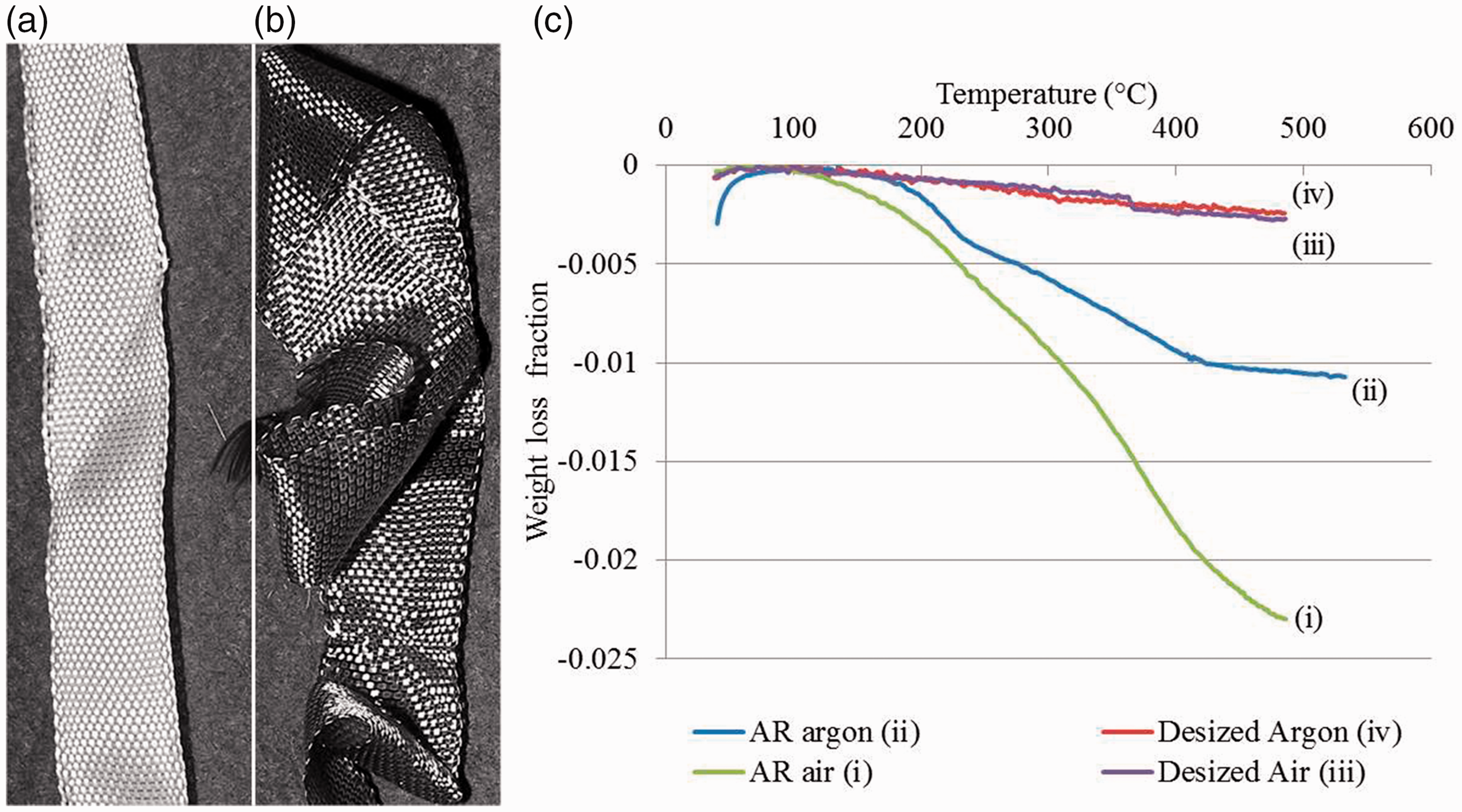
In order to use size-free fibre for insulation, two previous studies [13,20] followed two different manufacturing approaches. One of these studies [20] de-sized the material and re-sized it before use and another study [13] eliminated the use of organic size on the fabric tape with inorganic type. In the first study [20], commercially applied conventional size was removed from a S-glass woven tape (0.1 mm thick) developed by JPS. Re-sizing was carried out to provide minimum level of robustness for winding purpose. A small amount of high temperature size was applied to the tape that degraded during heat treatment to provide a light grey appearance. The laminated insulation provided sufficient electrical breakdown strength of 15 kV/mm [20].
In the other manufacturing approach [13], the organic size was replaced by an inorganic (ceramic) precursor with the aim of eliminating the resin impregnation step. Although heat treatment for superconductor provided robust ceramic insulation, it was a porous structure that allowed penetration of the liquid helium [13]. This is desirable from a thermal stability point of view. A glass fibre tape impregnated in the ceramic precursor was wrapped around the cable for insulation [13]. In contrast, helium porosity is not feasible for epoxy impregnated insulation.
If the fibre de-sizing before cable insulation is the preferred manufacturing route, several other studies [11, 12, 22, 24] suggested a fatty acid (palmitic) as a re-sizing material. The high boiling point of palmitic acid (∼350℃) made it a suitable material to be used for high temperature treatment of the superconducting cables. However, traces of carbon remained in glass fibre insulation layer [12] after the high temperature heat treatment had been carried out in an inert (argon) environment. Although one of the studies [24] presented that little traces of carbon were not detrimental to the insulation. Inorganic size chromium oxide was also used in one of the studies [12]; however, as a side effect the size led to the corrosion of the metal parts of the weaving machine. Another alternative to organic size was found to be polyimide (PI) [23] that was a relatively thermally stable polymer because of its highly aromatic chemical structure. The study [23] presented that PI re-sized S-glass insulation provided improved tensile and shear properties along with electrical breakdown voltage.
Braiding of Rutherford cables
De-sizing of glass fibre
The two major methods of removal of size from the glass fibre are dissolving the size and graphitisation in air. Because of the unavailability of the sizing composition, dissolving the size was not a suitable method. In contrast, high temperature burning out of size ensures removal of organic binders. A cheese of E-glass fibre was heat cleaned inside a large furnace at 350℃ to burn off the added size. There was visible colour change indicating size burn off from the fibre.
A Thermo-Gravimetric Analysis (TGA) of the fibre was carried out at RAL. The TGA essentially comprises of a very precise balance with the sample hanging in a furnace. This method is used to measure changes in mass with respect to temperature. Figure 4(c) shows the results from the TGA of the E-glass. The ‘As Received’ (AR) E-glass had a sizing, and when this was heated in air the sizing could combust and be fully removed. When the as received E-glass was heat-treated in argon as the atmosphere was inert the organic sizing could not be burnt off and fully removed. The size degraded to carbon and the E-glass sample weight decreased by 1%. Later the desized E-glass was put in the TGA and there was very little weight loss either in air or in argon. This indicates that the heat cleaning removed the most size from the fibre. It was suggested that a weight change at a temperature higher than 350℃ would indicate that the heat cleaning temperature was too low for maximum possible weight loss. However, as it appears in Figure 4(c), at 350℃ the as received glass fibre had a weight loss of ∼1.40% in air environment. The fibre datasheet [25] suggests that the fibre has a Silane size content of 0.55 ± 0.15%. This indicates that quoted amount of size was completely removed from the fibre.
Braiding preparation and Rutherford cable specification
Cable specification.

The cable was cut to produce small length of samples after braiding using a wire cutter. As the cable is a bundle of multiple strands (also known as wires), it usually left the cut section deformed with sharp edges. A section of the cable was set in resin before cutting and polishing to take the cross-sectional view of the cable to prevent any deformation. Although the cable appears to be flat and rectangular, the image of the cross section (Figure 5(d)) of the cable shows the width wise curvature of the cable. However, as the braided cables were placed in a stack and pressure was applied during resin infusion, the applied pressure would minimize the width wise bend.
Braiding using desized glass fibre
Desizing of the glass fibre roving decreased the fibre abrasion resistance thus reducing the processability of the roving. Without resizing, braiding was attempted using the desized fibre and filament breakage was observed during braiding and bobbin winding. Filament entangling was also increased that is also known as filamentation (Figure 6(a)) creating a ‘fibrous web’. Gradual increase in filamentation subsequently reduced the cross-sectional area of the roving that led to roving breakage during the braiding process. During bobbin winding, the breakage was reduced by reducing both applied tension and winding speed. Reduced number of broken ends on the bobbins reduced the filament entangling during braiding. An electronic atomizer (Figure 6(d)) was used to spray a stream of fine mist of water to the fibres in the convergence zone. Spraying water mist tends to provide adhesion between filaments within the roving as well as lubricate the roving to carry out the braiding process. Typical sizing includes an anti-static agent that was also removed during desizing. Hence, water particles allowed dissipation of static electricity along the fibre surface as glass fibre is non-conductive. With the aid of atomizer, two small length samples of braided cable were produced as braid angle consistency was not possible to maintain due to the roving breakage after short length of braiding. Similar observation was found by a previous study [20] in which desized glass fibre tape was found to be susceptible to damage during automated winding.
Braiding Rutherford cable using desized glass fibre: (a) filamentation and fibre breakage during braiding; (b) cable braided with the aid of atomizer; (c) insufficient cable coverage due to the lower braid angle and (d) atomizer spraying fine mist of water to aid the braiding process.
In order to make the heat cleaned glass roving functional for braiding, different coatings were applied. Water soluble poly vinyl alcohol (PVA) and epoxy were coated onto the roving and these coatings provided adequate binding of the fibres in the roving which would require a washing off the size with water after the braiding. In case of Silane sized glass fibre, the size works as a water repellent coupling agent and water adsorption may degrade composite mechanical properties by affecting the interface of the resin and fibre [26]. Hence, PVA and epoxy coating was later avoided to prevent washing off the size from braid.
Ethylene glycol, widely used as an antifreeze, is used as an anti-static agent for textile sizing. It was also used for re-sizing the de-sized glass fibre roving. It has a boiling point of 195℃ so it can be removed during the heat treatment. However, roving breakage appeared to be a setback during the coating process as the roving had to pass several guides and around the large circumference dryer cylinder. Reducing the number of guides the process was replicated and the coating was completed successfully with minimum filament breakage. Ethylene glycol-coated glass fibre roving was used for braiding and the roving breakage was reduced significantly. However, to avoid the total process of removal and addition of sizing, the manufacturing route was replaced by choosing a glass fibre with compatible size.
S-2 glass fibre braiding for insulation
Since there were difficulties in re-sizing the E-glass fibre roving, a compatible size coated S-2 glass yarn was acquired for the braiding purpose. The linear density of this yarn is 66 tex and the filament diameter is 9 µm. The glass fibre yarn had a sizing (933 size, AGY, Huntingdon, USA) that is stable at 350℃ and above and compatible with epoxy resin system [27].
Thickness and coverage data for the cable insulation using 300 tex E-glass fibre.

As the S-2 glass fibre had a lower yarn width and linear density, in order to achieve sufficient surface coverage, a 48 carrier braiding machine (Figure 7) was used for over-braiding the cables with a regular braid. Although the surface coverage was observed to be varying across the width (discussed in ‘Variations in surface coverage across the cable width’), the required braid thickness on each side of the cable (0.20 mm) was achieved. Several samples were produced with different braid angles for comparative study.
Braiding using S-2 glass with compatible size that provided optimum thickness with no major fibre damage.
Thickness and coverage data for the cable insulation using 66 tex S-2 glass fibre.

Analysis of braid parameters
Braid thickness and surface coverage
The thickness of the braided layer on the cable was measured using a micrometre. By using both flat/flat jaws of a micrometre, over-braided cable thickness was measured. The braid insulation thickness (tb) was calculated using equation (2) where tc is the Rutherford cable thickness and ti is the over-braided cable thickness on the width of the cable.

As the braid angles were changed in different samples, the surface coverage of the cable specimens was different (Figure 8). Cover factor (CF) indicates the extent of surface coverage by a fabric or braid when placed onto a tool. For a circular cross-section core, CF of a biaxial braid structure can be calculated using the following formula [29] where Wy is the yarn width, Nc is the total number of carriers, R is the effective radius of the over-braided core and α is the braid angle.
Braid cover variation on the cable: (a) Partially uncovered regions on the cable (top view); (b) cable surface mostly covered by braid (top view) and (c) fully covered surface of the cable (side view).

Since the cable cross section resembles a rectangular cross section (Figure 5(d)), equation (3) was modified to equation (4) to calculate the cover factor. In equation (4), ‘t’ and ‘W’ are the effective thickness and the effective width of the over-braided cable, respectively.

Effective thickness (t) and width (W) of the cable with the over-braided insulation layer can be expressed using equations (5) and (6) where 

The CF prediction using equations (3) and (4) considers that the braid parameters such as the yarn width, spacing, and braid angle are uniform around the circumference. However, as the cable cross section has unequal length of sides, the narrower sides had 100% surface coverage unlike the wider sides. This observation supports the findings of Van Ravenhorst and Akkerman [30] in which variation of braid angle was reported on mandrel with unequal sides. Hence, in this study, instead of averaging the braid angle of all sides, only the wider side (across the cable width) parameters were considered. However, this variation can be improved if required for future investigation by setting a ‘creating ellipse’ as proposed by Nishimoto et al. [31]. In order to get an approximate coverage from actual braid sample, the surface coverage was measured by means of image analysis. A Java-based program aimed for image processing called ImageJ, developed by the National Institutes of Health (USA), was used for the study of surface coverage on the wider side of the cable.
The braided cable samples were scanned with a ruler next to these (Figure 9(a)) by using a flatbed scanner to acquire the images those were used for analysis. By using the length from the ruler, the image dimension was calibrated. After the calibration, the image was cropped to separate the ‘region of interest’ that required analysis. The cropped image was then sharpened to detect the outline of uncovered areas and the image was changed to grayscale. Once the threshold option was activated, by default the fibre-covered areas of the braid layer were separated. As the uncovered areas were small, in order to focus on the uncovered area for analysis, the covered area was changed to a light background (Figure 9(c)). At this stage, the image thresholds selects the areas uncovered; however, it also includes parts of the cable edge with full surface coverage as uncovered. A possible reason for such segmentation is the image quality. The scanned image is a two-dimensional representation of a three-dimensional surface of the braid. During the image processing, the shades on the image were observed from sections segmented as uncovered surface. The threshold option shows a histogram that distributes the pixel intensities in the image. By moving the ‘slider bar’, those regions that were selected as uncovered and highlighted in red colour can be changed. The histogram was changed to deselect the edge area of the cable for individual braids based on the fully covered surface appearance. By using the software tool, the uncovered segmented area percentage was measured. This method was an approximate representation of the surface coverage from the actual braid parameters.
(a) Scanned image of the over-braided cable with a ruler placed next to it for dimension calibration. (b) Grayscale image of the cropped area for coverage analysis. (c) Separating the visible fibres from the uncovered surface area (appears in red) by applying threshold on the grayscale image. (d) Software windows indicating the tools and the results of the analysis.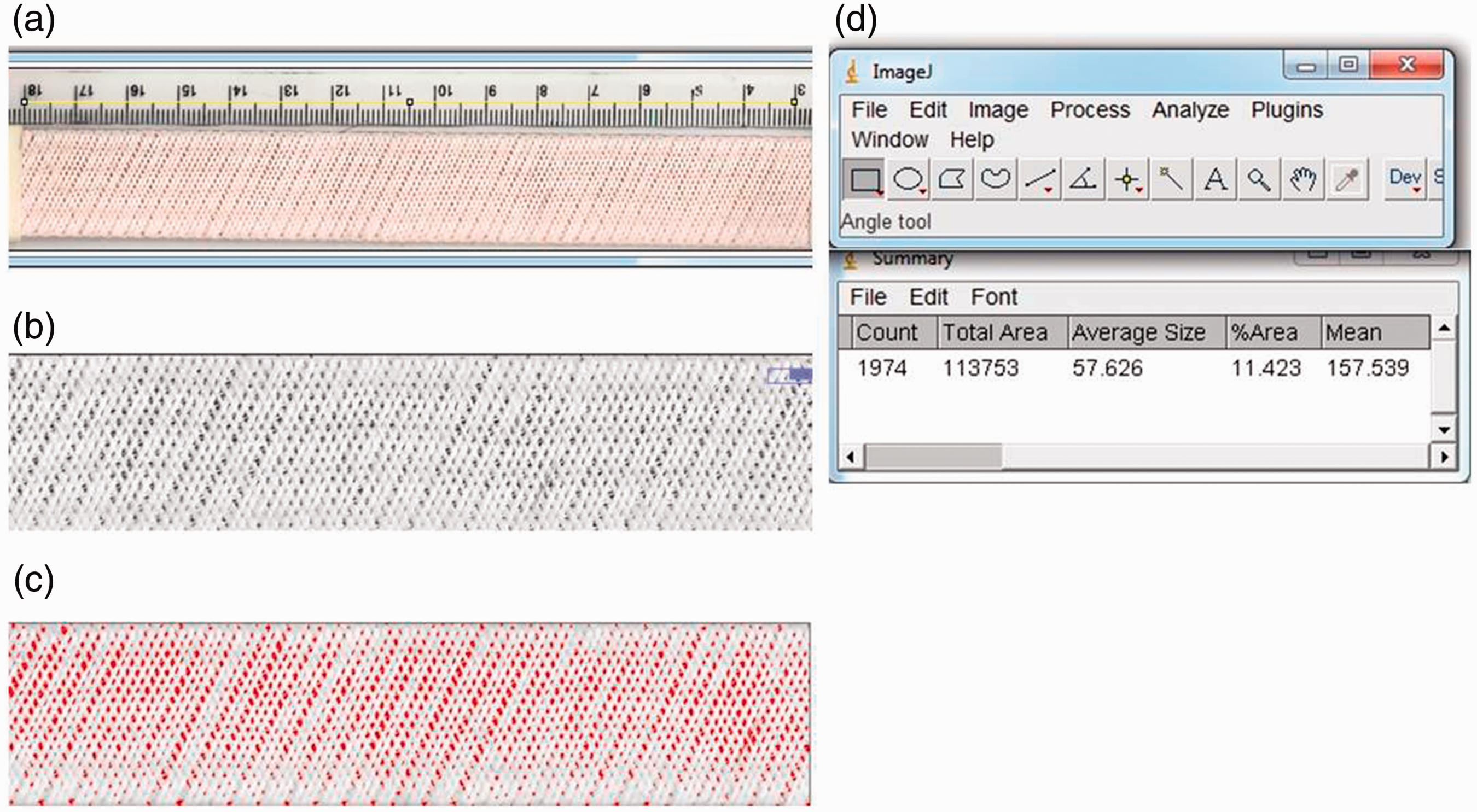
The braid parameters were measured from the wider side only to calculate the cover by using equation (4), so the data presented in the Tables 2 and 3 were comparable to the image analysis of wider side only. The braid thickness on wider side had an increasing pattern with the increase in braid angle for both E-glass roving and S-2 glass yarn. By using E-glass, the desired braid thickness for insulation (about 0.20 mm) was achieved with lower braid angle compared to S-2 glass as the E-glass linear density was higher than S-2 glass.
While braiding with S-2 glass, the optimum braid thickness (∼0.20 mm) was achieved at ±74.8° braid angle. However, over-braiding with higher and lower angles than ±74.8° was also carried out. During braiding of ±80.3°, higher filamentation was observed due to the fibre–to-fibre abrasion. Further testing of electrical breakdown will be carried out with braid thickness lower and higher than optimum.
Variation in surface coverage across the cable width
The comparative surface coverage from prediction and image analysis is presented in Figure 10. The difference in measuring surface coverage is higher for lower angle due to the braid parameter variation around the structure. For this study, as the cables were flat, a scanned image of the braid was in one plane that aided the image analysis. The maximum difference of surface coverage between the prediction and the image analysis was 7.8%. This indicates that the percentage of error is likely to be higher from prediction method because of considering the average values of individual parameters.
Comparative surface coverage of 66tex braid on the Rutherford cable estimated and measured using image analysis tool ImageJ.
As appears in the bar chart, the CF calculated using the modified equation had higher deviation from image analysis. Although average values of the parameters were used for calculation, a close observation on the over-braided cables showed variation in surface coverage within the wider side of the cable. It was apparent from the close observation that the surface coverage was higher on both edges of the wider side of the cable than that at the middle.
Equation (4) can predict CF closer to the actual for a braided structure with uniform yarn width and braid angle around the circumference. Hence the predicted coverage value had error compared to that from the image analysis. Based on the apparent cover variation, the braid on the cable was clustered (Figure 11(a)) in three sections – the two edges and the intermediate. Figure 11(a) presents the 22 mm wide over-braided Rutherford cable and full surface coverage was observed on both edges. About 15 mm wide section at the centre of the cable had ∼94.5% surface coverage illustrating the apparent variation in cover.
(a) Braid coverage variation across the cable width for ∼68.4° braid angle (sample W51) with 94.5% coverage across 15 mm width at the cable centre and ∼100% coverage over ∼3.5 mm width at both edge. (b) Braid cover variation due to different braid angle across the width of the cable.
By using the ImageJ software, the intermediate section was cropped and the cover percentage was analysed. As the braid angle was increased, the width of the intermediate section with less than 100% surface coverage decreased simultaneously increasing the fully covered width on both edges. By taking the width measurements of these sections, the surface cover variation is presented in Figure 11(b).
Discussion and conclusion
Over-braiding of Rutherford cable with glass yarn was attempted to create an insulation layer with stringent technical requirements – thickness of the insulation layer. The required layer thickness was 0.20 mm in order to achieve the desired robustness and sufficient breakdown voltage of the superconducting magnets. At the same time, thicker insulation layer results in lower current density that results in inefficient magnetic field. Initial braiding trials with E-glass roving were satisfactory; however, Silane sizing left carbon deposits during heat treatment of the cable. Desizing Silane and subsequent sizing with PVA created suitable insulation layer, but the thickness was less than optimum. Subsequently, changing from 300 tex E-glass to 66 tex S-2 glass required switching the braiding machine from 24 to 48 carriers to achieve the desired coverage. The finer S-2 glass ensured desired thickness and surface coverage. Higher braid angle was required by using 66 tex yarn to achieve the desired thickness compared to lower braid angle with 300 tex roving.
Since the cable had a resembling rectangular cross section, the braid structure around the mandrel had difference in parameters. This had an effect on the surface coverage on the width of the cable. The surface cover variation across the cable's width was observed between the braid angle ±65° and ±75°. With braid angles outside that range, the cover was more uniform across the width. As the cover factor depends on the braid parameters, this range will vary with a different type of fibres. Finally, upon completion of composite manufacturing, the electrical breakdown requirement was successfully met. Braid structures with less than 100% surface coverage achieved thinner insulation. Despite less coverage and thinner insulation layer, the minimum breakdown voltage was achieved for suitable development of superconducting magnets.
Footnotes
Acknowledgements
The authors would like to thank the Rutherford Appleton Laboratory operated by Science and Technology Facilities Council (STFC) for providing the materials for this research. They also wish to thank Mr Roy Gidley for arranging the glass fibre desizing at Fothergill Engineered Fabrics Ltd and Dr Vivek Koncherry for providing help in re-sizing the material.
Declaration of Conflicting Interests
The author(s) declared no potential conflicts of interest with respect to the research, authorship, and/or publication of this article.
Funding
The author(s) received no financial support for the research, authorship, and/or publication of this article.