
Abstract
Shortcomings in large deformation calculations by mesh-based numerical methods have been overcome by smoothed particle hydrodynamics method, which is a new meshless algorithm based on Lagrange description and has been widely used in simulations as blasting and impacting, but not been applied in research of engineered fabrics yet. In this paper, a fluid structure interaction method coupling smoothed particle hydrodynamics and finite element was proposed, by which the inflating process of a model parachute was investigated. In the modeling of parachute, the same nodes were shared by beam elements of reinforced belts and adjacent canopy elements to simulate the elastic constraints, while the parachute meshes model was adjusted to satisfy requirement of fluid structure interaction calculation by loading internal pressure, and surrounding flow field was described by smoothed particle hydrodynamics particles. Then, the fluid structure interaction calculating could be realized by contacting algorithm between particles and mesh nodes. The dynamic processes of expanding structure and flow field were obtained by this method. According to the analysis of numerical results, the parachute inflating process could be divided into pre-inflating stage, fully inflating stage and inflated stage; moreover, the noise occurred in wind tunnel experiment could be explained by this method. The “breathing” phenomenon and top collapsing of canopy appeared in numerical results, as corresponded to the tunnel experiment. This new method could be a good supplement in parachute design and research.
Keywords
Introduction
Parachutes are widely used in aviation lifesaving, aerospace recovery and other fields because of their light weight, easy folding and high reliability. Parachute inflating process is always a hot topic in aviation life support research, as whether the parachute could inflate and deploy with preset instructions will directly affect the safety of personnel or system. The investigation approaches are mainly divided into experimental and numerical, in general. The experiments, such as airdropping and wind tunnel test [1], cost huge manpower, material and financial resources, while the data are hard to collect and mechanism of expanding failure is difficult to reveal. The numerical analysis with advantages of economy and repeatability has become an important approach in parachute design and research.
Many different models or algorithms have been proposed for inflating investigation [2–10]. Purvis [2] used simplified canopy structure and flow field model to simulate a two-dimensional parachute inflating. Tezduyar et al. [3] and Stein et al. [4] realized parachute opening by deforming spatial domain/stabilized space time) method. Immersed boundary method was used by Kim and Peskin [5] to calculate single parachute and parachute cluster inflating, but only in low Reynolds number. Tutt and coworkers [6, 7] and Cheng et al. [8] investigated the parachute opening process by ALE (Arbitrary Eulerian–Lagrangian) method. Takizawa et al. [9, 10] applied SSTFSI (stabilized space time fluid structure interaction) method in work phase calculation of fully expanded parachute. These methods or models provide some useful references for new investigation. However, it could be found clearly that most works were based on weak coupling technology, as the coupling information could not exchange at one time step, and the inertia forces of fluid were ignored in structure calculation. The technology of weak coupling was difficult to calculate the complete process of inflating. Therefore, a good pre-inflated shape was used in most works to avoid errors caused by weak coupling. Although the ALE method could avoid this, a large part of calculation time would be consumed on distortion meshes processing and flow field information updating. Besides, all previous methods were carried on the mesh-based model, which could only describe continuous medium as air and water, but not the medium discrete in macroscopic and continuous in mesoscopic, such as rain, hail and snow. Therefore, the parachute inflating under crucial environment could not be calculated by previous methods.
The SPH (smoothed particle hydrodynamics) method as one of meshless numerical methods has advantages that traditional mesh-based models do not have. The adaption of SPH approximation method prevents the randomness of particles distribution from affecting the formula, which could be used to deal some large deformation problems. With continuous improvement and modification, the accuracy and stability of SPH have satisfied requirements of engineering application [11]. This meshless method with wide application range could be applied in different scales of discrete or continuous systems, such as fluid motion, large deformation and impact problems [12–15], as it has become an important approach in numerical investigation.
The parachute inflating is a typical FSI problem with material and geometric nonlinearity, as all expanding process of inflatable fabric. Under Lagrangian description, the air has large displacement and deformation during interaction, which SPH method was good at solving. Therefore, the canopy was described by finite elements (FEs) and air flow by SPH particles in this paper. As both the FEs and particles were based on Lagrangian description, the FSI problem could be transformed into a contact problem of different materials. In this paper, the inflating process of a model parachute was calculated by the method above. The dynamic processes of structure and flow field were obtained.
Mathematical model
Fundamental theory of SPH
In the SPH method, the approximation

And the kernel weight function


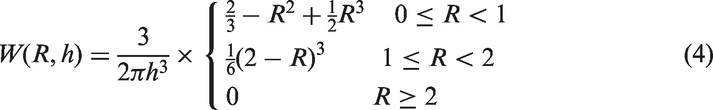
There are lots of kernel weight functions satisfying conditions (3), among which the function based on cubic B-spline proposed by Monaghan is the most widely used one [11] that was used to construct the governing equations here. The three-dimensional expression is as follows
Therefore, the integral approximation (equation (2)) could be transformed to the sum of all the particles in support domain, and the discrete form is as follows

Therefore, the derivative function of equation (5) was given by

Governing and discretization equations
The governing functions could be expressed by equations (7) to (9). The Greek alphabet α and β denote directions. The variable with superscript α or β is vector while the one with


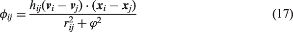
In the Newtonian fluid, the viscous shearing stress 
Based on equations (5) and (6), the expressions of governing equations used in SPH algorithm were


Here,


Coupled SPH particles with FE nodes
FE model was applied by most researchers to describe inflatable fabrics, as it not only can reflect the mechanical properties but also the dynamic simulation can be achieved. In addition, this algorithm with high calculates precision can be integrated with other system model [16]. Therefore, the FE model was used to simulate parachute in this paper.
With Lagrangian description of fabrics and air, the FSI problem here can be treated as a contact problem between two materials. The penalty function algorithm was used to realize the coupling, as widely applied in many well-known explicit dynamics codes since this method was easy to program and accurate in momentum conservation.
The SPH particles were defined as slave nodes, while the nodes of canopy elements were as master ones (Figure 1).
The projection relationship between canopy elements and SPH particles (here,
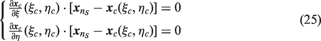
In each time step, the nearest master node ms of each slave node ns was searched. The element contacted with slave node ns was chosen by


If the slave node

The spatial coordinates of contact point C was defined as

Then, the reference element coordinates The position of contact point C under reference element coordinates.
The penetration of SPH particle through the canopy element was judged by

The SPH particle has penetrated through the canopy element (if

The whole coupling calculation process is shown in Figure 3. Two methods were carried separately at the same time. The SPH method was applied with Leapfrog (LF) scheme [11] in time marching, and the FE method was applied with central difference scheme [17].
The coupling calculation process.
Case study
A flat circular parachute without material permeability was used to investigate. The flattened canopy structure is shown in Figure 4. The whole canopy was sewed by eight single gores. The nominal area of this model parachute was 0.78 m2, and each parachute line’s length was 0.75 m.
Flattened structure of model parachute.
Material and constitutive model
The canopy was made in 49201 type polyamide grid silk (Figure 5), the lines and reinforced belts were made in 3-250A flame-retardant polyamide rope and 10-200A type belt, respectively. The material parameters of fabrics and air are shown in Table 1.
The 49201 type polyamide grid silk. Material parameters.
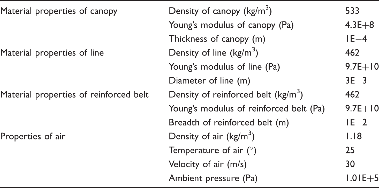
In this paper, the fabrics described by FEs were treated as continuum, and the mechanical properties of yarn layer were homogenized. Therefore, the lines and reinforced belts were described by one-dimensional linear elastic constitutive equation as follows

The canopy presents small strain and large rotation in parachute expanding, and a large deformation effect of structure is mainly resulted from the large rotation. Therefore, the Saint Venant Kirchhoff constitutive equation was used to describe the fabric, which had been widely used in parachute dynamic simulation [6–8]

Then, the Cauchy stress 
In addition, the canopy was discretized by three nodes shell elements, and the fabric material anisotropy was neglected in this paper. As a result, the constitutive equation (29) in Voigt matrix form was shown by

In this paper, the velocity of air was less than Mach 0.3, which means the air could be considered as incompressible material, and the stress description is divided into a deviatoric part and a hydrostatic part. The constitutive equation of air is shown in equation (32), which must be integrated with ideal gas state equation

Parachute model
The textile modeling was key and difficulty point in this paper, which was divided into three steps in this paper.
The canopy modeling
First, the canopy’s folded geometry model was established in sequence of points, lines and surfaces according to actual sizes (Figure 6(a)), on which, the mesh model was based. In general, the accuracy of the mesh model was higher based on quadrilateral elements than on triangular elements, and the quadrilateral elements were suitable to describe the model with a good pre-inflated shape and befitting in numerical calculation with implicit algorithm [2–5, 9, 10]. However, the triangular elements had better adaptability and were more suitable in solving of the large displacement and deformation problems [8]. In Figure 6, Model A was meshed by triangular elements (4656) and Model B by quadrilateral elements (4640). It was found that the Jacobian ratio of all triangular elements was greater than 0.8 in Model A, while only 77% elements’ Jacobian ratio was acceptable (greater than 0.8) in Model B. The elements of poor quality concentrated mainly on the canopy top, of which the modeling quality was very difficult to be improved by local trimming. The model with low Jacobian ratio was more likely to cause calculation instability and extend calculation time. Therefore, the Model A was used in this work.
The geometry model and mesh model: (a) geometry model; (b) Model A and (c) Model B. Here, the element which Jacobian ratio was less than 0.8 was highlighted by gray color. The Jacobian ratio could characterize the difference between the element’s actual and ideal shape and was usually used to evaluate the quality of meshes. The greater ratio, the better quality elements have.
The reinforced belt and lines modeling
In this paper, the lines and reinforced belts were meshed by beam elements (616). In order to simulate the elastic constraints generated from these belts accurately, each beam element shared the same nodes with adjacent triangular elements (Figure 7). This sharing ensured the canopy and reinforced belts have same deformation at same position. In fact the Young’s modulus of reinforced belts was larger than the canopy’s (Table 1), and therefore, the deformation of canopy was constrained by those belts in calculation. In Figure 8, a change in small area could be found in the canopy area with reinforced belts, due to the elastic constraints during inflating process. The engineering application that reinforced belts are used to prevent canopy rupture with large deformation was also verified.
The reinforced belt modeling: (a) the actual reinforced belt and (b) the corresponding model. The total area changes of canopy during parachute inflating.

Model adjustment
The SPH/FE coupling method did not need to establish complicated, body fitted meshes or define interaction surfaces, which was same in ALE method. The parachute elements and SPH particles were allowed to intersperse with each other. But there must reserve a few SPH particles inside folded canopy model to ensure the interaction with both sides of SPH particles was at the same time (similarly, inside of folded canopy model should reserve a few of flow field meshes in ALE method). Therefore, the folded parachute model obtained by the first two steps must be adjusted (Figure 9).
The relative position relationship of parachute model before adjustment and SPH particles (view from bottom).
In order to solve this problem, Tutt et al. [7] proposed the FH (free hanging) method. But that method could not guarantee the canopy was completely folded, and the inflation time would be affected greatly by the model obtained by FH method. In this paper, the Loading Pressure method was proposed. First, the connection point of parachute lines was fixed. Then, a small amount of pressure (1000 N) was applied on the inside surfaces of the canopy. The canopy deformation process under the internal pressure was obtained by explicit calculation (Figure 10). At 0.04 s, the parachute model could satisfy the requirement of coupling calculation and be exported, and the explicit calculation was terminated (Figure 11).
The deformation process of parachute model. The relative position relationship of parachute model after adjustment and SPH particles (view from bottom).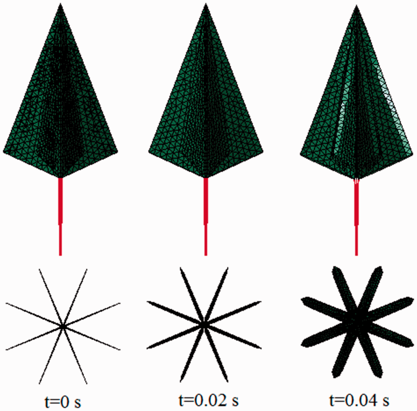

Flow field model
Since the air was simulated by SPH particles, and the velocity boundary could not be defined as finite volume method, the flow field was taken as a reference in this paper, other than the parachute as a reference in wind tunnel experiment. The relative motion of parachute was defined to simulate the parachute opening in wind tunnel. SPH particles (1,458,000) were used to describe the air flow field. The flow field boundary was defined symmetrical (Figure 12(a)). The velocity condition was applied on the collection point of parachute lines. The parachute elements and SPH particles were allowed to intersperse with each other, as the whole model was shown in Figure 12(b).
The elements and SPH particles model: (a) air flow field and (b) the whole model.
Wind tunnel experiment in Yu’s work
The corresponding wind tunnel experiment investigation was carried on in a low-speed wind tunnel with the diameter of 2.5 m [18]. The experimental apparatus are shown in Figure 13. A high-speed camera was set in front of the wind tunnel, with its image data were received and stored in computer, and an electric control system was used to trigger the dowel and collect the data.
The wind tunnel experimental apparatus in Yu’s work [18]: (a) schematic figure and (b) local magnification figure.
In this wind tunnel experiment, the canopy top and guiding parachute were connected with a line (Figure 13(b)), while the lines connection point and parachute box were also connected. Then, the model parachute was folded according to standard requirements and stored in the parachute box sealed by package cloth.
When the velocity of blowing air from wind tunnel was stable, the experiment countdown began. Once it started, the electric control system pulled out the dowel, and then the model parachute would be pulled out by the guiding out of the parachute box. Meanwhile the high-speed camera recorded images and sent them to the computer.
Results and discussion
Analysis of numerical results
The changes of shape and velocity vector are shown in Figure 14.
The dynamic change of shape and flow field over time in numerical results: (a)-(e) represent 20 ms, 45 ms, 55 ms, 75 ms and 113 ms respectively (under the airflow velocity condition of 30 m/s).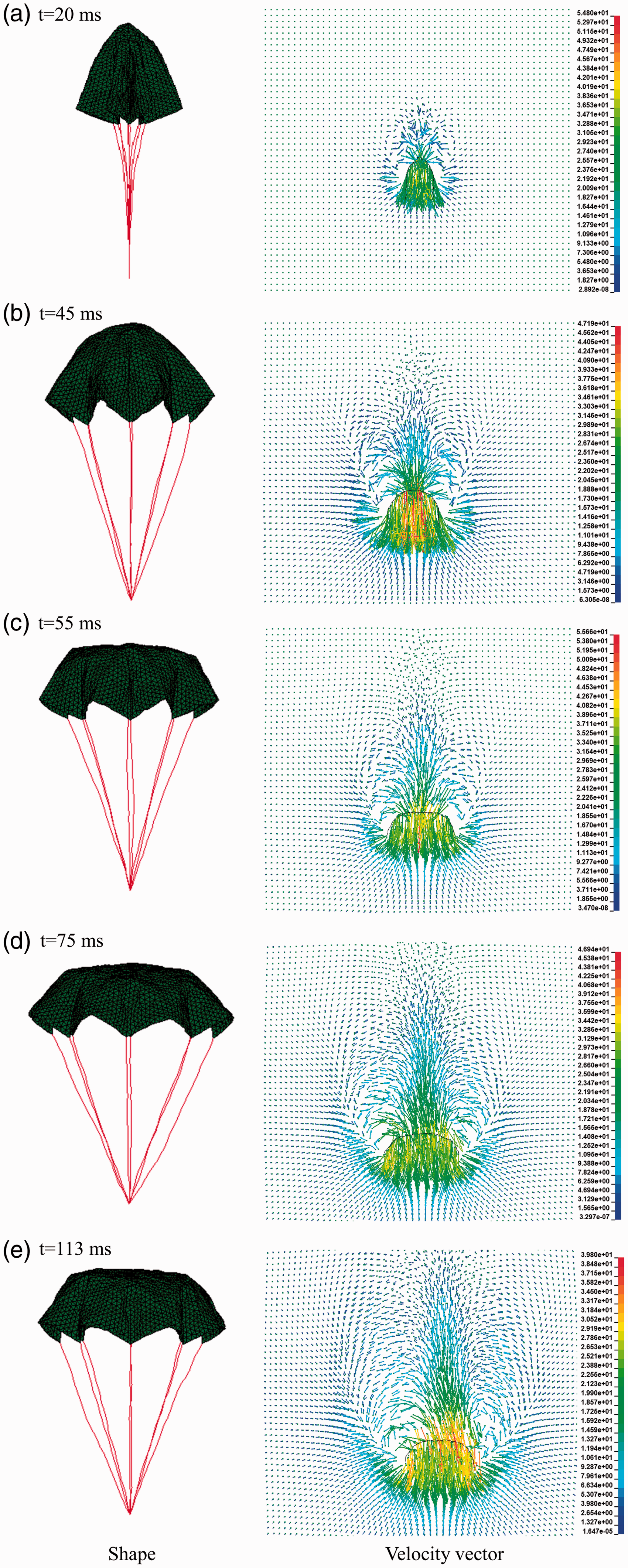
According to the changes of canopy shape and flow field, as shown in Figure 14, the inflating process of model parachute could be divided into pre-inflating stage, fully inflating stage and inflated stage.
The pre-inflating stage (0–45 ms)
First, the canopy bottom began to expand, and then the canopy top began to expand (Figure 14(a)) as the airflow entered into the canopy. Meanwhile, the canopy bottom easily formed edge curling due to the lack of effective constraints, which would exacerbate the instability of flow field. The canopy top was fully expanded at 45 ms, which was marked as the end of pre-inflating stage.
The fully inflating stage (45–55 ms)
As there was no vent on canopy top, the fluid inside flew out faster. During this stage, symmetric vortex was forming in external flow field (Figure 14(b)), while the effective decelerating surface was forming with the canopy expanding gradually from top to bottom. The inflating was very soon due to the small parachute size. The fully inflating stage ended at 55 ms (Figure 14(c)).
The inflated stage (after 55 ms)
After the canopy was inflated, it continued to expand due to inertial force. And over-expanding would be stopped quickly under the elastic forces of the reinforced belts and lines, which also caused the collapse of canopy top. Then, the canopy formed the largest aerodynamic shape when projection diameter reached maximum value at 75 ms (Figure 14(d)). But the top collapse disappeared soon due to airflow. Subsequently, the “breathing” phenomenon occurred, and a stronger symmetric vortex in external flow field was found, which appeared strong and weak alternately later (Figure 14(e)). Under the canopy and airflow interaction, complicated changes of structure and the flow field were found near the canopy bottom, where constant flapping and jittering due to lack of effective constraints appeared, which explained the noise during wind tunnel experiment.
Comparison of numerical results and experimental results
In Yu’s work, the model parachute opening experiments at various velocities (20 m/s, 30 m/s and 40 m/s) were carried out. The comparison of projection diameter between numerical and experimental results is shown in Figure 15.
The comparison of projection diameter.
It was found that the greater the airflow velocity, the earlier the peak value of projection diameter appeared. The results indicated that shorter parachute inflating time and earlier peak value appearance could be obtained by increasing airflow velocity from wind tunnel. Almost all of the results in Figure 15 showed that the canopies would reach the maximum projection diameter only one time at the first peak. Then, the projection diameter changed alternately with “breathing” phenomenon of canopies.
Longer inflating time was found in experiment than in simulation. The initial inflation shape was considered as the main reason. An ideal and completely symmetry model was used in calculation (Figure 10), while the canopy shape was asymmetric before inflation in experiment. Besides, there was a deflection angle between the airflow direction and canopy’s central axis due to gravity when the canopy was pulled out of parachute box and began to inflate (Figure 16). The gravity was neglected in calculation, and thus, there was no deflection angle. Furthermore, mechanical vibration and turbulence intensity resulted in the asymmetric of canopy shape when it began to expand in wind tunnel. The error between the two results verified that the inflating time and altitude loss could be reduced by a good pre-inflation canopy shape.
The comparison of shape changes (under the airflow velocity condition of 30 m/s).
Figure 16 is the shape changes under the airflow velocity condition of 30 m/s. It was found that the shape changes were basically the same. After the canopies were inflated (the experimental: 245 ms; the numerical: 55 ms), top collapse and maximum projection diameter were found on both canopies (the experimental: 272 ms; the numerical: 75 ms). Then, the canopies restored to inflated shape under the elastic force of material. The comparison showed that the numerical method used in this paper could be a good simulation for the dynamic process of the parachute inflating.
Conclusions
As a meshless numerical algorithm, the SPH method has the advantage that the traditional mesh-based methods have not, and a very wide prospect of application. In this paper, the SPH/FE coupling method was used to simulate the dynamic process of a model parachute’s inflating. The conclusions are as follows:
The beam element shared the same nodes with adjacent elements, which could simulate the elastic constraints from reinforced belts effectively. The numerical results of different models also verified that the reinforced belts could effectively control the canopy deformation. The Loading Pressure method was proposed to adjust textile model, and this new method could ensure the folding of adjusted model was completed and would satisfy the requirement of FSI calculation. The SPH/FE coupling method could exchange the coupling information immediately at one time step by using contact algorithm, by which the fluid meshes reconstruction and flow field information updating could be avoided. It is completely a new method to investigate the working process of parachute numerically. After inflated, the canopy would appear top collapse and reach the maximum projection diameter for the first and only time. Then, “breathing” phenomenon of canopy occurred while constantly flapping and jittering of canopy bottom appeared, where effective constraints were lacking. That made the noise during wind tunnel experiment clear.
Footnotes
Acknowledgements
The investigations described in this paper are a part of the research project no. F2015KF03 realized at Civil Aviation Flight Technology and Flight Safety Research Base.
Declaration of Conflicting Interests
The author(s) declared no potential conflicts of interest with respect to the research, authorship, and/or publication of this article.
Funding
The author(s) received no financial support for the research, authorship, and/or publication of this article.