
Abstract
In order to model complicated folded fabric, this paper proposed a new reverse modeling method. Two kinds of concrete implementation were investigated, which were based on graphical deformation and nonlinear dynamics, respectively. The first method learned from Free-Form Deformation technology is used to form the regular folds, while the element distortion rises. The second method adopts a fluid structure interaction algorithm to form the irregular folds. Both methods can transform the finite element model from expanded state to initial folded state without changing the mesh topology. Therefore, the mapping relationship between the finite element models of expanded state and folded state can be naturally obtained. Then, the initial stress used to modify the model can be calculated according to the mapping relationship, and the modifying can ensure the accordance of inflated flexible fabric’s geometry and the original design. At last, the finite element model of an inflatable fabric, which cannot be modeled by exiting method, was established by the new reverse modeling method with its feasibility and accuracy verified by comparing the calculation results. The results of this study could provide a reference for modeling complicated folded fabric.
Keywords
Introduction
Flexible inflatable fabric with advantages of small storage space, low cost and high efficiency, is applied widely. The typical representatives of inflatable fabric, such as parachutes, Inflatable Aerodynamic Decelerators (IADs) and airbags, have irreplaceable roles in their respective fields. With the development of material technology, even some new types of inflatable fabric (e.g. inflatable antenna, flexible solar sail) with special use and shape trend to replace the original rigid structure or design [1–4]. However, the inflating and deploying of inflatable fabric are the most important and dangerous processes. They directly relate to the system or life safety, as to whether the deployment is successful or whether the folding pattern is reasonable. Many failed spacecraft recoveries have strongly associated with the deploying of folded parachute, and the incorrectly folded safety airbag of automobile can wound the crew instantly [5,6]. Therefore, the deployment of folded inflatable fabric gradually becomes a research hotspot.
In a historical look at inflatable fabric studies, the results of numerical studies are particularly prominent due to the rapid development of hardware and theory [2,4,5,7,8]. And most of these studies take the finite element model that differs from other models used in most woven fabric studies. Not only can the finite element model reflect the mechanical properties, but it also achieve the dynamic simulation. In addition, this model with high calculation precision can be integrated into other system model. Although the woven fabric studies based on finite element model focused mostly on mechanics analyzing at mesoscopic level or draping and buckling simulation at macroscopic level [9–13], the studies on folds modeling at macroscopic level are less. At present, the main folds modeling methods are Direct Folding Method (DFM) and Initial Metric Method (IMM). The DFM establishes the folds directly from bottom level to top, or achieves simple folding by transforming coordinates of partial elements [14], while the IMM is used to achieve folding of the simple geometry which cannot be flattened. As based on complex algorithms, the difficulty of IMM lies in establishing the mapping relationship between the reference meshes and mapping meshes. Therefore, the element types are limited and the quality of element is greatly affected by calculation parameters [15,16].
As the common feature of the two modeling methods above is that the initial folds must be established directly, and the node coordinates of wrinkles or folds must be determined during modeling, these exiting methods are only applicable to simple shape or simple folding pattern. However, a lot of new inflatable fabrics have complicated shape and folding pattern, where a large number of irregular folds or wrinkles exist under the folded state, which is very difficult to model by DFM or IMM. Now, the folds modeling technology restricts the numerical studies of inflatable fabric. Aiming at the key problem, this paper proposed the reverse modeling method.
Principle of reverse modeling
The core idea of the new method is explained briefly as follows: (a) Firstly, a fully expanded finite element model is established. (b) Then the Degrees of Freedom (DOFs) or displacements of constraint nodes are defined and the other free nodes displace by different algorithms, which can form the folds or wrinkles indirectly. Here, the algorithms used in this paper are Constrained Free-Form Deformation (CFFD) and Arbitrary Lagrangian-Eulerian (ALE), as the former is used to form regular folds while the other to form irregular folds and wrinkles. (c) At last, the initial stress is applied to modify the initial error caused by folding process.
Constrained Free-Form Deformation algorithm
At present, the CFFD technology, a free-form surface modeling method, is widely used in the design of industrial products, computer animation, and special effects. This algorithm provides the surface modeling by operating the points or lines without any medium. The key advantage is the higher accuracy of the new positions of all geometrical elements after deforming [17]. Here, in view of this surface modeling method, the reverse modeling based on graphical deformation was proposed in this paper.
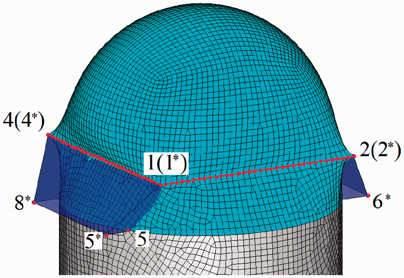
In Figure 1, the cyan elements are to be deformed, while the grey ones fixed. The point The constraint point and transformation area.
In the plane of triangle The constraint point and displacement of arbitrary points.
Arbitrary Lagrangian-Eulerian algorithm
The nonlinear dynamics based on finite element method is used to form the irregular folds and wrinkles. The mechanical boundary conditions are applied on the nodes in deformation area, while the external load would cause nodes displacement, which indirectly form the folds and wrinkles. Although various kinds of external load and loading mode exist, the fabric is very sensitive to the loading magnitude, duration, and direction. Therefore, the flow field force was employed as external load in this paper, and then the folding process would turn into Fluid Structure Interaction (FSI) calculation based on ALE algorithm.
Both the fluid and fabric material region are described in Lagrange mesh. The meshes deform with the material deformation, which ensure the mass conservation naturally. Therefore, only the momentum equation needs to be solved in the ALE algorithm [18,19].

The spatial discretization scheme of the momentum equation can be obtained according to the virtual work principle

Except for the spatial discretization, the folding process with large displacement and deformation should be discretized in time (Figure 3). Here, the central difference scheme, as most widely used in nonlinear dynamics [18], was used to discretize the semi discrete equation.
The time axis (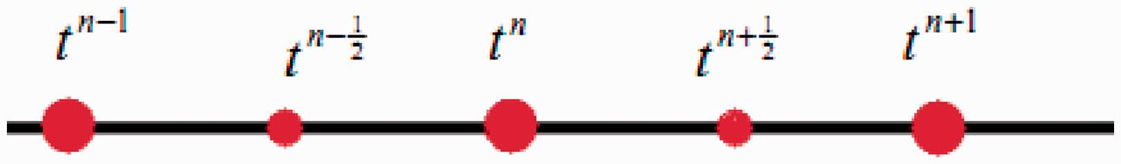

At each time step, the movements and deformation of elements used to described fabric or fluid are calculated by the discretization equations above, as these Lagrange elements deform with the material deformation. The Lagrange elements can accurately describe the nodes displacement, but in fact, the fluid material could not bear the shear stress and tension, thus the serious element distortion or negative volume was raised. Therefore, the elements used to describe the fluid must be restructured after each Lagrange calculation step, and the information of original elements should be transported to the updated elements (Figure 4).
The principle of ALE.
For simplifying the calculation, the flow field was fixed in this paper. After executing the Lagrange step, only the fluid elements are restructured. The nodes coordinates in physical domain can be obtained by solving the Laplace differential equation [20]
After the meshes restruction, the convection terms are updated based on Finite Volume Method (FVM), and its three-dimensional form is as follows
The discretization and solution of the convection equation (5) employed the Monotone Upwind Schemes for Conservation Laws (MUSCL) scheme [21] with second-order accuracy in this paper.
Principle of initial stress modification
The core idea of graphical transformation and matrix transformation comes from Computer Animation, and do not comply with any physical conservation laws. Therefore distorted elements would arise, and cause the discordance of shapes in inflated state and original design. So the element finite model based on this method must be modified.
The model with accurate appearance is taken as the reference meshes, and that model processed by matrix or graphical transformation is taken as the mapping meshes. Because no change of topological structure occurs during transforming, each node displacement The principle of initial stress modification.
To elaborate the modification method, a cylindrical fabric was taken as an example. In Figure 6, some distorted meshes appeared after graphical transforming. But the topological structure (such as the type, arrangement of elements) remains the same, which means the mapping relationship could be obtained naturally. The original model was defined as the reference meshes, while the deformed model was defined as the mapping meshes. The modification stress was calculated according to the mapping relationship and applied on the distorted meshes. At last, the geometric error was corrected.
The example of initial stress modification.
Figure 7 shows the element (the distorted element of No. 987 shown in Figure 6) area changes at various time when stress applied. It was found that the element areas after modification were 0.04 m2 which were same as the original area. The fluctuating of element area was due to numerical error. Therefore, the modification effect is independent of time, and the initial stress could apply on the mapping meshes at any time.
The element area change after modification.
Example
A special airbag with big length to diameter ratio is a core component part in some system [22,23], as the successful inflation and expansion of this airbag relate to the system safety directly. The airbag is composed of conical bottom, cylindrical middle, and hemispherical head, which is stacked like an accordion in practical engineering. Because of the existence of many regular or irregular folds and wrinkles, the amount of volume compression is very large. In order to simulate the inflating process of this airbag and to study the working characteristics, the modeling of such complicated folded airbag is the first difficulty. If using DFM, the modeling work needs calculation of the accurate position and interrelation of each fold, while the IMM needs establishment of a similar geometric model in folded state and mapping relationship, which is also a difficulty. Both DFM and IMM modeling are tedious, and even difficult to achieve.
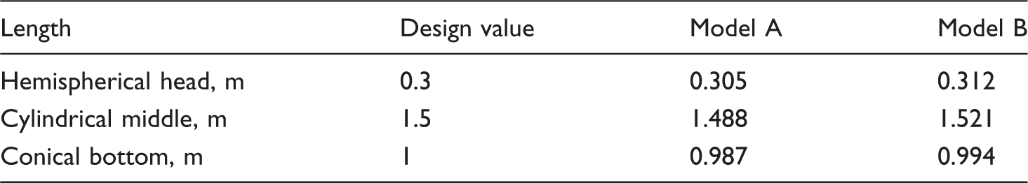
However, the reverse modeling method proposed in this paper can solve this key problem. In this method, the axial direction was defined as Z axis firstly. Then, the expanded geometry model was established according to the actual size and divided into several segments according to the actual position of crease lines. The triangular and quadrilateral meshes were used to divide the whole geometry model (Figure 8).
The geometry and finite element model in expanded state.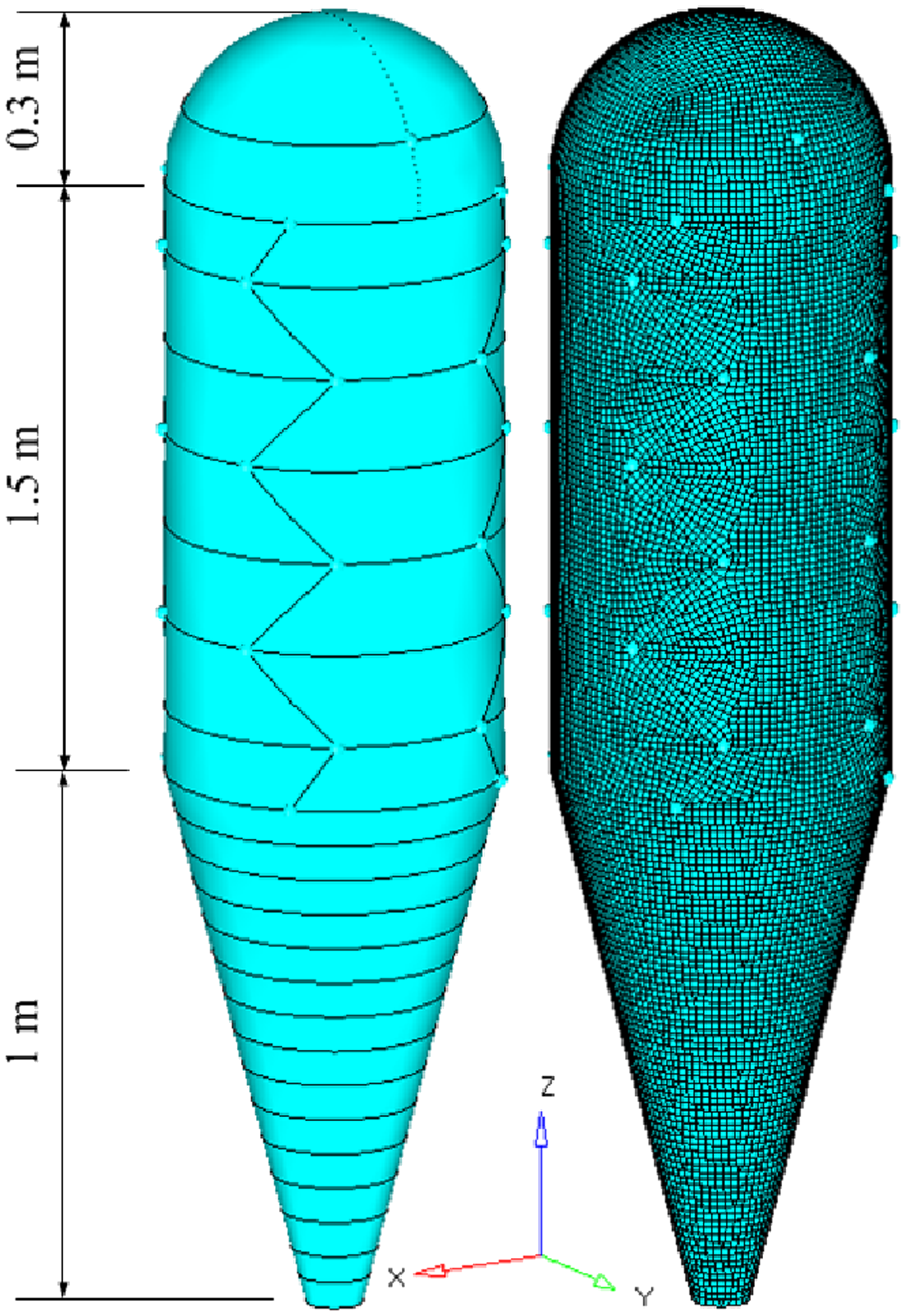
In order to establish the folded model, different methods were applied on modeling of different parts. The existing matrix transformation method was used to model the conical bottom, while the reverse methods based on CFFD and ALE algorithm were applied on middle and head, respectively. Finally, the initial stress was used to modify the error introduced by graphical transformation. In order to distinguish the correction effect, the modification was applied during numerical simulating.
Modeling based on matrix transformation
The existing method was used on conical bottom to achieve the folding. The three-dimensional node position was represented by a four-dimensional homogeneous coordinate

According to the actual requirements of folding, the elements below the crease line n were reflected about the plane

In Figure 9, the first crease line was in the plane The folding based on transformation matrix.
Modeling based on Constrained Free-Form Deformation
For accurately forming the regular folds in middle part, a series of constraint surfaces (light blue color) interspersed with elements (cyan color) were established firstly. Each constraint surface corresponded to a surface segment (Figure 10). Here the modeling of the first fold in middle part was taken as an example and would be elaborated in detail.
The position of constraint surfaces.
As shown in Figure 11, the elements in cyan region would be deformed, while grey elements fixed. The red nodes on arc The constrain points and projection line. The first transformation.
The transformation boundary and region were reset, as shown in Figure 13. By the same method, the nodes on arc The second transformation. The third transformation.

Other regular folds in middle part could be formed by the same process (Figure 15).
The modeling of the other folds.
The transformation matrix was used again to complete the middle part modeling (Figure 16). The centroid The finally folding of middle part based on transformation matrix.

Modeling based on Arbitrary Lagrangian-Eulerian
As the aim is to obtain a model with small strain, the material properties defined in calculation can be different from practical. In this paper, an ideal isotropic elastic material with high strength (Young’s modulus was 20 GPa, and Poisson’s rate was 0.14) was applied. In addition, the ALE algorithm need not establish body-fitted flow field mesh. The hexahedral meshes interpenetrated with the structural meshes were used to describe the flow field. The air flow blew the structural model from top to bottom (Figure 17).
The ALE model and boundary conditions.
The folding process of head part was calculated by ALE algorithm. While the middle and bottom parts in folded state were fixed, there was no coupling effect between fixed parts and field flow; in other words, the air would flow through the structural elements of fixed parts directly. Under force of flow field, the head part of airbag began to collapse and formed the irregular folds and wrinkles. When the head part was compressed to a certain height, the calculation was stopped (Figure 18).
The folding process based on ALE (velocity vector and strain contour).
In practical engineering, during whole system integration, the airbag usually needs to be assembled in a limited space; therefore, the finite element model was scaled down by a factor of 0.9 on X, Y, and Z directions. Finally, the folded airbag model was well matched with the system model, while the volume of airbag in folded state was compressed to 4% (Figure 19).
The final folded model.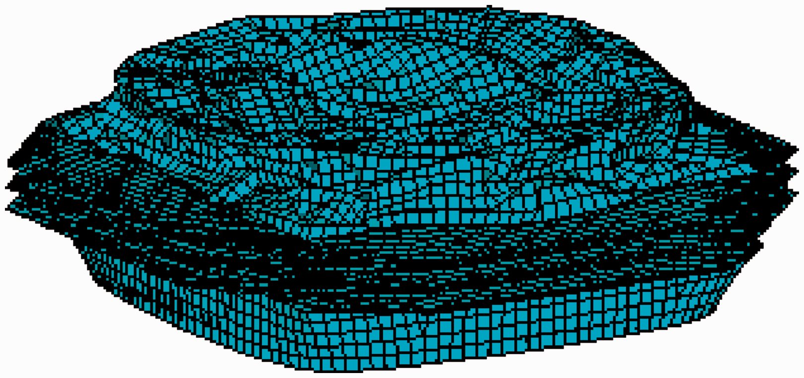
Results and discussion
In this paper, the inflation process of above folded model was simulated by Control Volume (CV) method [5]. The folded model without scaling transformation and modification was defined as Model A, while the scaled one shown in Figure 19, which is modified by the initial stress, was defined as Model B (here, the finite element model shown in Figure 8 was defined as reference meshes, while the model shown in Figure 19 was the mapping meshes). With the purpose of distinguishing the modification effect clearly, the stress would be applied on Model B during the inflating process (at t = 1 s). Finally, the results of Model A and Model B were compared.
Size comparison
Size comparison.
However, a big difference can be found from the internal volume comparison (Figure 20). At 0 s, Model B was scaled down in modeling step, where the difference between two models is small. At 1 s, there was a jump that occurred when the initial stress applied on Model B, which demonstrates the effect of modification (The initial stress also could be applied at first, but the value jump caused by modification would be less obvious. To highlight the modification effect, the time stress applied was delayed for one second in this paper.). After 1 s, the volume soon reached the design value, and then Model B continued to increase slowly due to over inflation. While distorted elements rised in Model A, the volume could not meet the design value in fully expanded state until the model was over inflated at 1.55 s.
Internal volume comparison.
Stress comparison
In Figure 21, both models were full, where several obvious distorted elements were found at some connecting regions of Model A. The stress unreasonably concentrated at those connecting regions, while Model B modified by initial stress has a normal and reasonable stress distribution. Those distorted elements were caused by graphical deformation during fold modeling process, and would result in distortion of expanded shape. In addition, the distorted elements would extend the time step in explicit dynamics calculation and increase the computer resource occupied.
Comparison of stress contour (a. Model A; b. Model B).
Conclusions
In this paper, the reverse modeling and concrete implementations were proposed, and an example was used to demonstrate the feasibility of this method. The conclusions are as follows:
The reverse modeling method based on graphical deformation could be used to establish the regular folds, while the method based on nonlinear dynamics could be used to form the irregular folds and wrinkles. The two methods are not restricted by dimension and no calculation of the concrete coordinates of folds or wrinkles is required. In addition, both methods could be combined with the existing folding modeling method. The reverse folding modeling method is not affected by the type, number or arrangement of mesh. During modeling process, the topology structure of mesh would not be changed. The reverse modeling method based on graphical deformation ignores the mechanical characteristics of fabric, and does not comply with any physical conservation laws. Therefore, that method would cause partial elements distortion, which could not ensure the accuracy of analysis results. The initial stress could be used to modify the distorted elements caused by graphical deformation. Because of the initial stress modification, the model could be scaled down along any direction and packed into a small space. The numerical simulation of entire system could be implemented.
Footnotes
Declaration of Conflicting Interests
The author(s) declared no potential conflicts of interest with respect to the research, authorship, and/or publication of this article.
Funding
The author(s) received no financial support for the research, authorship, and/or publication of this article.