
Abstract
To prevent the renewed rupture of ligaments and tendons prior to the completed healing process, which frequently occurs in treated ruptured tendons, a temporary support structure is envisaged. The limitations of current grafts have motivated the investigation of tissue-engineered ligament replacements based on the braiding technology. This technology offers a wide range of flexibility and adjustable geometrical and structural parameters. The presented work demonstrates the possible range for tailoring the mechanical properties of polyester braids and a variation of the braiding process parameters. A finite element simulation model of the braiding process was developed, which allows the optimization of production parameters without the performance of further experimental trials. In a second modelling and simulation step, mechanical properties of the braided structures were virtually determined and compared with actual tests. The digital element approach was used for the yarns in the numerical model. The results show very good agreement for the process model in terms of braiding angles and good agreement for the structural model in terms of force-strain behaviour. With a few adaptions, the models can, thus, be applied to actual ligament replacements made of resorbable polymers.
Keywords
Introduction
There is a high demand for the repair or replacement of tendons and ligaments, especially in the area of the knee or shoulder. Injuries of tendons and ligaments are particularly common in very sportive persons and the elderly. Fifty percent of all sport injuries are related to lesion of ligaments and tendons [1]. To improve the chances of cure after a tendon rupture, it is necessary to lock back the torn tendon into its original position and to anchor it. This prevents a renewed rupture prior to the completed healing process. Implants or augmentations (temporary support structures), which improve the chances of cure, exist primarily for the cruciate ligaments in the knee and the Achilles tendon.
Nearly, the same mechanical properties of the tendon and the support structure are required, as tendon and augmentation undergo the same deformation under loading. A less stiff augmentation does not support the tendon. A too stiff augmentation on the one hand relieves the tendon too much, which leads to a possible degeneration, and on the other hand, the risk of additional injury at the attachment site exists. In an augmentation with similar mechanical properties, the tendon is supported optimally after rupture until the healing process is completed.
Transplants from autologous tissue exhibit excellent compatibility and tend to revascularisation. However, their deviant mechanical behaviour, limited availability and high morbidity rate are disadvantageous [2,3]. Implants are of synthetic origin and support (augment) or replace the tendon in the long-term or permanently. The non-resorbable implants remain in the body until failure. Such implants from PET, PTFE or PP are mainly fabricated by means of textile technologies, such as braiding [4–6] or weaving [7,8]. However, their application is limited since material abrasion and fatigue cause high failure rates [9,10].
Implants from resorbable polymers support the tendon and stimulate their growth, such that the structure will be gradually replaced by the natural tendon [11]. Textile technologies allow for a fabrication of scaffolds with tailored properties for ligament replacements. With the choice of textile process and structural parameters as well as material composition, the mechanical behaviour and porosity of the artificial scaffolds can be adjusted. Braiding and embroidery are technologies that are suited to fabricate ligament replacements with variable morphology and controllable mechanical properties.
For the production of a tendon implant or augmentation of the tendon, the braiding technology is very well suited, because braided structures provide a high flexibility so that flat tendons can be imitated close to the original. The parameters thread material, fibre diameter and braiding angle offer the possibility to tailor mechanical properties. Cooper et al. [11] and Lu et al. [12] fabricated three-dimensional fibrous scaffolds using a 3D braiding machine and tested them for their tensile properties. They compared three compositions of poly-α-hydroxyester fibre and found cellular response to be dependent on polymer composition. Freeman et al. [13] and Walters et al. [14] used a combination of braiding and twisting to design scaffolds for anterior cruciate ligament replacement.
Embroidery technology has also been investigated as a ligament replacement, since it offers a wide range of variable parameters [15,16]. Hahner et al. [15] analysed experimentally the influence of stitch length, stitch angle, duplication shift and material combinations on the mechanical properties of single- and bi-component scaffolds. A broad spectrum of elastic and viscoelastic properties was found.
Finite element modelling of scaffold properties allows for a computer-based design of ligament replacements or augmentations with reduced experimental efforts. Mechanical properties of the textile structures can be determined and a design according to the requirements becomes possible. Kyosev [17] distinguishes two main approaches for modelling the geometry of the braided structure: the geometrical reconstruction and process simulation. The latter requires high computation time and computing power, but provides many options for tailoring the braid process.
In geometrical approaches such as TexMind Braider (TexMind UG, Mönchengladbach, Germany) [18,19] and TexGen (University of Nottingham, UK) [20], the course of the yarns can be simulated by piecewise approximation of significant points. The points can be changed freely, so that a variation of the model parameters is possible. The cross-section of the yarn can be selected but no forces can be taken into account, which is a considerable disadvantage. Especially for untwisted multifilament yarns, the cross section depends on the contact and the interaction between different yarns [17].
Most yarns flatten during braiding, the individual filaments are almost parallel and the interaction of the yarns is only on contact. Furthermore, the shape of the yarn cross section depends on the braid density. The fibre volume fraction in the yarn is lower in the outer areas. Choosing the right size and shape of the cross section in the geometrical model is therefore difficult. For the correct calculation of the lateral compression of the yarn, an appropriate material law must be chosen. It should be noted that in untwisted yarns already small lateral forces cause large changes in the cross-section, because the radial Young’s modulus is very low [17].
Pickett [21] performed a process simulation for the generation of a braid structure. For this purpose, a vertical, constant velocity was applied on the nodes in the braiding point. The ends of the yarn were supplied with a velocity-time curve, which reflected the movement of the carriers. Furthermore, negative vertical forces were applied to the ends that simulated the draw-off force of the yarn from the bobbin. The friction occurring between the yarns was taken into account in the contact condition.
Sun and Wang [22] used the method of ‘digital elements’ to simulate a 3D braid at the micro scale. In this method, the filaments in the multifilament yarn are discretized by beam elements that are connected by frictionless joints at their nodes. The smaller the element size, the smaller is the distance between the nodes and the lower is the bending stiffness of the yarn, which makes the yarn more flexible. The only mechanical property of the yarn is the tensile modulus in the fibre direction. Contact between the fibres is modelled using contact elements. Contact occurs when the distance between two nodes of different yarns (of identical diameter) equals the diameter of the yarns. The microstructure results from the tensile forces acting on the yarns in a simulated manufacturing process, the compression forces between the yarns, and the friction [23,24]. The movements of the carriers are applied as displacement boundary conditions to the nodes at the yarn ends.
Hans et al. [25] recently presented a braiding process model that used finite truss elements to represent yarns, therefore simplifying their elliptical cross section shape to a circle. However, the cross-sections of braided or interwoven multifilament yarns are non-circular in actual textile structures. Using the multifilament approach of Wang et al. [26], the changes of cross-sectional shapes of multifilament yarns can be considered. This is an evolution of the model considered in [22]. The individual filaments of the yarn are discretized using digital elements. Those filaments have a circular cross-section. The cross-section of the braid results from the global stiffness matrix and the boundary conditions.
The aim of the study is the simulation-based development of a structure that has mechanical properties close to those of human tendons. Since braided structures are distinguished by a high degree of flexibility, it should be demonstrated by a simulation model how the choice of process parameters affects the mechanical properties, especially stiffness and elongation.
Material and methods
Braiding technology
Untextured polyester (PES) multifilament yarns of 10 tex f40 (40 single filaments per yarn) were plied to produce yarn bundles with a yarn fineness of 50 tex and 100 tex, respectively. To determine the characteristics of the raw material, the yarns were analysed according to DIN EN ISO 2062 [27]. In tensile tests, Young’s moduli of 10.2 GPa and 9.6 GPa, fracture load of 3.5 N and 34.4 N, and ultimate strain of 44.8% and 49.4% were determined for the raw material (yarn fineness 10 tex f40) and the plied yarn (100 tex f400), respectively. Textile structures for mechanical testing were braided on a round braiding machine Herzog RU 1/32-80 (August Herzog Maschinenfabrik GmbH & Co. KG, Germany). The braid angle was adjusted via the ratio of impeller rotational speed to the draw-off force that was regulated by a weight. The draw-off force, Fdraw-off, is calculated accordingly from the product of mass, m, and gravitational acceleration, g, as

Braids were fabricated with 16 and 32 braiding carriers, respectively. Draw-off weights of 300 g, 400 g, 500 g and 600 g were used for braids with 16 yarns. The draw-off weight was doubled for 32 carriers due to the double pre-force in the yarn caused by the carrier springs at twice the yarn amount while all other braiding parameters were kept constant. Thus, 600 g, 800 g, 1000 g, 1200 g and additionally 1700 g were used for braids with 32 yarns.
The rotational speed of the impeller was constant with 200 min−1. The loss of power due to friction of the braid on the two draw-off rollers of the braiding machine was measured by means of a force meter.
The braiding angle significantly determines the tensile properties of the braided structure. It is a result of the manufacturing parameters. Each sample was optically scanned and the braiding angle was determined from the images as the mean value of three measurements in different positions. The braiding angle is defined as the angle between the longitudinal axis of the braid and the yarn as shown in Figure 1. The accuracy of this method was verified by measuring the braiding angle on micrographs with a 50-fold magnification. The discrepancies between the scanner and the microscope images were not greater than the difference at various positions in a microscope measurement. No significance was found in the differences between both measuring methods. Thus, the applied scanning method is suited.
Braiding angle, θ.
Mechanical testing
The braided samples were tested mechanically under uniaxial tensile loading using a Zwick® Smart.Pro series testing system (Zwick GmbH & Co. KG, Ulm, Germany). According to results from preliminary tests, corrugated steel jaws were chosen as sample holders to avoid slippage in the clamp and jaw breaks. The test length was 20 mm, the initial force was chosen to be very low with 0.5 N and test speed was 10 mm min−1. All tensile tests were driven to failure of the sample.
A sliding in the corrugated steel clips was observed for the braids with 32 yarns above forces of 400 N. This resulted from the greater thickness compared with 16 yarn braids. The results, thus, include apparently a greater ultimate strain than present in reality. The samples are also actually stiffer at higher strains than measured. However, the stiffness in the range of less than 400 N and the ultimate tensile strength were unaffected by the sliding. Since the initial region of the force-strain curve and comparability between braids with 16 and 32 yarns was of interest, the clamps were used anyway. Figure 2 shows the experimental setup.
Experimental setup for the tensile tests.
Finite element process model
Preliminary considerations
The aim was to provide a model of a braided structure for mechanical analysis. A process simulation approach was chosen, since process parameters such as draw-off force and yarn diameter for setting the braiding angle and the yarn fineness can be changed directly in the model. The geometric constraints of the process simulation yielded from the used braiding machine. The impeller speed remained constant in all process simulations.
The digital element approach was chosen for the numerical simulations [22,26]. The plied yarn was discretized by elements with a circular cross-section. Because of this simplification equivalent cross-sections given by the equivalent radii of the 50 tex and 100 tex plied yarns, Ra5 and Ra10, were determined as the best known packaging of 5 and10 equal circles (equals the number of unplied yarns) in a larger circle (see Figure 3) as
Scheme of a cross-section of a plied yarn.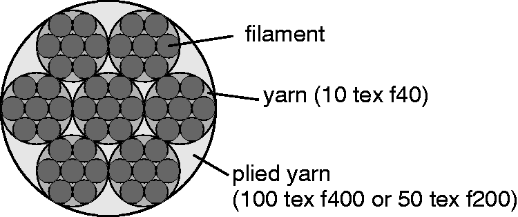

Here, Ra40, is the equivalent radius of the unplied yarn determined from the best known packaging of 40 equal circles (equals the single filaments) in a larger circle as

See Figure 3 for a schematic representation of the mathematical problem. The constants v5, v10 and v40 in equations (2)–(4) were read from tabled values as 0.370192, 0.262259 and 0.1403736, respectively [28]. The radius of the filament, rfilament, is given by circle analytics as

The cross section of the filament, Afilament, is the cross section of the unplied yarn, which is determined from the relationship of the yarn density, Tt, and the material density, ρ, divided by the number of filaments, f, as

Process model
To create the initial braided geometry, the finite element preprocessor Ansys® Workbench (Ansys Inc., USA) was used and a keyword file for the explicit finite element solver LS-DYNA® (Livermore Software Technology Corporation, USA) was then exported.
The yarns were moved by guide elements on the tracks required for the manufacturing of a round braid. The sinusoidal movement of the yarns was replaced by a linear track between three positions on each impeller in the model (see Figure 4). This simplification became necessary due to restrictions of the program used.
Movement of the yarns during the braiding process: (a) actual sinusoidal process and (b) linear movement used in the process model.
In the model, the draw-off force was applied as a force acting on the upper ends of the yarn. The measured loss of power caused by the friction of the braid on the two draw-off rollers of the braider was considered accordingly. According to the manufacturer the yarns were pre-stressed at the carrier springs with 18 g, which gives a pre-stress of 0.177 N according to equation (1). In the model, it was applied analogously to the lower ends of the yarn in the opposite direction.
The element size for the actual braid was chosen to be 0.6 mm. For the remainder of the yarns and all guide elements, the element size was set to 2 mm. The latter were used for motion and load transfer and not for evaluation purposes, such that the larger element size was justified in favour of the computing time. Shell elements were used for the guide elements, digital elements were used for the yarns. For the friction between the yarns, 0.19 and 0.25 were applied as the static and dynamic coefficients of friction, respectively.
Figure 5 shows the process model of a braid with 32 yarns. The process settings and production parameters used in the simulation were analogous to the samples prepared in the experimental tests. The density of the PES yarn was 1.39 g cm−3 and the Young’s modulus was 9.6 GPa. For the simulation of the braiding process, an equivalent cross-section has been calculated (equations (2) and (3)) that does not correspond to the geometrical dimensions of the real material surface. To set the same mechanical behaviour of the real and modelled structures, the Young’s modulus and the density were adjusted as well. As an acting longitudinal tensile force, FL, in the simulated braid should cause the same strain, Braiding process model with 32 yarns.

The equivalent Young’s modulus,

To calculate an equivalent density of the material for the simulation, the proportions of material, αmat, and air, αair, at the yarn cross section used in the simulation were determined. Those arise from:


The braid was pulled off via two rollers, which were not taken into account in the simulation model. However, the measured reduction of the draw-off force due to the friction was considered in the model. The draw-off forces in the simulation were, thus, by a factor of 1.9 lower than the forces caused by the actual weights.
Finite element structural model
To generate representative sections of the simulated braid structures, in the process simulation, the movement of the yarn guide element was stopped as soon as each yarn reached its initial position for the second time. The braided structure was exported from the process simulation. This approach is termed the ‘pre-stressed’ model, since structures are under tension. In another approach, the draw-off force was gradually reduced until it was zero. As a result, the braid sank down due to the forces that simulated the yarn pre-tension of the carrier springs. At the time at which the braiding began to subside, the braided structure was no longer pre-stressed. In the post processor, the time was analysed at which the forces were smallest in the yarn. At this time step, a portion was exported from the undisturbed area of the braided structure, which was then used as input for the structural simulations. This approach is termed the ‘relaxed’ model.
Virtual tensile tests were carried out similarly to the experiments. The length of the test specimen was chosen such that the yarn performed one whole circulation. A non-linear material behaviour was chosen for the yarns according to results of actual tests of the PES yarns. The force-strain behaviour that was implemented as the material model in table form is shown in Figure 6. Structure simulations of the braids were performed until 30% strain.
Force-strain behaviour implemented as the material model for the yarns, determined from tensile tests of 100 tex PES yarns.
Results and discussion
Geometry of braided scaffolds
Experimental tests
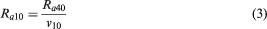
The braided scaffolds are exemplarily shown for the braiding trials with 100 tex yarns in Figure 7. Braids were fabricated at a constant impeller rotational speed. Thus, with increasing weight, the draw-off force according to equation (1) was higher and the braid was pulled off faster. This lead to less dense structures at higher draw-off weights. Braids tended to increase their diameter at higher draw-off forces.
Braided structures with (a) 16 and (b) 32 yarns, yarn fineness 100 tex, comparison of different draw-off weights.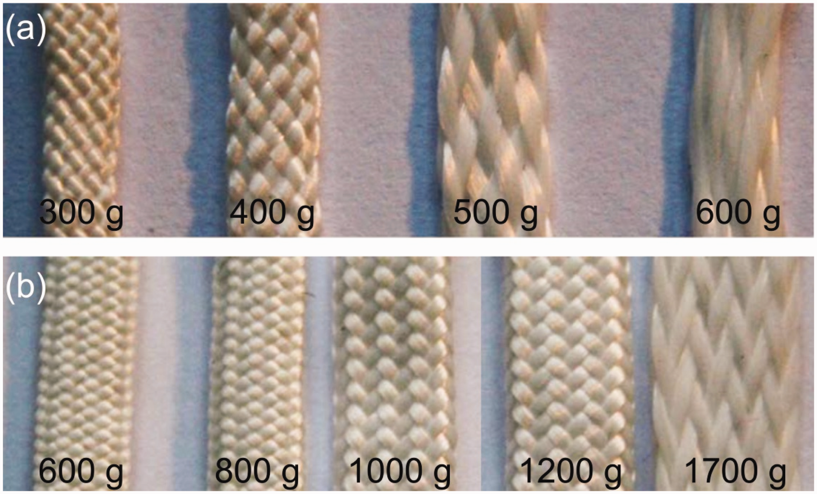
Considering the braiding angle in dependence of the draw-off weight and the number of yarns (see Figure 8), a nonlinear relationship could be observed. A higher draw-off weight resulted in a smaller braiding angle. In the case of a doubling of the weight due to a doubling of the number of yarns, braiding angles were not the same. This was attributed to the increasing friction between the yarns with increasing number of yarns.
Braiding angle, θ, in dependence of draw-off weight and number of braided yarns (16 and 32) and yarn fineness (50 tex and 100 tex); error bars showing standard deviation.
Simulation model
Braiding angles, θ, as mean (standard deviation), comparison between experimental and simulation results.

Virtual braided structures as output from the process simulation are displayed in Figure 9. The more elongated shape and the lower braiding angle with increasing draw-off force are clearly visible.
Braid geometry as output from the process simulation (16 yarns, 100 tex), comparison of different draw-of forces.
Mechanical behaviour of braided scaffolds
Experimental tests
The stiffness of the braids depends on the braiding angle. A lower braiding angle results in stretched yarns and, thus, in a higher stiffness in the longitudinal direction. Therefore, braids that were manufactured with a higher draw-off force have better mechanical properties in tension in the longitudinal axis, which is the key value for ligament replacements. This behaviour can be seen in the load–strain curves in Figure 10.
Load–strain behaviour (F(ɛ)± SD, mean ± standard deviation) of braided scaffolds with 16 and 32 PES yarns, comparison of different draw-off weights: (a) 300 g and 600 g, (b) 400 g and 800 g, (c) 500 g and 1000 g, (d) 600 g and 1200 g (respectively, 16 yarns, 100 tex and 32 yarns, 50 tex).
Because of structural elongation, the load–strain curves are initially flat, followed by a linear behaviour and a non-linear increase of the load to a maximum. Afterwards, a softening behaviour was observed for the 16 yarn braids except for 300 g draw-off weight (50 tex and 100 tex). Note that the small jump in the curves of the 32 yarn braids at approximately 400 N is due to slippage at the clamps. The load–strain behaviour was, therefore, incorrectly recorded.
It can be seen that the initial flat zone of the curve, in which a small tensile force causes a large deformation, decreases with increasing draw-off force. The structural elongation is therefore dependent on the braiding angle.
The maximum tensile force, Fmax, increases with decreasing braiding angle, as shown in Figure 11(a). This is obvious, since the tendency of the yarns to align in the direction of the tensile force, leads to a movement of the yarns until they support each other. At a small angle to the longitudinal axis, this freedom to move is considerably smaller than at a large angle. Thus, the resulting damage from the friction between the yarns is lower. Increased friction between the neighbouring yarns causes shear forces that damage individual filaments.
Mechanical parameters (a) maximum tensile load (Fmax) and (b) maximum strain (ɛmax) of braided scaffolds as a function of number of yarns, yarn fineness and draw-off weight, error bars show standard deviation.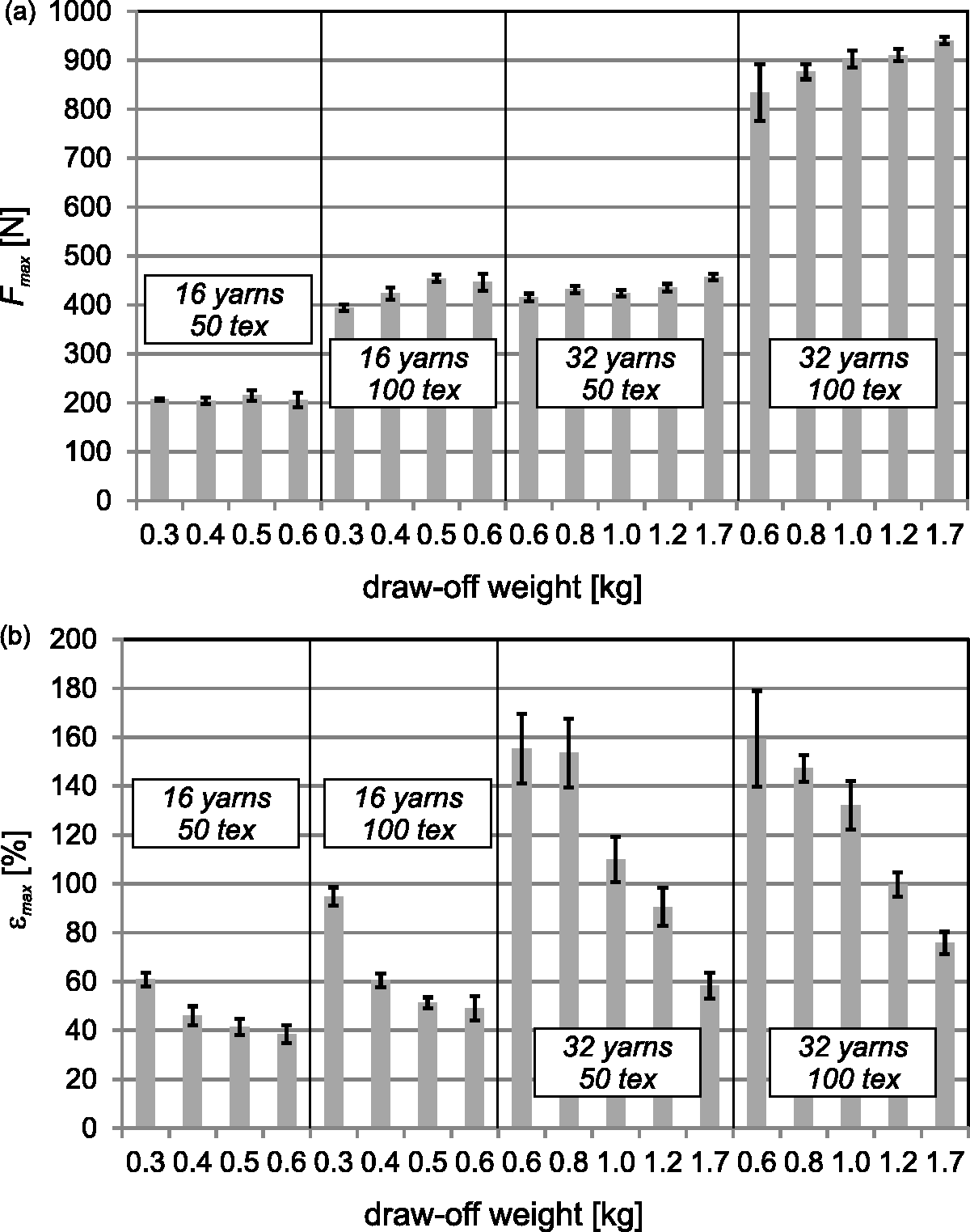
The maximum strain, ɛmax, which is the strain corresponding to the maximum tensile load, Fmax, significantly decreases with decreasing braiding angle (Figure 11(b)). This is due to significant lower structural strain with elongated fibres.
Simulation model
Significant influences of the braiding angle, the number of yarns and the yarn fineness of the applied PES yarns on the force-strain behaviour were found. Examples of structural simulation results are shown in Figure 12 for different braids. The simulation results agree in parts very well with the experimental tests. However, load–strain curves were overestimated by the modelling approach with pre-stressed structures. This model does not reproduce the structural elongation at low strains. The initial behaviour is linear instead of quadratic. The relaxed structures instead showed initial structural elongation. Thus, curves fit excellent with experiments. However, a strong increase in stiffness was noticed above approximately 15% strain. Interpenetrating yarns were partially noticed at contact areas. Those are one source of error. For a general validation of the mechanical model further analyses are required.
Examples of actual and virtual tensile tests: (a) braids with16 yarns, 100 tex, and 300 g draw-off weight, (b) 32 yarns, 50 tex, 800 g, comparison of pre-stressed and relaxed models.
Conclusions
Mechanical properties of PES braids as a demonstration for artificial ligament replacements were investigated. Therefore, braiding process parameters were varied to determine the possible range for influencing the mechanical properties. Additionally, a process simulation model was established and validated to adjust mechanical properties of future grafts based on process and material parameters without extensive experimental trials. Agreement of the achieved braiding angles between real and virtual structures was excellent for the 16 yarn braids, whereas deviations were noticed for the 32 yarn braids. In a second simulation step, a structural model was established. To represent the complex non-linear behaviour of braided structures correctly, some adaptions in the model are required in the future. With process and structural modelling approaches, the virtual mechanical testing becomes possible. Significant influences of the braiding angle, the number of braided yarns and the yarn fineness of the applied PES yarns on tensile properties were found for both the experimental tests and the simulation model. With the process model and the structural model, the basis for the application to actual ligament replacements made of resorbable polymers, such as polyactid acid (PLA) or chitosan, is developed. To reduce computation time for complex implant geometries, multi-scale models with homogenization techniques are required in the future. Also, comparison with the biomechanics of actual human ligaments will provide necessary input for the design of tailored scaffolds made with textile technologies.
Footnotes
Acknowledgement
The authors would like to thank Katarina Gille for her investigations in the scope of her thesis.
Declaration of Conflicting Interests
The author(s) declared no potential conflicts of interest with respect to the research, authorship, and/or publication of this article.
Funding
The author(s) received no financial support for the research, authorship, and/or publication of this article.