
Abstract
Esophageal stents are used as a clinical method for the treatment of a wide variety of esophageal diseases. Knitted mesh stents have such advantages as high flexibility and ease of production. In this study, an analytical approach was applied to simulate the weft knitted esophageal stents and to investigate the mechanical behavior of these tubular structures against the axial and circumferential stresses by using finite element (FE) and mathematical models. Then, the mechanical properties of the knitted structures were evaluated while the simulated food bolus was passed through the stent channel. The results demonstrated that the FE model had a good performance in simulating the mechanical properties of the esophageal knitted stents. The error of the prediction performance of the FE models was between (10–16)% and (7–11)% for the longitudinal and circumferential directions, respectively. Simulation of the food bolus passage also demonstrated that the esophageal PGA stent wall could tolerate a 7.96 kPa force and a strain of 65% by food bolus; so, it could mimic the real state of esophagus during its application. This model could be applied to design and investigate the mechanical behavior of the knitted stents in clinical application conditions.
Introduction
Esophagus is a muscular tubular organ connecting the throat to stomach. There are some diseases and disorders that can affect the performance of esophagus; these include gastroesophageal reflux disease (GRED), swallowing disorders, Barrett’s esophagus, etc. Different solutions have been developed to treat esophageal disorders, such as endoscopic and surgical treatments, radiofrequency ablation, esophageal stents, etc.
Esophageal stents have been proved as an effective clinical treatment, improving the life quality of the patients and their nutrition condition [1]. Several types of esophageal stents are currently available; they are made from metal alloys and durable polymers. These stents are used to treat different benign and malignant esophageal disorders. Currently, self-expanding plastic stents (SEPS) and self-expanding metal stents (SEMS) are considered as safe and low-cost solutions for the treatment of the esophagus diseases [2].
Today, the esophageal stents are commercially manufactured by different trade names, such as Polyflex®, Alimaxx-ES EndoMAXX®, Evolution®, etc. [3]. There have also been several attempts to design and characterize the self-expanding plastic and metal stents with additional features including biodegradable [4–9], biocompatible [10,11], fully covered [12–15], partially covered [16] and uncovered stents. However, SEMS and SEPS may cause different complications during their placement within esophagus. The major complications with esophageal stents are tumor ingrowth, migration, chest pain, fistulas and bleeding [17].
Textile-based esophageal stents have also been investigated in order to tackle some current complications of metallic and polymeric stents, such as tumor ingrowth and the formation of the new structures caused by the migration of SEMS and SEPS. Knitted stents are commonly used as flexible candidates for the treatment of the esophagus disorders. Knitted structures are widely used in medical applications and tissue engineering due to their good mechanical properties and extensibility against the applied forces [18]. There are also some commercially available knitted stents including EGIS®, Ultraflex®, and Wallflex®. In addition, there are several studies on the newly knitted stents designed esophageal treatment [9,19–22]. While all previous studies have focused on experimental in-vitro characterization of the esophageal stents, less attention has been paid to modelling the behavior of these structures in practical applications. However, Garbey et al. have studied the migration behavior of the esophageal stents by simplified mathematical models [23]. They modeled the esophagus wall as a Kelvin-Voigt viscoelastic material and assumed a linear stress-strain relationship for the esophagus muscles. Their results showed that the developed model had high accuracy in comparison with the clinical results in predicting the migration behavior of the stents. However, they only investigated the migration properties of the stents and did not consider the longitudinal and circumferential deformations of the stents in their models.
In this work, we also conducted a literature review on recent attempts on modelling the mechanical properties of the weft knitted structures, especially for tubular knitted fabrics. For example, van der Merwe et al. evaluated the mechanical properties (mainly focusing on radial compliance) of the commercially available Nitinol® wire knitted meshes by computational FE models [24]. They used an expander model to create a symmetric radial displacement to evaluate the radial compliance of different Nitinol structures (differing in loop style). The results of this study were, however, limited to symmetrical static deformations and the dynamic deformation of the stent wall in circumferential direction was not considered. Kurbak and Ekmen have also proposed a geometrical approach for modeling the small diameter knitted technical fabrics [25]. Nevertheless, they only investigated the widthwise curling behavior of the plain knitted fabrics based on the suggested geometrical model. Further, Ochola et al. have studied the repairing process of the tendon tissues by braided tubular fabrics via modeling the tubular structure [26]. However, there is only a uniaxial loading model considering the real function of the tendon.
Viscoelastic models have also been used to investigate the mechanical properties of the weft knitted fabrics. Htoo et al. have, for example, modeled the weft knitted fabrics in a three-dimensional manner by using a suggested mass-spring system for yarns [27]. Their model did not give a precise result for tensile properties, as compared with experimental test, due to ignoring the friction between loops. Yekrang et al. have also modeled the knitted tubular structures by viscoelastic elements [28]. They considered several rheological combinations to investigate the mechanical behavior of the weft knitted tubular structures in the axial and circumferential directions. However, they did not investigate the circumferential deformation of the tubular knitted fabrics while they were passed through a solid material. Some researchers have also worked on the numerical modeling of the biaxial weft knitted structures for composite applications [29,30]. In these studies, the biaxial weft knitted fabrics were modeled numerically by macro and meso-scale FE methods. The results were compared with the experimental data. These studies include some investigations on the modeling of the shape formation of the weft knitted fabrics and their mechanical properties under biaxial loading; however, they did not consider the fabric deformations in a tubular shape.
The literature review, therefore, shows that although there are some attempts on modeling the mechanical properties of the weft knitted structures, there is a lack of enough studies concerning the mechanical behavior of the weft knitted structures in the uniaxial and circumferential directions based on a tubular shape that could be critical in vascular and esophageal applications. In addition, there is no study on modeling the behavior of the tubular stents against dynamic circumferential loading, especially when the food is passed through the stents channel. In this study, we, therefore, tried to model the tubular knitted esophageal stents using the finite element (FE) method and to investigate the expansion behavior of the stents during the passage of food bolus in the real state of application. Accordingly, tubular weft knitted structures with different yarn properties were modeled using numerical and mathematical models; the results were then compared with the experimental data. It was shown that there was a reasonable agreement with the experimental data based on the FE modeling; the developed stents could be used to mimic the required expansion exerted circumferentially by the food bolus on the PGA stent wall. The developed model could be, therefore, applied to design the esophageal stents and investigate the stent expansion behavior in real situations.
Materials and methods
Materials
Stents had been knitted by polyglycolic acid (PGA 60 tex- Supabon Co., Iran) and polyamide Nylon 6 FDY yarns (PA6 62 tex- Saba Tire Co., Iran).
Knitting of the stents
Knitting process was performed by the double jersey V-bed weft knitting machine (Santagostino, 12 gauges). All stents were knitted in the plain structure. The PA6 stents were knitted with different stitch densities (Figure 1) to evaluate the model performance. Table 1 shows the properties of the knitted fabrics; these included the courses per centimeter (CPC), wales per centimeter (WPC), stitch density, width, thickness and grams per square meter (GSM) of the tubular structures. Ten samples were examined for physical properties and the average and SD values were reported.

Weft knitted tubular structures made by (a) PA6 yarn, (b) braided PGA yarn, and (c) SEM image of the weft knitted structure made by the braided PGA yarn.
Structural features of the weft knitted tubular stents.

Conditioning of the knitted stents
The knitted stents were washed prior to mechanical tests to wash out the chemical agents and contaminants made during the knitting process. The knitted fabrics were washed by ethanol 70% (v/v) for 30 min at 35 °C using the Innova-4080 incubator (Eppendorf Co., Germany). Then, the samples were rinsed using distilled water and the residual ethanol was removed. Finally, the knitted samples were dried at room temperature for 24 hr.
Mechanical characterization of the yarns and tubular structures
Zwick universal machine 1446-60 (USA) was applied for mechanical testing procedure. Mechanical properties and elastic modulus of the PA6 and PGA yarns were measured according to ASTM D2256: 2015 standard method, by using the single-strand technique. Ten samples were tested and the results were averaged. Table 2 shows the mechanical properties of the PA6 and PGA yarns.
Mechanical properties of the yarns.

All tests were performed before the jamming point of the knitted structures. Jamming occurs when the loops in the weft knitted fabric reach their maximum tensile strength. After that, the applied force could be sustained by yarns and the contribution of the knitted structure in mechanical behavior might be negligible [31].
Longitudinal tests were performed at the strain rate of 10 mm/min and the test lengths were set at 30, 60 mm for the axial and circumferential directions, respectively. Five tests were performed for each samples in both directions and the results were averaged. Two designed fixtures were used to measure the mechanical properties of the samples in the circumferential direction. Fixtures were made with the flat and smooth surfaces to prevent any friction during tests.
The friction coefficient of the PGA and nylon yarns was measured according to the generalized hanging fiber method [32]. As illustrated in Figure 2(c), the test specimen was hanged from the upper load cell of the tensile meter using a certain mass (M) and the same yarn was placed horizontally in contact with the hanged yarn. Then, the U-shaped plate gripped within lower fixture was moved downward. The mass weight was selected as 65 g according to the ASTM-D3412 instruction. The length of the test specimen and the horizontal yarn was 20 cm and 5 cm, respectively. L1, L2 and φ values were also set as 6 cm, 15 cm and 21.8°, respectively. Test speed was adjusted at 5 mm/min. Ten tests were performed for each yarn and the results were averaged for the obtained friction forces. The friction coefficient of the yarns was calculated as follows: Mechanical testing of the tubular stents in (a) axial and (b) circumferential directions (designed fixtures for the circumferential test), and (c) hanging the fiber method for measuring the friction coefficient of the yarns.

Analytical simulation of the tubular knitted stents
Nonlinear tensile behavior of the knitted fabrics could be expressed by an exponential equation, as follows [33]:

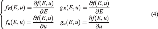

This analytical model was used to calculate the theoretical values of the mechanical properties in both directions. Matlab R2012a software was also applied to solve these equations using the Newton-Raphson numerical method. The average values of the initial tensile modulus, force and elongation before the jamming point were used as the initial values to calculate the tensile parameters by the recurrence relations. The termination condition was set as error of 2 cN/tex and 0.01 for E and u values relative to experimental results, respectively.
Modeling the unit stitch and the whole structure of the tubular knitted stents
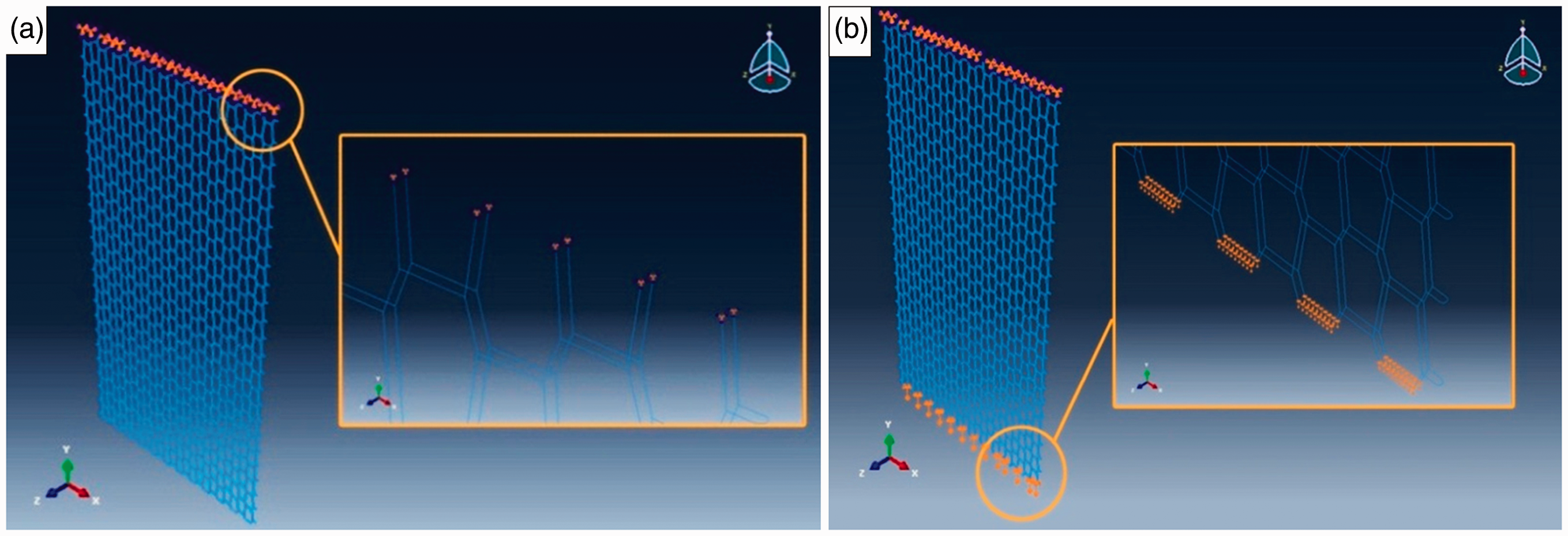
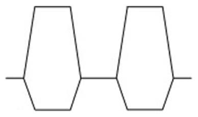
The hexagonal model of the weft knitted fabric, as suggested by Wu et al. [34], was applied to model the structural unit of the tubular knitted stents. Abaqus 6.10 software was used to model the fabrics. The unit cell was developed with the deformable planar wire sketch feature of the software. According to the proposed model, the coordinates of the points A, B, C and D in Figure 3(a) were calculated using the structural parameters of the knitted fabrics; these included the courses per meter (CPC) and wales per meter (WPC), as follows:

(a) The unit cells of different knitted stents developed by Abaques software, and (b). rhe whole structure of the tubular fabric modeled by the montage module.
After modeling the unit stitch, the unit cells were merged together to develop one side of the tubular fabrics. Fabrics length was considered as 3 cm (the same as the gauge length in the axial tests) and the number of loops in the knitted fabric was determined according to the structural properties (WPC and CPC) and the width of the knitted structures. The dimensions of the last loops in the axial direction of the modeled fabric were incomplete due to different values of WPC and CPC for the PGA and PA6 fabrics (Figure 3(b)).
The montage module was used to develop the tubular structure. For this purpose, two layouts of one side of the fabrics were linked together using semicircle sections. This work was done by cutting 1/5 of the loop foots in both sides of each course and substituting it with a semicircle of diameter equal to the cut length.
Knitted fabrics show the anisotropic behavior under loading condition. Furthermore, these fabrics may suffer a large deformation under small stresses. Therefore, the knitted fabrics could be modeled with hyperelastic structures [35]. Hyperelastic models are used for materials with the non-linear stress-strain behavior. This model has also been applied to model the stress-strain behavior of the non-linear incompressible elastic tubular fabrics [36].
Fabric characteristics including the yarn diameter, the direction of the loop deformation under loading, and material type were provided for the model. A hyperelastic material was used to model the structure of the tubular knitted fabrics. Nominal force and elongation values were also introduced to the software. A hyperelastic model should satisfy a strain energy function. Strain energy potential determines the solving method of the non-linear equations to simulate the material based on the experimental data of the uniaxial, biaxial, pure shear and simple shear tests. In this research, the obtained data of the uniaxial tests were used to evaluate the strain energy potential. Four strain energy potentials including the Ogden (N = 1), Neo Hookean (N = 1), Yeoh (N = 3) and reduced polynomial (N = 4, 5) were applied. These strain energy potentials were trained to investigate the material stability under different strains and uniaxial, compressive, biaxial, planar and volumetric modes. Strain energy potential and experimental curves were visually compared and the strain energy potential with the best fitting performance was selected for the model.
PGA and nylon yarns were designed as a beam element with the circular profile. Two profiles with the circular cross sections of 0.152 and 0.147 mm of radius were created for nylon and PGA yarns, respectively. Beam element section orientation was also set at the y (0,1,0) axis.
Simulation of the axial test
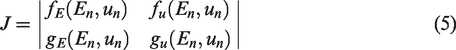
The uniaxial longitudinal test was simulated using the step module in two steps, including the definition of the boundary conditions and the application of the tensile force to the stents based on the static general analysis method. Time period and increment size were set large enough to prevent divergence. The quasi-Newton approach was also selected as the solution technique to solve the non-linear equations. Boundary conditions were specified in a way similar to that done for the experimental tests. In this case, the upper part of the tubular fabrics should be fixed in the upper fixture and the lower part of the fabrics could move downward under a constant rate of elongation (CRE). Both translational and rotational degrees of the freedom of the top part were constrained to remain fixed (around the x, y, and z axes). Figure 4(a) shows the specification of the boundary conditions in the upper section of the modeled tubular knitted fabrics.
Simulating the performance of (a) fixed and (b) movable fixtures in the CRE axial tests of the tubular knitted fabrics.
The bottom part of the stent was elongated to the average elongation of the experimental tests, so it was equal to 13.67, 15.16, 17.11, and 12.13 mm for PA6-1, PA6-2, PA6-3 and PGA stents, respectively. Tensile force was applied in the y-axis and other degrees of the freedoms were constrained to simulate the fixed position of the bottom part of the stent. Figure 4(b) demonstrates the performance of the bottom movable fixture applying the constant rate of elongation to the lower part of the tubular fabrics.
Seeding and meshing procedure were also performed using the mesh module of the software. B31 element type (3 D beam, 1st-order interpolation Linear Bulk viscosity) was selected for fabrics.
Simulation of the circumferential test
Tubular stents were created by structural units in the same way done for the axial test. The length of the stents was also set at 60 mm, the same as the experimental condition. However, the connection type of the front and back side of the tubular fabrics was designed in a way different from that for the structures used in the axial direction. According to thickness of the circumferential fixtures (1.7 mm), it was assumed that there was at least a complete knit stitch in contact with the fixture thickness. The maximum length of the fabrics in contact with fixtures was also assumed to be 2 mm. According to this assumption and different loop lengths of different fabrics, there were different loop structures in contact with fixtures in the thickness direction. The loop structures in contact with these fixtures are shown in Table 3.
Different loop structures in contact area across the thickness of the fixtures designed for the circumferential test.


The fixtures of the circumferential test were designed by the sweep method with dimensions being the same as those in the experimental condition. The discrete rigid material was used to create the fixtures. Figure 5(a) and (b) show the dimensions of these fixtures.

Dimensions of the created fixture for the circumferential test in: (a) side and (b) cross section views, and (c) simulation of the tensile test in the circumferential direction by the created fixtures.
For the circumferential test simulation, the designed knitted tubular fabrics were placed within created fixtures using the montage module of the Abaqus software. Figure 5(c) demonstrates the simulation process of the lateral tensile tests for the tubular knitted fabrics. The upper fixture was fixed and the lower fixture was moved downward under C.R.E condition.
Some fabrics features including the material type, yarn radius, beam element type, etc. were assigned to models in the same way done for the axial test. However, the experimental results in the circumferential direction were introduced to the hyperelastic model; these included the nominal circumferential force and elongation values. The quasi-Newton method and static general analysis technique were also used to develop the final model. In this case, the contact type between the fabric and fixture was defined using the interaction module of the software. Otherwise, the fabric gripped between fixtures would not be considered as a single object. It was assumed that the contact between the fabric and fixtures was without friction. Figure 6(a) shows the contact area between the upper fixture and tubular fabric. As can be seen, three surfaces including the fabric and external surfaces of the upper and lower fixtures should be defined for the model. The surface-to-surface contact type was defined in the initial step, node-to-surface was selected as the discretization method, and small-sliding was assigned as the contact formulation to the model.

(a) Definition of the contact areas between the tubular fabric and the top fixture in the circumferential test, and (b) boundary conditions in the top and bottom fixtures.
Definition of the boundary conditions in the circumferential direction was done in a way different from that of the axial test. In this case, the top and bottom fixtures were exposed under loading conditions. During this test, the knitted fabric would be displaced from fixtures and stitches shrinkage could occur due to its structure and elasticity features. In this study, we assumed that this shrinkage occurred in the left side of the fabrics and other stitches in the tubular structure had their real deformation according to the applied force. For this purpose, the left side of the fabric was constrained for deformations under loading conditions.
B31H element type (3 D beam, the 1st-order interpolation Linear Bulk viscosity with hybrid formulation) was assigned to the developed structure in the mesh module of the software. The hybrid elements were used to deal with the incompressible or inextensible behavior of the materials. In these cases, it was numerically difficult to compute the axial and shear forces in the beam using the displacement-based finite element methods. Hybrid formulation is typically used for very rigid beams in axial and transverse shear deformation, such as flexing long pipes or cables. This formulation makes these elements more expensive and efficient, as they could generally converge more quickly in large deformations.
Simulation of the food bolus
A discrete rigid sphere with the diameter of 10 mm was simulated by the revolution technique as food bolus; it was inserted to the tubular knitted esophageal stent (Figure 7(a)). A normal food bolus of 10 mm diameter would exert a pressure of 3–5 kPa to the esophagus wall [37].

(a) Simulated sphere with 10 mm diameter as the food bolus, (b) the ideal structure of the tubular knitted fabric, (c) transition of the food bolus through the tubular stent with 3 cm length, and (d) insertion of the simulated bolus into the fabric channel with 1 cm length.
The assigned features for the circumferential tensile test model were applied for the tubular structure of the PGA fabric to simulate the food bolus transition from the esophageal stent. Knit loops were assembled together into an ideal form of the fabric structure. In the ideal structure, unit stitches with equal dimensions form the tubular shape of the PGA fabric. The ideal structure was formed by 24 stitches in a circular shape for each course, and stitches occupied 15° of the cross section profile of the tubular structure (Figure 7(b)).
Two cases were considered for the simulation of the food transition from the tubular fabric. In the first one, food bolus was completely placed into the tubular scaffold and then moved 1 cm downward. The length of the fabric was set at 3 cm and the food bolus was moved to the middle part of the fabric channel (Figure 7(c)). This was modeled to investigate the structural behavior of the knitted esophageal scaffold during the transition of the food. In the second model, the simulated food bolus was placed out of the fabric channel with the length of 1 cm. Then, this sphere was inserted into the tubular structure and moved downward to the bottom of the knitted fabric (Figure 7(d)). In this case, the force of a bolus of 10 mm diameter that acted on the inner wall of the PGA tubular knitted fabric was measured. In both cases, the fabric deformation in the y- direction was limited and the fabric was allowed to deform in the x- and z-axes.
The flowchart of Figure 8 summarizes the process of the mathematical and numerical modeling (by the FE method) in this work.

The schematic flowchart showing the methodology of the analytical and FE modeling of the tubular knitted stents.
Results and discussion
Mechanical properties of the stents
Mechanical and frictional properties of the knitted stents have been listed in Table 4. The friction coefficient of the PGA and PA6 yarns was also calculated to be 0.22 ± 0.02 and 0.20 ± 0.01, respectively.
Mechanical properties of the tubular knitted stents.

The results showed that the increase in stitch density led to enhancing the maximum force before jamming point in the axial direction for the nylon fabrics. In addition, the maximum values of the axial elongation were also raised with the increase in the stitch density. In contrast, the circumferential results showed that there was an optimum value for stitch density. Increasing the stitch density (up to 24%) caused the enhancement of the maximum force before jamming point. However, a significant increase in stitch density (up to 92%) led to a dramatic force drop. Thus, the stitch density should be controlled to reach the appropriate elastic properties of the tubular knitted fabrics.
Results of simulations in the axial direction
Figure 9(a) to (d) show the comparison between simulation, analytical and experimental results for the axial loading of the knitted stents. All results were obtained up to elongation at the jamming point of the fabrics. The results showed that the FE model and analytical method had a good performance in the low strain values. Simulation results also diverged with the increase in strain. This trend could be attributed to the decrease in the dependence of the simulation on the experimental data at the higher strains and the increase of the applied forces in both axial and circumferential directions to the cantilever beam. This significant increase of force in the simulated models could also be due to the absence of yarn slippage and the incompressibility of the hyperelastic material.

The comparison between experimental, theoretical, and simulated FE model results of the axial tensile tests of the knitted stents for (a) PA6-1, (b) PA6-2, (c), PA6-3 and (d) PGA knitted stents.
Except for the PA6-3 sample, the force-elongation curve of the experimental data intersected the curve of the analytical models with the increase in elongation. This could be due to the increase in the contact area of the knitted loops during the uniaxial testing, which could not be evaluated in the analytical method. However, this trend could also be expected for the PA6-3 sample at the higher strains.
PGA and PA6-1 samples were modeled by a similar loop length (close stitch densities) and loop shapes (referring to Table 3). The force-elongation curves in Figure 10(a) and (d) show that the PGA and PA6-1 fabrics had a similar force-elongation trend and the obtained values for the maximum force and elongation were also close to each other.

The comparison between experimental, theoretical, and simulated FE model results of the circumferential tensile tests of the knitted stents for (a) PA6-1, (b) PA6-2, (c) PA6-3, and (d) PGA knitted stents.
Results of the circumferential loading simulation
Figure 10(a) to (d) show the results of the experimental, theoretical and simulated FE model for the circumferential uniaxial tensile tests. All results were evaluated up to elongation at the jamming point of the fabrics. The results indicated that the analytical and FE models had a good performance in low strain values for the axial direction. However, it was obvious that the FE model had a better performance with the higher strain values in circumferential tests.
Comparison of Figures 9 and 10 shows that the analytical model had an obviously better performance in the axial direction, as compared to the circumferential tests, in terms of predicting the experimental force-elongation curve. The axial tests were modeled in the condition that the 30 mm width of the fabrics was in contact with the jaw; in contrast, in the circumferential direction, the full length of the fabrics (60 mm) was held by the test jaws. As a result, the more stitches were involved in the circumferential tests. Thus, more calculations would be performed and the divergence in results could be higher than that in the axial direction.
The results showed that the FE model had a better performance in the higher strains in comparison to the axial tests. Except for the PA6-3 sample, the experimental curves also intersected the analytical force-elongation results due to the increase in the contact area of the yarns during the tensile test. The better performance of the FE model in the circumferential direction could be attributed to the lower number of elements rather than the axial direction. In fact, by reducing the number of elements and decreasing the stitch density of the knitted stents, the experimental results and FE model would be in a good agreement. The results also showed that the FE models could act appropriately in the lower strain values.
Figure 10(c) represents the force-elongation curves of the PA6-3 sample. As can be seen, increasing the stitch density (up to 90% more than that of the PA6-1 sample) made a rigid structure in the circumferential direction and the knitted stent showed a less elastic behavior and elongation in comparison to other samples. It was obvious that the FE model could predict the approximately linear behavior of the PA6-3 sample in the circumferential direction. However, the analytical model kept the nonlinear behavior of the knitted structure. The analytical model was based on theoretical relationships and modeling was performed by limited structural parameters of the fabrics. So, the nonlinear nature of the equations preserved the nonlinearity of the curves.
According to Figure 10(a) and (d), the PGA sample reached its jamming point more quickly than the PA6-1 fabric (27 N versus 61 N for PGA and PA6-1 stents, respectively). Figure 9(a) shows that the PA6-1 sample started elongation with a slight slope up to 80% of its ultimate strain and then reached to the jamming point with a significant increase in its stress. Although the PGA and PA6-1 samples had similar properties including yarn count, stitch density and loop shape (as shown in Table 3), the PGA sample, due to its braided structure, exhibited more frictional property in contact with other loops, thus reaching to its jamming condition more quickly.
The prediction performance of the FE models was also evaluated by the quantitative statistic so-called root mean squared prediction error (RMSPE). The RMSPE parameter is defined as the standard deviation of the differences between modelled and observed values. RPMSE, which is usually used as a measure of the model accuracy, is mathematically defines as follows:

In order to find the force values predicted by the FE model at different elongations, the polynomial regression method was used to fit the force-elongation curves predicted by the model. The force-elongation curves were fitted in the axial and circumferential directions by 4th and 5th polynomials, respectively. The general form of the polynomials was y = ax5 + bx4 + cx3 + dx2 + ex + f.
Fitting process was performed by the Matlab R2012a software. The regression coefficients are listed in Table 5. The R-squared (R2) value of the fitted polynomials (greater than 0.99) showed an excellent fitting performance for the force-elongation curves estimated by the FE models.
The regression coefficients for the fitted curves on the force-elongation curves developed by the FE model.

Force values estimated by the FE model were calculated by fitted equations at defined elongations and compared with the observed force values. The observed and calculated force values were plotted for different structures at the axial and circumferential directions. In order to evaluate the model performance, the experimental and respective modeled values were fitted by the linear regression method and plotted against the y = x line (red color). Figures 11 and 12 show the experimental and modeled force values for different structures at the axial and circumferential directions, respectively.

The comparison between experimental and calculated force values obtained from the FE model of the axial tensile tests of the knitted stents for (a) PA6-1, (b) PA6-2, (c) PA6-3, and (d) PGA knitted stents.

The comparison between experimental and calculated force values obtained from the FE model of circumferential tensile tests of the knitted stents for (a) PA6-1, (b) PA6-2, (c) PA6-3, and (d) PGA knitted stents.
The rnRMPSE(%) value as a metric of the accuracy of the FE models was calculated for the axial and circumferential directions of different structures and materials. The calculated data are listed in Table 6.
rnRMSPE(%) values of the FE models for the axial and circumferential mechanical tests.

Results, as shown in Figure 11 and Table 6, revealed a good performance for the FE model in predicting the mechanical behavior of different tubular structures in the axial direction. The prediction error of the FE models based on the calculated rnRMSPE(%) values was in the range of 10-16% and 7-11% for the axial and circumferential directions, respectively. The results also showed that the FE model had an acceptable performance in both directions in predicting the mechanical behavior of the knitted stents.
Simulation results for the passage of the food bolus
Two cases were considered for the simulation of the food transition from the PGA tubular stents. In first case, the food bolus was completely placed into the tubular stent and then moved 1 cm downward. In this case, the expansion behavior of the esophageal stent was evaluated for the real state of the application. In the second state, the simulated food bolus was inserted into the tubular knitted stent out of the structure and then moved 1 cm downward. Figure 13 represents the results of the FE model for these cases.

The test results obtained for the simulation of the food bolus passage within the modeled knitted PGA stent (a) case 1: real state of the application, and (b) case 2: the food insertion out of the stent.
The esophagus wall would experience a 50% increase in diameter by the normal pressures of (3-5) kPa from a food bolus with 10 mm diameter [30]. The results obtained by the FE model showed that a food bolus of 10 mm diameter could exert a normal pressure of 7.96 kPa on the PGA knitted stent, thereby imposing a 65% increase in diameter in the stents. These differences in force and strain values could be attributed to the rigid state of the simulated food bolus in the FE models. The food bolus in the real state has a soft and flexible texture when passing through the esophagus channel; therefore, it could exert a lower stress on the esophagus wall. In addition, restricting the degree of freedom in the FE models could be a source of error. The esophagus wall has a flexible and soft tissue without any constraints in all directions. Generally, the results of the FE models showed that the PGA stent could mimic the esophagus expansion behavior during the application state.
Conclusion
Textile-based esophageal stents could be used to overcome the complications of the metallic and polymeric stents. Knitted mesh stents have such advantages as high flexibility and ease of production. In this study, different structures of the weft knitted esophageal stents were simulated by FE and mathematical models and the mechanical behavior of these tubular structures was investigated in the axial and circumferential directions. The results showed that the FE models had a higher accuracy in comparison to the analytical models in simulating the mechanical properties of the knitted stents. The performance of the FE models was also evaluated by the quantitative statistic so-called range normalized root mean squared prediction error (rnRMSPE). The results indicated that the FE models could estimate the mechanical behavior of the knitted stents by 7-16% error in both directions. However, the performance of the FE model was better in the circumferential direction. The mechanical property of the PGA knitted stent was also evaluated during the passage of a simulated food bolus through the stent channel. The results showed that the PGA stents could mimic the esophagus behavior in the real states of application. The developed model, therefore, had a good performance in predicting the mechanical behavior of the esophageal knitted stents. The developed model could be applied to design and investigate the mechanical properties of the knitted stents during clinical application conditions.
Footnotes
Declaration of conflicting interests
The author(s) declared no potential conflicts of interest with respect to the research, authorship, and/or publication of this article.
Funding
The author(s) received no financial support for the research, authorship, and/or publication of this article.