
Abstract
In the smart textile area, textile antennas integrated into people’s clothing functioning as the wireless signal transmission devices have gained increasing attention in recent decades. In this study, a textile conformal dipole antenna was designed to work at the frequency of 915 MHz. The radiation elements of the antenna were adhered directly onto the stitched polyester fabric substrate to get the conformal effect. The measured results showed that the antenna had good performance with the return loss value and typical omnidirectional radiation patterns. To investigate the effect of textile substrate on the antenna performance, models for stitched and plain weave structures were built and the value of root mean square (RMS) surface error was calculated using integration methods. Then an acceptable range of operation frequencies versus RMS was marked out for estimating the reliability of textile substrate. The calculated RMS of our designed antenna was 0.25 mm, which was in the acceptable range area indicating the proper antenna design. Finally, the relationships between the critical frequencies and fabric parameters such as yarn thickness and density were studied, which gives the direct guideline for selecting the fabric as the substrate for textile antennas.
Introduction
A wearable computer is an electronic device capable of storing and processing data that is incorporated into personal accessories. As more and more people begin to utilize these devices, the evolution of wearable technology will rapidly advance. One of the typical modern examples for wearable technology is Fitbit system, which allows end users to track their personal time, distance, pace, and calories via a wristband. Distinct from wearable computing, electronic textiles, also known as smart textiles, focused on the integration of textiles with electronic elements like microcontrollers, sensors, and actuators. The application for electronic textiles includes sports training data acquisition, monitoring personnel handling hazardous materials and tracking the position and status of soldiers in action, etc. In these cases above, short-range communications will play an increasingly important part for short-range data transfer, and thus antennas, as transmitters and receivers, would be an ideal choice.
Textile antenna, the antenna integrated within the garment without interfering daily activity of end users, is flexible, lightweight, comfortable, and reliable for the electronic textiles system. In the textile antenna system, the conductive radiation elements are usually fabricated on the surface of textile substrate. Many researchers have focused on the design and fabrication of different types of textile antennas by changing the patterns of the conductive elements [1–5]. However, no report, to our knowledge, has been found on focusing the effect of textile substrate on the antenna properties. Using fabrics as the textile substrates, the existence of waviness of yarns would influence the conductive radiation surface and subsequent radiation properties, which will not occur in the case of traditional rigid composite materials plane substrate. Therefore, it is worth investigating how the surface roughness caused by the waviness would affect the antenna performance. In this study, the effect of textile substrate surface roughness on the antenna performance was discussed and the root mean square (RMS) of the surface error of the antenna was calculated based on our built model. At the same time, the relationship of fabric structure parameters including yarn thickness and density between the critical frequencies was investigated to give guidelines in selecting suitable fabric substrates for the textile antennas.
The type of antennas we chose for this study is the dipole antenna due to its simplest structure in the antenna family [6]. The antenna has two arms (radiation elements) on the substrate with the length of a half of wavelength, showing small volume and light weight advantages. Therefore, it is easy to integrate this type of antenna into textiles. In addition, a standard dipole antenna will produce an omnidirectional pattern with linear polarization, which is suitable for the communication with uniform coverage for indoor environments. As for the materials of textile substrate for the textile antennas, low dielectric value of this material is very important and beneficial to reduce surface wave losses [7, 8]. The properties of textile materials such as mechanical and water absorption properties should also be considered for the real application [9–11]. In this study, we chose polyester woven fabric as the substrate of the antenna, which is good in tensile strength, water absorption, and manufacture cost [12]. As the substrate of the antenna, the dielectric constant and loss of polyester are 2 and 0.0045, respectively, becoming an ideal textile substrate.
The paper is organized as follows: the textile dipole antenna was designed using the simulation software at the central frequency of 915 MHz and this frequency is one of the typically used frequencies for Zigbee/IEEE 892.15.4 in the short-range communication. In the fabrication process, a type of conductive fabric as the radiation elements was directly adhered onto the polyester fabric substrate to form a conformal antenna. Then, the simulated and experimental return losses and radiation patterns of the antenna were compared. Finally, the effect of surface roughness of the textile substrate on the antenna performance was discussed by building the fabric models, and the relationships of yarn thickness and density between the critical frequencies were determined.
Design and experimental
Design and fabrication
A half-wave symmetric dipole antenna was designed to work at a central frequency of 915 MHz. An antenna design tool, high frequency structural simulator (HFSS), was used for the design and simulation. The configuration of the antenna structure is shown in Figure 1, where the dark parts are the dipole arms as the conductive radiation elements and the light parts are the textile substrate. On the one side, the copper-/tin-coated nylon conductive fabric (provided by Jiaxing Microwave Shielding Material Factory, China) with the surface resistance of 0.136 Ω/sq was adopted to form the radiation elements. On the other side, 10-layer stitched pure polyester fabric with the total thickness of 2 mm was used for the textile substrate. The detailed description for the parameters of the designed antenna is listed in Table 1.
The configuration of the antenna structure. Detailed description for the parameters of the designed antenna.

For the feeding process, a coaxial cable feeds radio frequency current to the antenna as an unbalanced feeder. Since the half-wave symmetric dipole antenna is a feeding-balanced antenna, a balun (the black area in Figure 2) was usually assembled between the radiating element and coaxial connector to convert the unbalanced signal to balanced signal for better impedance matching [13].
The schematic of the dipole antenna connected with a balun.
Antenna performance test
To characterize the antenna performance of the textile antenna, the return loss and radiation pattern, as the most important parameters, were required to be measured. The return loss of an antenna could be expressed as

Results and discussion
The return loss
The simulated and experimental return losses of the textile antenna are shown in Figure 3. The return loss of the measured antenna was −15.3 dB at the central frequency of 920 MHz, while the value of the simulated antenna was −22.6 dB at the central frequency of 915 MHz. In addition, the bandwidth of the measured antenna was 7.07%, which was 1.56% lower than the simulated result. In general, the measured result agreed well with the simulated one, indicating the feasibility of this fabrication method for the textile-based antenna. However, it is noticed that there is still a small difference between the measured and simulated results, which was mainly related with the size controlling on the textile radiation elements for this type of antenna, and this type of difference or shift could be minimized by using the aid of automatic machines with high precision control system.
Measured and simulated return loss of the antenna.
The radiation pattern and gain
Figure 4 shows the measured and simulated radiation patterns of the textile antenna. It can be seen that the measured results in E and H planes, which are two reference planes of the antenna, exhibited the typical dipole antenna radiation pattern. In the E plane, the highest gain is at around 0 and 180°. In the H plane, the relatively equal value in 360° range was achieved. At the same time, the measured radiation pattern had good agreement with the simulated one for both E plane and H plane, indicating that the desired radiation directivity of the designed antenna was obtained through this study. For the measured antenna gain value, this antenna had 3.4 dBi at the central frequency showing adequate efficiency of the antenna.
Measured and simulated radiation patterns of the antenna: (a) E-plane and (b) H-plane.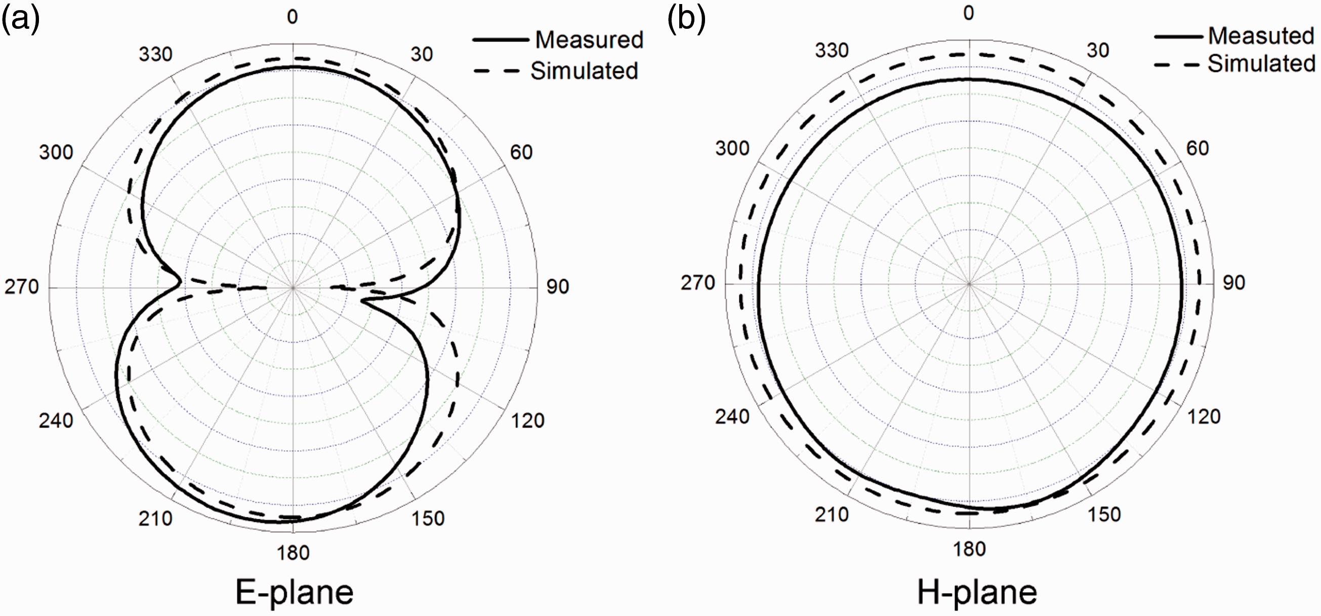
Discussion on the effect of surface roughness on the antenna performance
Different from the traditionally manufactured dipole antennas where the substrates are rigid and flat composite plates, our designed antenna was fabricated on textile fabric substrate. Assuming the radiation elements were perfectly adhered onto the textile substrate during fabrication process, the surface roughness caused by the waviness of textile substrate itself will be transferred to the radiation elements, thus leading to the undetermined antenna electromagnetic properties. Therefore, to discuss the effect of the surface roughness on the antenna performance in detail is of great importance for this type of textile antenna.
The surface roughness affects the antenna performance primarily due to the surface error, which is the height deviation of the manufactured surface from the traditional rigid surface [14, 15]. The root mean square (RMS) value of the surface error is a standard parameter used to characterize the random error of the surface. Generally, the RMS surface error of an antenna is expressed as follows [16]

For our designed antenna, since the substrate is the stitched ten layers of fabrics, the surface roughness mainly resulted from the sewing thread waviness along the thickness of the fabrics. A model could be built with the embossments of the sewing yarns taken into consideration for calculating the RMS [17]. The schematic configuration of the sectional view of the sewed substrate could be illustrated in Figure 5. Hs represents the thickness of ten layers of fabric substrate, Ts is the length of one stitch loop circle, and hs is the height of the stitch loop. ds represents the diameter of the pin hole which is assumed to be equal to the diameter of the sewing thread. The ideal radiation surface was set as a flat base plane with height of zero.
Schematic configuration of the stitched structure model.
According to the model, the surface height deviation ɛ in equation (2) could be expressed as the height of the protruding part f (x,y) which is the function of plane coordinates x and y as shown in Figure 6. The profile of the protruding part was modeled as an arc, and the stitch loop structures of the vertical and horizontal directions were assumed similar. A pair of orthogonal stitch loops and the plain area they surrounded were taken as a representative cell. The RMS surface error of the stitched structure was calculated through integrating in a representative cell, and the expression is shown as follows
Representative integration model for protruding parts.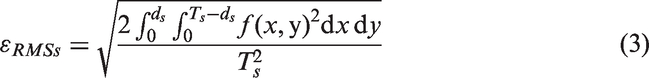


In addition, since the plain weave fabric is one of the most common structure fabrics used for textile antenna substrate no matter whether there exits the stitching or not, it is necessary to correlate the surface roughness caused by the waviness from the plain weave structure itself with the antenna performance. The model representing a unit cell of plain weave structure was built shown in Figure 7. In Figure 7(a), the representative cell consists of four similar warp and weft yarns which were modeled as crimp cubes, and there were four protruding parts A, B, C and D on the ideal radiation surface in a representative cell of plain weave structure (see Figure 7(b)).The mentioned ideal radiation surface was set on the x–y plane with height of zero. Since the four parts were assumed to be the same, each part (e.g. Part A) could be chosen individually for model building. The sectional view of the plain weave fabric representative cell is illustrated in Figure 7(c), where Tp is the length of the cell, dp is the width of each yarn, and tp is the thickness of the fabric. The height of the rectangular yarn cross section hp obtained according to geometric relationship is tp/3.
(a) Three-dimensional model of a representative cell of plain weave structure. (b) Plan view of the representative model of plain weave structure. (c) Sectional view of part A of the representative cell.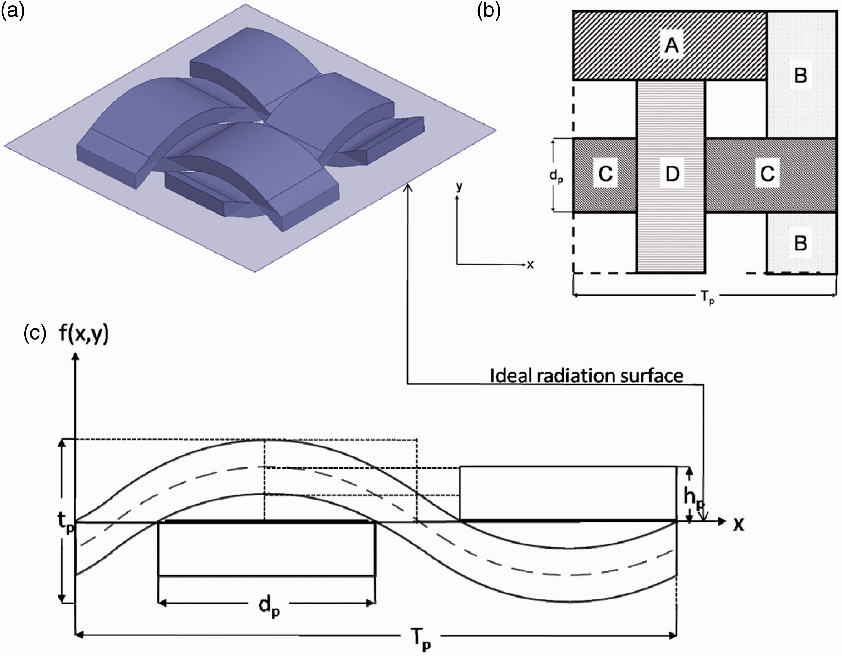
In accordance with the integration method in Figure 6, the RMS surface error of the plain weave structure was obtained in equation (4).


The acceptable accuracy of the antenna is related to the corresponding wavelength λ and an accuracy of λ/100 is usually considered adequate for most of the applications [18]. The shaded area plotted in Figure 8 shows the acceptable surface error of the antenna working at the highest frequency of 30 GHz. For our designed antenna with the stitched structure as the substrate, the operation frequency and the RMS surface error were 920 MHz and 0.25 mm, respectively, which dropped into the acceptable range shown as a square shape point in Figure 8 indicating this kind of stitched substrate was reliable and would lead to the proper antenna performance. Additionally, the round shape point in the shaded area in Figure 8 showed that the RMS surface error of 0.073 mm and frequency of 920 MHz would be also acceptable if the antenna substrate is the plain weave structure.
Acceptability evaluation of the antenna RMS surface error.
From the discussion above, the paired value of RMS surface error and working frequency is effective for estimating the textile antenna performance. At the same time, textile substrates with suitable structure parameters could be selected according to the antenna working frequency, which is more practical and direct in the real textile antenna design. Therefore, the relationships of the structure parameters including yarn thickness and density between critical frequencies were determined based on the models in Figures 5 and 7. Take the model of stitched structure in Figure 5 for example, the yarn thickness was the diameter of the sewing thread ds and the yarn density was obtained from the length of the stitch loop circle Ts. To calculate the critical frequency, one of the variants of yarn thickness or density was fixed in accord with real parameters and the other varied. The calculated results are shown in Figure 9. It can be seen in Figure 9(a) that if the yarn density was fixed, with the increase of yarn thickness, the critical frequency decreased because more errors in height direction were introduced resulting in the increase of the corresponding wavelength. As plotted in Figure 9(b), if the yarn thickness was fixed, the critical frequency decreased as the yarn density was increased because the increase of yarn connection results in the increase of surface roughness. The calculation of critical frequency of plain weave structure was similar to that of the stitched structure and the results showed similar trends. It is noted that yarn thickness is limited by yarn density, and thus the yarn thickness of plain weave structure in Figure 9(a) was not higher than 0.38 mm, which is due to the fixed yarn density of 22.47 cm−1.
The relationships between the critical frequency and (a) yarn thickness and (b) yarn density of the plain weave and stitched structure.
Conclusions
In this study, a textile dipole antenna was designed and fabricated aiming at working in the smart textiles area for short distance communication. The measured results showed that the antenna had good performance with the return loss value of −15.3 dB at the central frequency of 920 MHz and typical omnidirectional radiation patterns. To investigate the effect of textile substrate on the antenna performance, models for stitched and plain weave structures were built. The value of RMS surface error was calculated by integration method through these models, and the results were both in the acceptable range shown in the correlation plot between frequencies and RMS. In addition, to describe the direct fabric structure parameters, the relationships of yarn thickness and density with the critical frequencies were determined which gives the guideline for selecting the fabric as the substrate conveniently. The data and discussion on the effect of textile substrate in this paper provide new and enough basis for the area of smart textiles.
Footnotes
Declaration of Conflicting Interests
The author(s) declared no potential conflicts of interest with respect to the research, authorship, and/or publication of this article.
Funding
The author(s) disclosed receipt of the following financial support for the research, authorship, and/or publication of this article: This work was supported by the Natural Science Foundation for the Youth (no. 50803010), the Fundamental Research Funds for the Central Universities, the Shanghai Natural Science Foundation (no.14ZR1400100), and the Fundamental Research Funds for the Central Universities (no.CUSF-DH-D-2016013 and no. EG2016003).