
Abstract
With the evolution of the Internet of Things, stretchable antennas are playing an increasingly important role in wearable devices and flexible electronics. Typical drawbacks of current stretchable antennas are complex manufacturing processes, inadequate ventilation, and limited flexibility, which negatively impact their comfort and practicality. In this study, an all-knitted stretchable dipole antenna was designed and fabricated. This antenna was breathable and flexible like regular knitted fabric and had a simple manufacturing process. In addition, the effects of two yarn alignment types, namely antenna arms aligned in the course (AaC) and wale (AaW) directions, on antenna electromagnetic properties under tensile stress were investigated. Under unstretched conditions, both antenna AaC and AaW exhibited S11 of less than –10 dB at the operating frequency of 915 MHz, demonstrating good impedance matching performance and omnidirectional radiation characteristics. When stretched along the arm length direction, the frequency variations and strain of antenna AaC and AaW displayed strong linear relationships. Specifically, antenna AaC exhibited a higher sensitivity to the resonant frequency variation induced by strain when compared to antenna AaW. The results suggest that the antenna AaC are a more desirable option to be used as a sensor for human body movement monitoring. This study provides the theoretical basis and experimental foundation for the design and large-scale production of stretchable antennas utilizing textile materials.
With the rapid development of the Internet of Things (IoT) and smart wear, the demand for flexible electronics is becoming increasingly urgent. Taking advantage of flexible, lightweight, and high integration into garments, textile materials provide desirable wearing comfort in flexible electronics.1 –5 Textile-integrated electronics are not only widely used for monitoring human physiological signals, but also have the potential to detect variations in clothing properties as they are worn on the human body. For example, these devices can detect stress on the fabric during movement or contact friction between clothing and the human body when the fabric becomes wet with sweat. 6 Knitting, weaving, and embroidering are the most common textile manufacturing processes to form fully integrated textile electronics with conductive threads and conventional yarns. Among the various techniques, knitting is a one-step fabrication procedure that produces outstanding elasticity and seamless integration of the flexible electronic and the garment, providing desirable comfort to smart wear applications. The application areas are knitted electronics covered sensors,7 –10 memory elements, 11 energy harvesting platforms, 12 , 13 and radio frequency components. 14
The antenna is a radio frequency component that plays an important role in wireless communication and power transmission in wearable systems. Generally, wearable antennas are low-profile and consist of two main parts: the radiation element and the substrate, which are made of conductive and insulating materials, respectively.15 –17 The knitting technique allows the radiation element and substrate of the antenna to be fabricated simultaneously through a one-step procedure by using several yarns, showing an improvement in manufacturing efficiency and a higher level of integration than other textile antenna fabrication methods. Although plenty of textile antennas with knitted radiation elements or substrates have been reported,18 –20 research about one-step all-knitted antennas fabricated without glue or sewing thread remains limited.
All-knitted antennas are responsible for data communication and conveniently convert the measured mechanical signal into the electromagnetic signal as force-sensitive antennas, which have great potential in physiological and motion signal detection. In recent studies, a RFID (radio frequency identification) tag antenna fabricated with a silver-coated radiation element and a mix of wool and Lycra substrate was knitted into a tuck structure, showing desirable impedance matching performance around the center frequency of 870 MHz. The antenna was integrated into a bellyband and had been proven to be used for breathing monitoring.21 –23 Despite physiological signal monitoring being achieved by detecting the variation in electromagnetic properties caused by the antenna deformation under stress, the mechanical properties of stretchable antennas have been rarely measured and analyzed. Therefore, the investigation of mechanical properties of knitted antennas is crucial due to fabrics with different tensile properties exhibiting diverse strains under the same applied stress during wear.
Intarsia is a knitting technique developed for knitting patterns with multiple colors of yarn. It is conceivable that the intarsia technique also applies to all-knitted antenna fabrication, forming various shapes and sizes of radiation elements and substrate blocks with multiple yarn materials. Intarsia-knitted fabrics wrap different yarns around at the border of the blocks and leave no floats behind the loops, bringing about less yarn consumption and neat profiles of blocks, offering advantages in reducing the cost of conductive yarns and minimizing interference with antenna performance caused by floats.
In this study, an all-knitted antenna fabricated using the intarsia technique with an operating frequency of 915 MHz is proposed. The selected antenna type was a dipole with simple, symmetrical rectangular arms that were easy to fabricate. Since the dipole antenna was linearly polarized, the electromagnetic properties of the antenna were strongly influenced by the yarn arrangement within the antenna arms. 24 , 25 Therefore, the antenna had two alternating yarn alignment types, specifically antenna arms aligned in the course (AaC) and wale (AaW) directions. Simulation models with corresponding structures were constructed to optimize antenna sizes and predict the electromagnetic properties. Furthermore, the electromagnetic and tensile properties of both antenna yarn alignment types were investigated and compared, and the effects of stress and strain on antenna resonant frequencies were discussed.
Antenna structure, design, and fabrication
Antenna structure and modeling
The knitted dipole antenna consisted of two arms for radiating signals and a substrate for holding up the antenna arms. A schematic of the antenna is illustrated in Figure 1(a). The intarsia technique made the borders of the antenna arms and the substrate interlocked, left no floats behind the knitted loops, created neat profiles in both front and back views, and the stitches inside each block were knitted flat. The arms of the ordinary printed dipole antenna were rectangular with length of
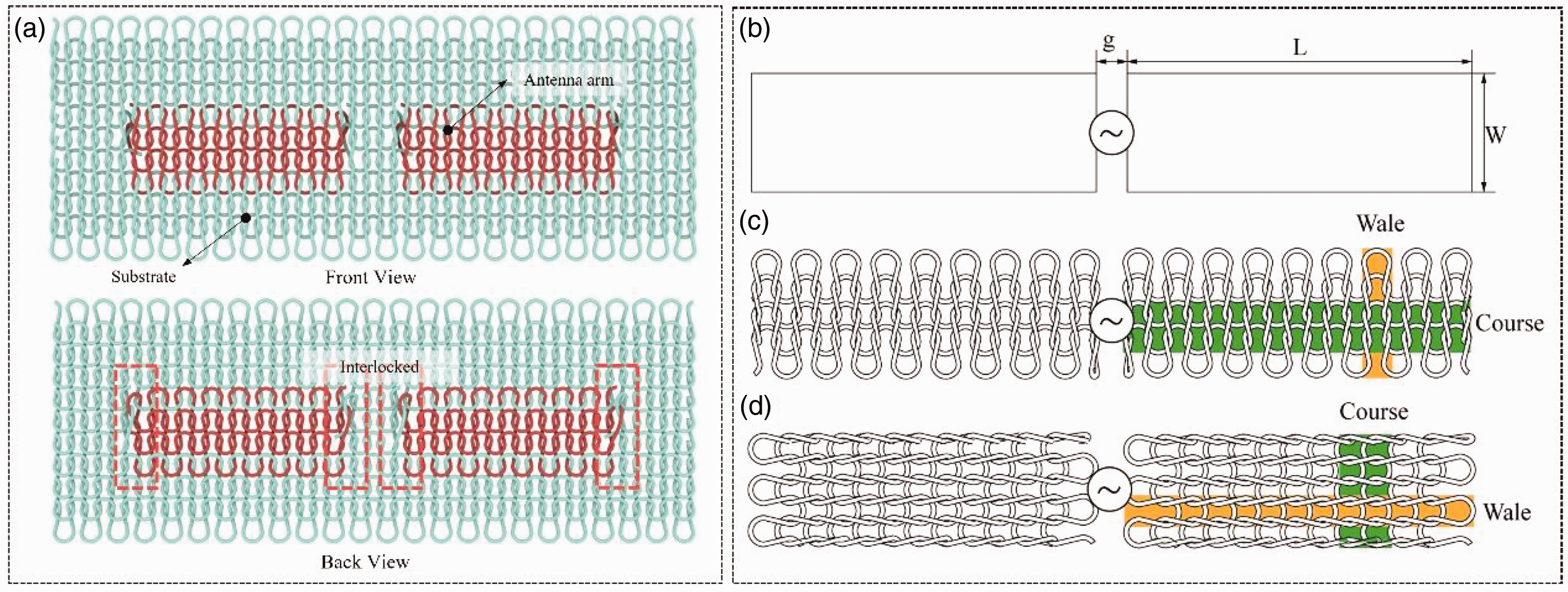
(a) Schematic of antenna knitted using the intarsia technique and configurations of the antenna arms. (b) Ordinary printed dipole antenna. (c) Knitted antenna arms aligned in the course direction and (d) Knitted antenna arms aligned in the wale direction.
The operating frequency λ of the proposed knitted antenna was set at 915 MHz. According to antenna theory, the resonant length (2l + g) of an ordinary dipole antenna is slightly less than half the wavelength of the operating frequency (λ/2). However, the knitted dipole antenna exhibited a big difference in size compared with the ordinary dipole antenna, despite achieving a similar operating frequency. This could be attributed to the curved antenna arm outlines and the hollow structure within the arms. To optimize the antenna size and predict the electromagnetic properties in the antenna design stage, solid models of antenna AaC and AaW were developed, as shown in Figure 2, for simulation.
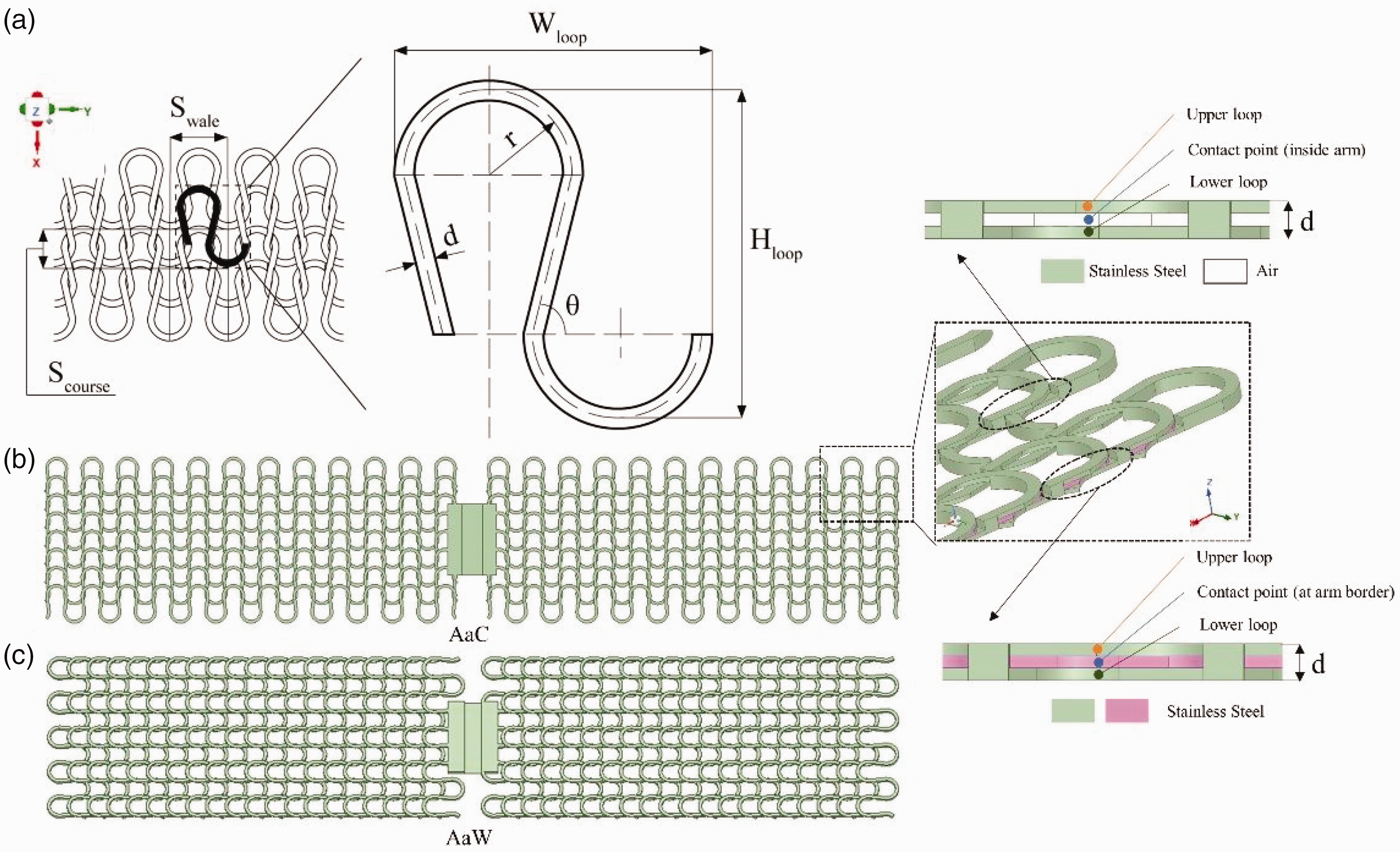
(a) Geometry of the knitted loop unit and simulation models of (b) antenna arms aligned in the course and (c) antenna arms aligned in the wale under stress of zero.
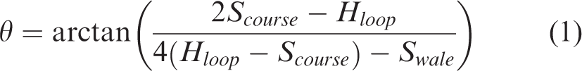
The geometry of the knitted loop unit in the simulation model is illustrated in Figure 2(a). The top arc and sinker arc of the knitted loop unit were simplified as semicircles, and the loop legs were simplified as straight segments. Descriptions of the feature parameters of the knitted loop unit are listed in Table 1. The values of
Descriptions of the feature parameters of the knitted loop unit
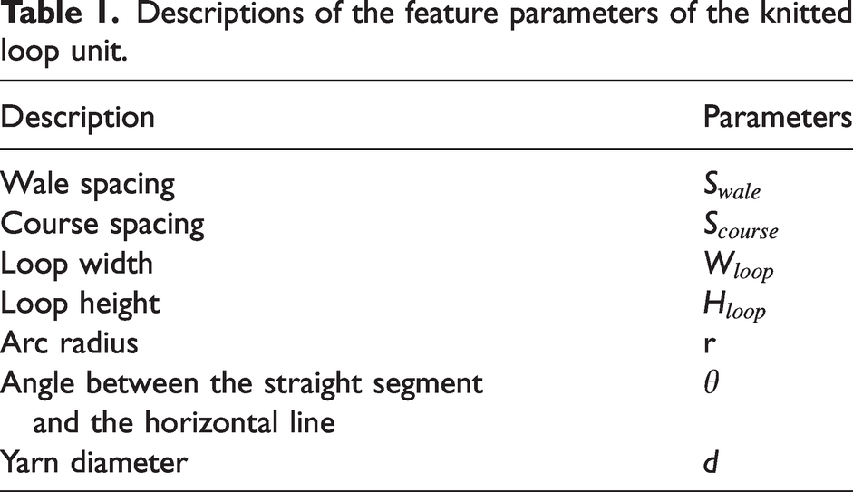
In this study, the diameter of the conductive yarn was 0.4 mm, the wale spacing was
Simulation models of antenna AaC and AaW were built as shown in Figures 2(b) and (c). The thickness of the solid models along the z-axis was set equal to the yarn diameter
Antenna design and fabrication
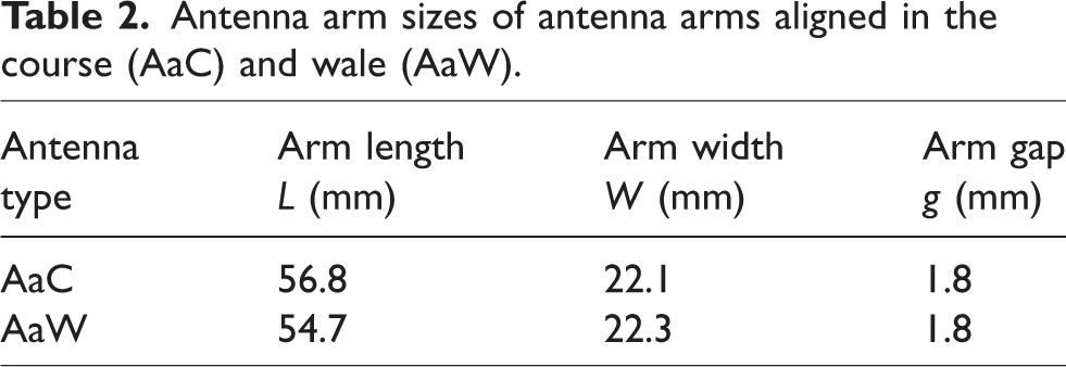
The size parameters of the antennas were obtained from the optimized simulated results; the arm sizes of antenna AaC and AaW were designed differently because of the diverse knitting structures, as listed in Table 2. The two arms of the antenna were embedded into the middle of the rectangular substrate with length and width of 200 and 100 mm, respectively. The antenna arms were made of stainless-steel yarn with count of 275 D/4 and conductivity of 7.24 Ω/m, while the substrate was made of polyester yarn with count of 150 D/16, dielectric constant of 1.9, and loss tangent of 4.5 × 10⁻³. The antenna samples were knitted by a flat weft knitting machine with a gauge of 5 (KH-868, Yunnei Textile Equipment FTY, Shanghai, China) and an intarsia carriage (KA-8210, Yunnei Textile Equipment FTY, Shanghai, China); the course and wale densities of the fabric were 1.98 and 3.90 stitches/cm, respectively. After the antenna arms and substrate were fabricated, a coaxial connector was connected to the antenna at the antenna arms, and the left and right antenna arms were connected to the inner conductor and outer conductor of the coaxial connector, respectively, for signal feeding. The fabricated samples of antenna AaC and AaW are shown in Figure 3.
Antenna arm sizes of antenna arms aligned in the course (AaC) and wale (AaW)
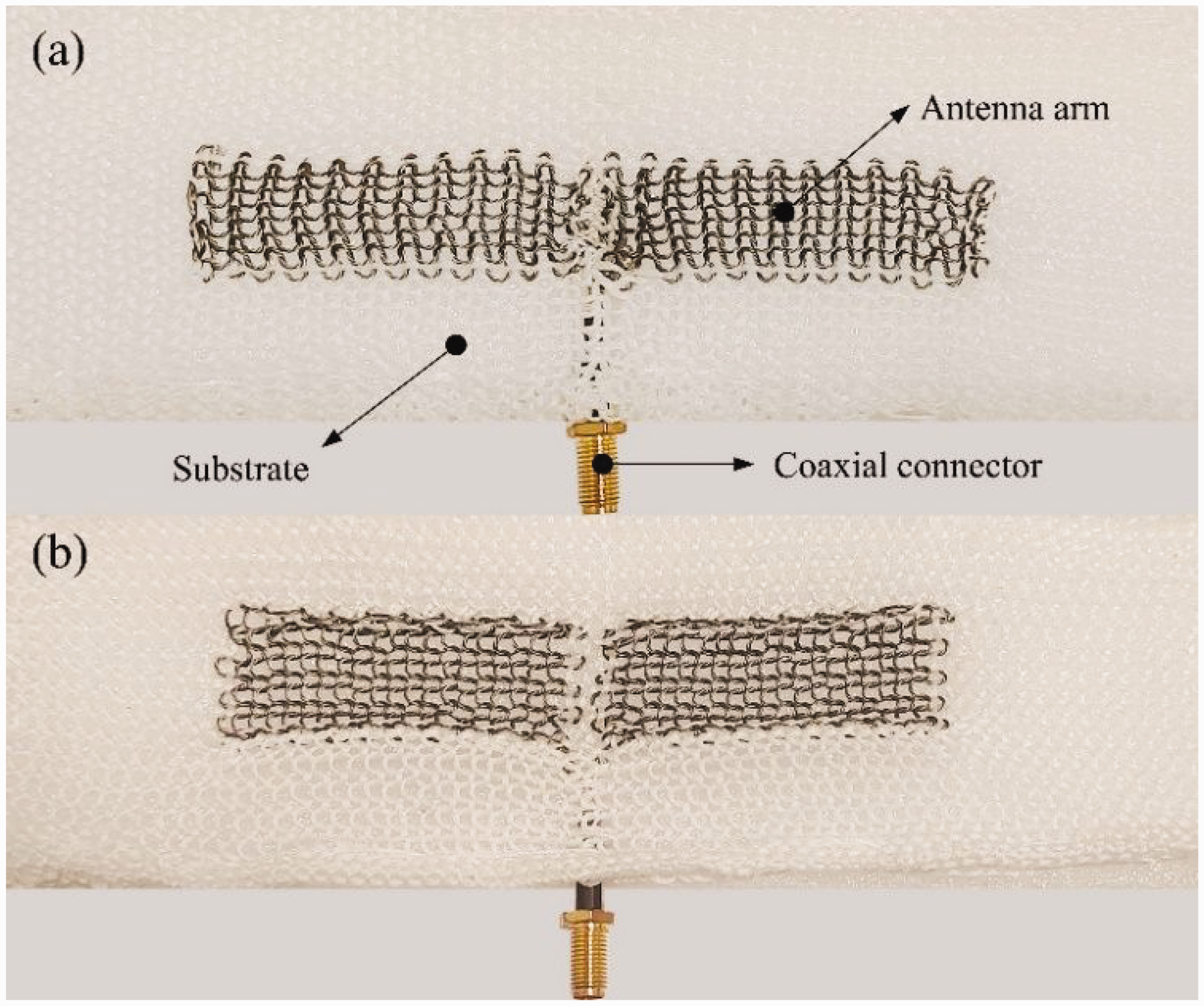
Photos of the knitted antenna (a) arms aligned in the course and (b) wale directions.
Antenna property measurements
Electromagnetic properties
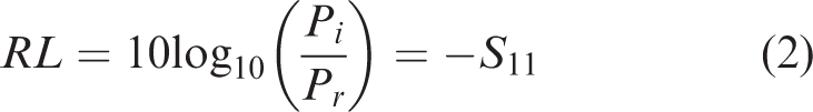
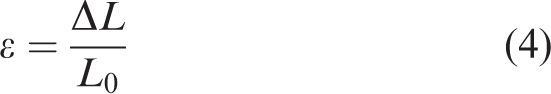
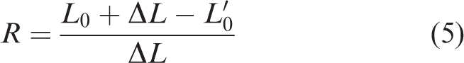
In this study, two essential electromagnetic properties of the antenna, namely return loss (RL) and radiation pattern, were measured. RL is one of the most important antenna properties that characterize antenna impedance matching; its expression in dB is as follows:
The radiation pattern characterizes the far-field radiation energy of an antenna in three-dimensional space; the E-plane pattern and the H-plane pattern are the most representative two-dimensional antenna radiation patterns, which parallel the electric field and magnetic field of the antenna, respectively. The radiation pattern was measured by using an antenna test system (AV9820TA, Shenzhen Yinjianglong Electronics Co., Ltd, Shenzhen, China) in a shielded chamber, which primarily consists of a vector network analyzer, a turn table, and a computer installed with a control and data storage system, as shown in Figure 4. The knitted antenna sample was fixed on a turn table and connected to one port of the vector network analyzer for signal reception, and a transmitting antenna was connected to the other port of the vector network analyzer for signal transmission. An expanded polyethylene board was placed behind the knitted dipole antenna as a support, and the centers of the transmitting antenna and the measured antenna were aligned. The E-plane pattern and H-plane pattern of the antenna were obtained by rotating the measured antenna samples from 0° to 360° with a step of 1°in the planes parallel to the electric and magnetic fields of the antenna. The radiation intensities at each angle received by the measured antenna were recorded, and the polar plots were plotted as radiation patterns.
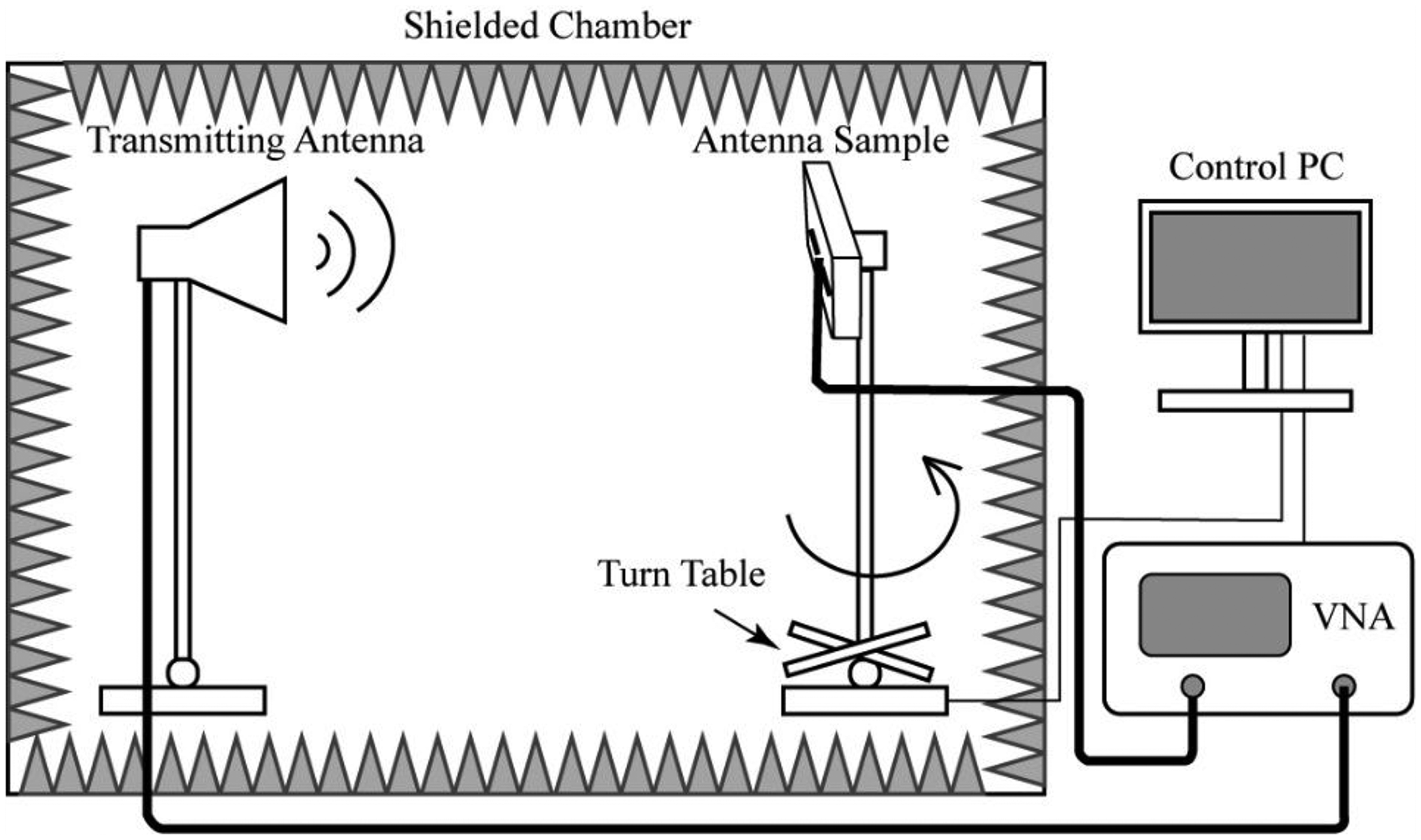
Schematics of the antenna radiation pattern test system. VNA: vector network analyzer.
Tensile properties
The tensile tests were conducted based on the standard FZ/T 70006-2004 “Stretch and recovery testing method for knits,” and an electronic fabric strength tester (YG026T-II, Ningbo Textile Instrument Factory, Zhejiang, China) was used. Three types of knitted fabrics, namely polyester fabric, stainless-steel fabric, and fabric with an antenna structure, were tested as illustrated in Figure 5. The knitting parameters and the yarn specifications were the same as those of the knitted stretchable dipole antennas introduced in the Antenna design and fabrication section. The fabric samples were knitted as 100 mm × 200 mm rectangles along the length (course parallel to the length direction) and width (wale parallel to the length direction) directions, respectively.

Schematics of the tensile test and samples: (a) polyester fabric; (b) stainless-steel fabric and (c) fabric with the antenna structure.
Two clamps, namely a fixed clamp and a moved clamp, with an original spacing distance of 100 mm between them, were used to hold and stretch the samples. A pretension of 1 N was applied to the samples before stretching. Then, the moved clamp went up at a speed of 100 mm/min until the pull force reached 70 N. After staying at the farthest place for 1 min, the moved clamp returned at a speed of 50 mm/min.
The pull force under stretch and the elongation of the fabric samples was recorded during the tests, and the values of stress 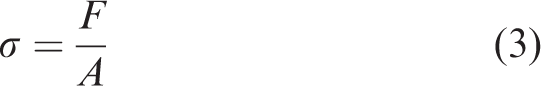
Results and discussion
Electromagnetic properties
As shown in Figure 6, the measured RL of both antenna AaC and AaW agreed well with the simulated results when stress was not applied. The measured –10 dB bandwidth of both antenna AaC (from 792 to 1169 MHz) and AaW (from 775 to 1074 MHz) fully covered the simulated bandwidth of AaC (from 821 to 1074 MHz) and AaW (from 795 to 1017 MHz). Both the measured and simulated results of antenna AaC and AaW exhibited good impedance matching performance at the operating frequency of 915 MHz, with S11 values lower than –10 dB. This verified the reliability of the all-knitted dipole antenna fabricated using the intarsia technique.
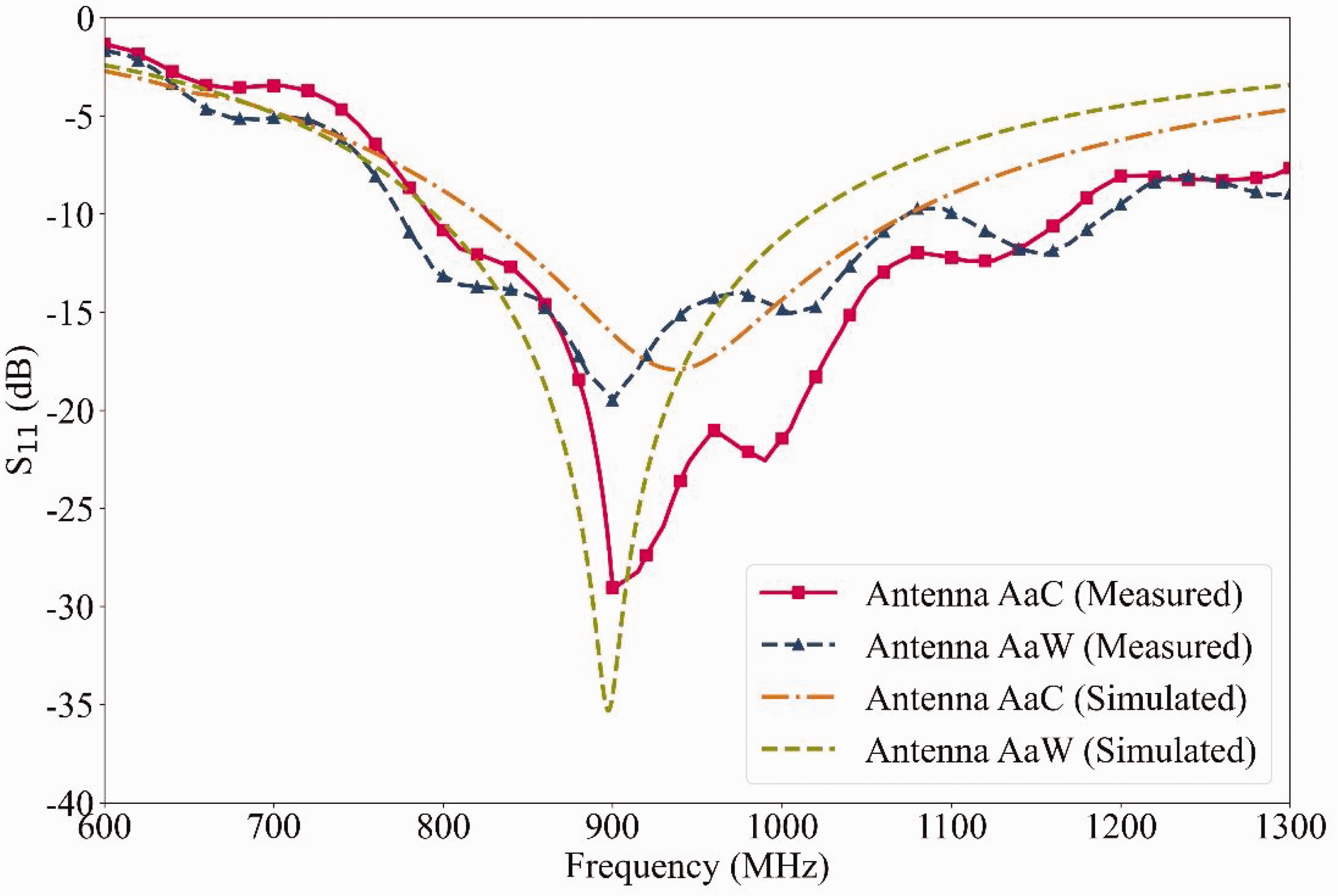
Simulated and measured return loss of the knitted antennas with no stress. AaC: arms aligned in the course direction; AaW: arms aligned in the wale direction.
Furthermore, antenna AaC had a lower S11 value in the resonant frequency and a wider –10 dB bandwidth than antenna AaW in accordance with the measured RL curves. This is because the conductive yarns of antenna AaC were continuous in the direction of current flow, namely the direction of the antenna arm length, leading to better impedance matching performance. In contrast, the conduction of electricity of antenna AaW in this direction relied on the contact between the conductive yarns, which had less conductivity and stability. In addition, two resonant frequencies around 915 MHz arose in the measured RL curve of antenna AaC due to the size error between the inner conductor and outer conductor of the coaxial probe that was manually connected to the antenna.
Figure 7 illustrates the simulated and measured radiation patterns of antenna AaC and AaW with no stress. Both two antennas exhibited omnidirectional radiating characteristics with a figure-eight shape in the E-plane and a circular shape in the H-plane. In addition, a clockwise rotation of approximately 20° was observed in the measured E-plane radiation pattern of the antenna AaW, with the minimum radiation strength showing at 109° and 293° in the plane. The observed discrepancy in radiation pattern between antenna AaW and AaC may be attributed to the lack of centrosymmetric structure in the two arms of antenna AaW. The manual production of the antenna samples likely introduced size errors that further amplified the imbalance in radiation power between the two antenna arms. In general, the radiation pattern skew problem of textile antennas could be improved by increasing the precision of the antenna samples.
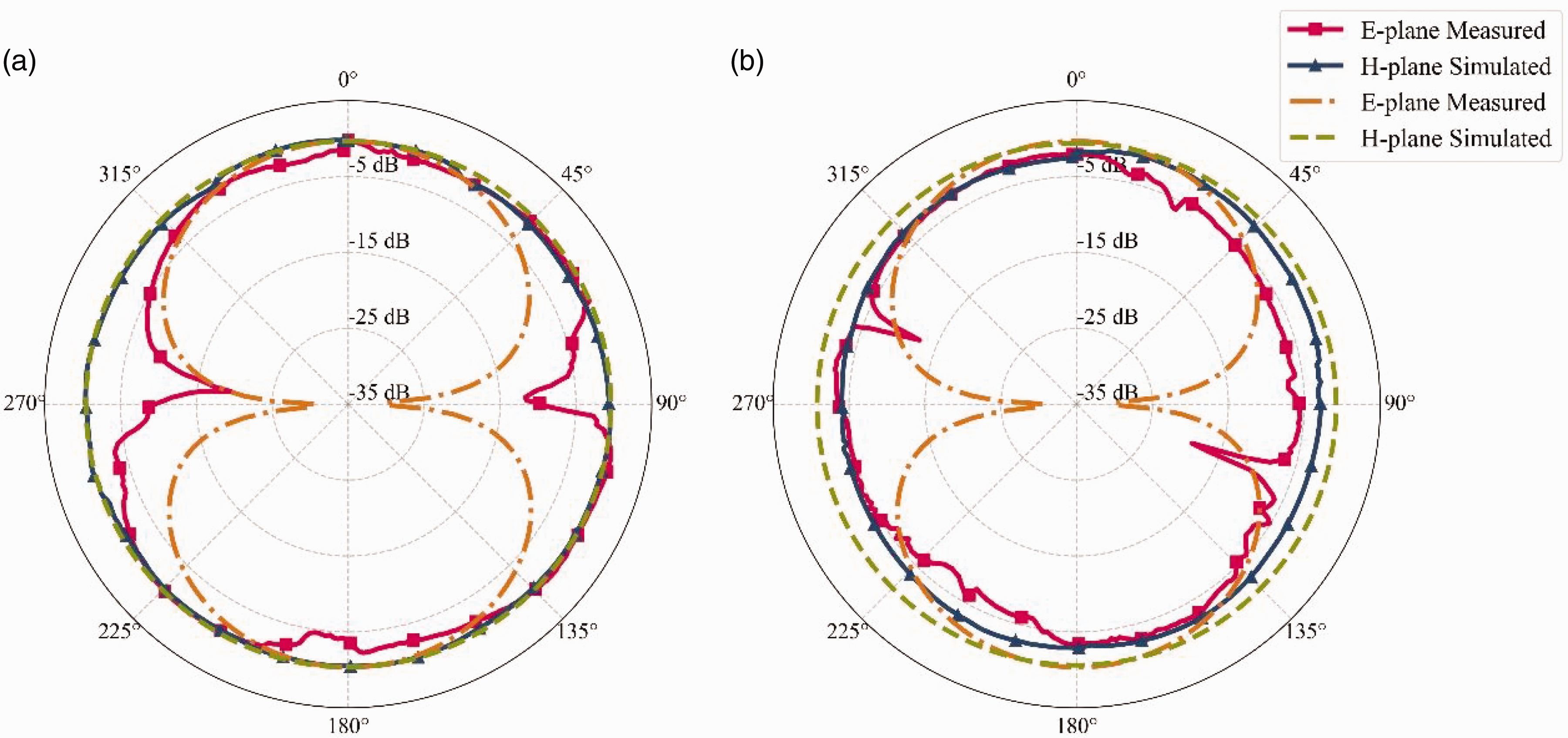
Simulated and measured radiation patterns of the knitted antenna (a) arms aligned in the course and (b) arms aligned in the wale with no stress.
Tensile properties
Figure 8 displays the stress–strain curves of polyester and stainless-steel fabrics, as well as the fabric with an antenna structure subjected to wale-wise and course-wise tensile stress. Figure 9 presents comparisons of the average strain and elastic recovery of the three fabric types under maximum stress of 0.58 MPa (pull force of 70 N) when stretched along the wale and course directions. The results indicate apparent differences in the tensile properties of each type of fabric under wale-wise and course-wise stress. Specifically, the fabrics exhibited a faster strain increase under increasing course-wise stress than wale-wise stress. Moreover, fabrics subjected to course-wise stress demonstrated larger strain and superior elastic recovery compared to those subjected to wale-wise stress. In addition, the fabric with an antenna structure exhibited equal or greater strain compared to polyester and stainless-steel fabrics under both wale-wise and course-wise stress. Specifically, under wale-wise stress, the fabric with an antenna structure displayed greater strain than the polyester and stainless-steel fabrics. Under course-wise stress, the fabric with an antenna structure showed similar strain to the polyester fabric but better extensibility compared to the stainless-steel fabric. The elastic recovery of the fabric with an antenna structure was intermediate between that of the polyester and stainless-steel fabrics. This can be attributed to the rigidity of the stainless-steel yarn in bending and its poor compressibility. When the stainless-steel yarn was combined with common yarns, such as polyester, bulges were formed in the stainless-steel embedded parts near the intersection of the two yarns, creating a wider space for the fabric with an antenna structure to elongate.
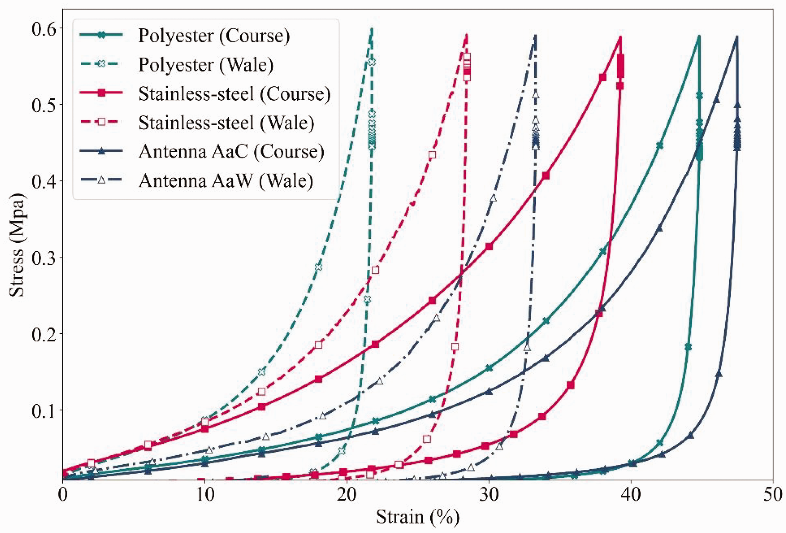
Stress–strain curves of polyester fabric, stainless-steel fabric, and fabric with an antenna structure under wale-wise and course-wise tensile stress.
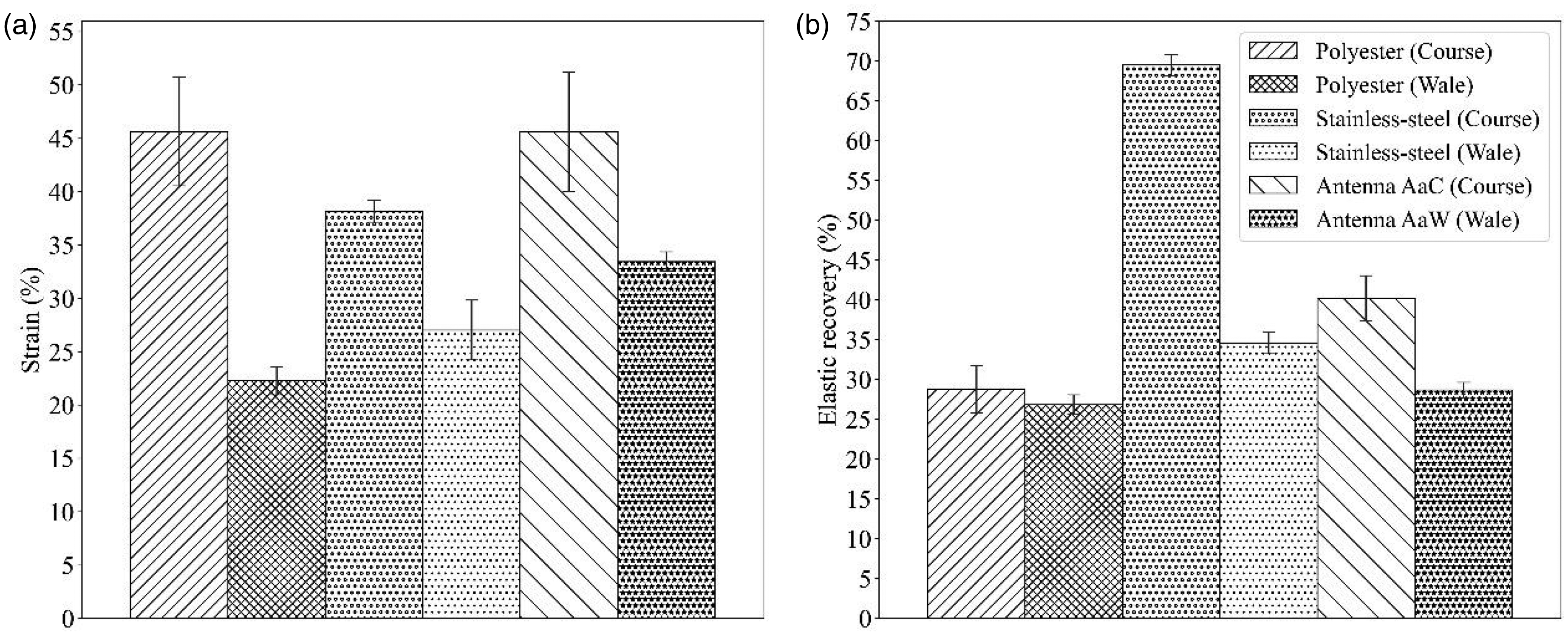
Average (a) strain and (b) elastic recovery of polyester fabric, stainless-steel fabric, and fabric with an antenna structure under a maximum stress of 0.58 MPa when stretched along the wale and course directions.
Effects of stress and strain on antenna resonant frequency
The tensile properties of an antenna can impact both its resonant frequency and radiation pattern, although the effect on the former is particularly significant. Moreover, if there is a linear relationship between the variation of tensile strain and resonant frequency, the antenna has the potential to be employed as an antenna sensor. Consequently, the focus is narrowed to the effect of the tensile properties of the antenna on its resonant frequency in this section.
The effects of stress and strain on antenna resonant frequency were investigated through simulation and measurement. To achieve a specific stress level in the antenna, the stress value was first converted to a strain value based on the stress–strain relationship depicted in Figure 8. With regard to measurement, the antenna was stretched to a predetermined strain level and fixed, and the corresponding stress and RL curve were recorded. In the case of simulation, the model size was adjusted to achieve the corresponding strain level and obtain the simulated RL curve. The widths of the antenna arms were assumed to remain constant in the simulation model, and the loop width and wale spacing increased when antenna AaC were stretched along the arm length direction:


In accordance with the results of the tensile tests, it can be inferred that stress has a more significant influence on the resonant frequency of antenna AaC compared to antenna AaW. This is due to the fact that antenna AaC exhibited a larger strain than antenna AaW at similar stress levels. For example, Figure 10 plots the simulated and measured RL of antenna AaC and AaW under stress levels of 0 and 0.17 MPa. The decreases in the simulated and measured resonant frequencies of antenna AaC were 61 and 57 MHz larger than those of antenna AaW, respectively, when the tensile stress increased from 0 to 0.17 MPa. This observation implies that antenna AaC are more sensitive to stress than antenna AaW.
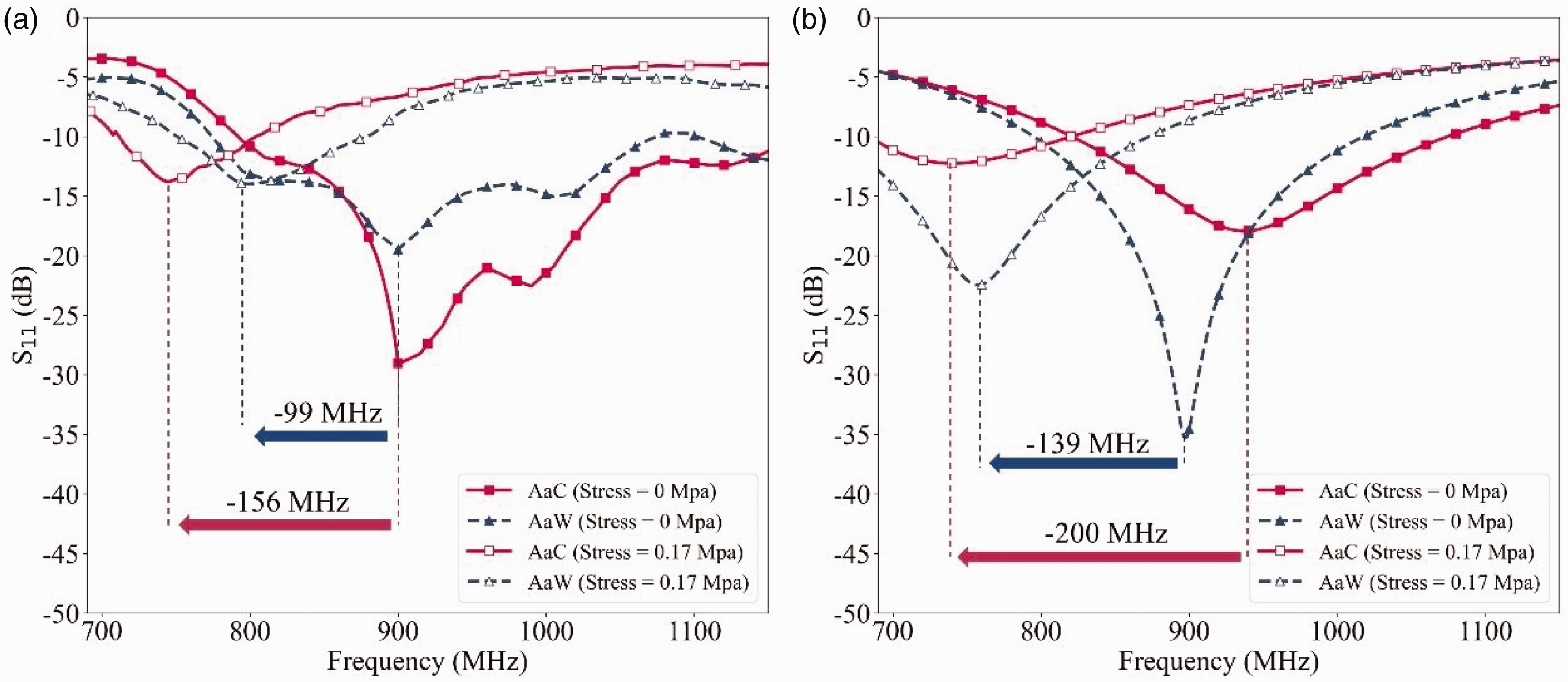
The (a) simulated and (b) measured return loss of antenna arms aligned in the course (AaC) and wale (AaW) under stress of 0 and 0.17 MPa.
The measurement and simulation procedures for antennas under specific strain are identical to those used for antennas under specific stress. Figure 11 plots the simulated and measured resonant frequency variations and S11 values of antenna AaC and AaW under strain levels from 0% to 30%. The relationships between the antenna resonant frequency variations and strain levels were fitted linearly. The correlation coefficients (R2) of the fitting lines obtained from the simulated results of antenna AaC and AaW were 0.9895 and 0.9951, respectively, indicating a strong linear relationship between resonant frequency variations and strain levels. The corresponding measured results presented slightly lower correlation coefficients of 0.9753 and 0.9551, indicating good agreement between simulation and measurement. The S11 values of both antenna AaC and AaW remained lower than –10 dB under strain levels from 0% to 30%, demonstrating that both antenna types maintained good impedance matching performances within the mentioned strain range. The linear trend and the stable impedance matching performance make the knitted antennas potentially effective strain sensors. Moreover, the slope of the fitting lines represents the sensitivity of the resonant frequency variation to strain. The simulated and measured sensitivities of antenna AaC were –4.3 and –6.15 MHz/
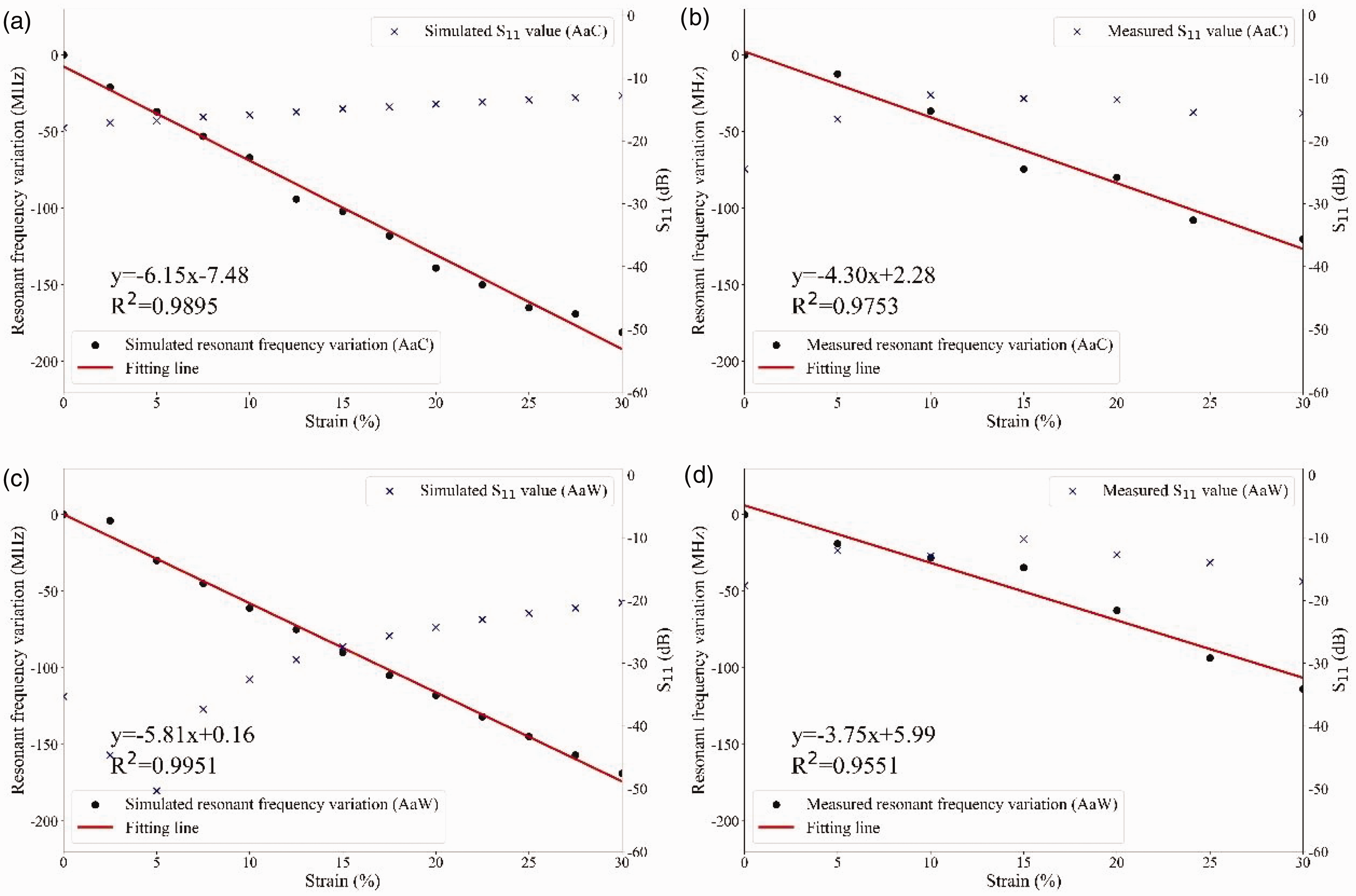
The resonant frequency variations and S11 values of antenna arms aligned in the course (AaC) and wale (AaW) under the strain level from 0 to 30%: (a) simulated antenna AaC; (b) measured antenna AaC; (c) simulated antenna AaW and (d) measured antenna AaW.
Conclusion
In this study, a knitted dipole antenna with a high level of fabric integration produced using the intarsia technique was proposed, and a solid simulation model for the antenna was established. Furthermore, the feasibility of the antenna was verified.
The electromagnetic and tensile properties of the antennas with two alternative yarn alignment types, namely antenna AaC and antenna AaW, were investigated. Both antenna AaC and AaW demonstrated good impedance matching performance at the operating frequency of 915 MHz. Although a higher level of skew was observed in the radiation patterns of antenna AaW, both antenna types exhibited typical omnidirectional radiation patterns, indicating their capability to transmit and receive signals at the operating frequency. When stress was applied to the antennas along the direction of the antenna arm length, antenna AaC deformed and recovered more easily than antenna AaW.
The effects of stress on antenna resonant frequency were investigated using linear regression analysis. The results indicated that the resonant frequency variations and strains of the antennas exhibited strong correlations, suggesting the potential for the antennas to serve as strain sensors. The size variation of antenna AaC was found to be more sensitive to stress, and the sensitivity of the resonant frequency variation to strain of antenna AaC was higher than that of antenna AaW. As a result, the structure of antenna AaW tended to provide a more stable performance under stress, while the structure of antenna AaC was more recommended for use as a strain sensor.
This study presents a high-efficiency production solution for textile-integrated antennas, provides a comprehensive analysis of the mechanical and electrical properties of stretchable antennas, and offers a theoretical basis and experimental foundation for the design and performance optimization of intarsia-knitted antennas. In further studies, the impact of complex forces on the electromagnetic properties of knitted antennas will be analyzed to improve antenna reliability. In addition, the effects of extreme environments such as sweat infiltration will also be studied.
Footnotes
Declaration of conflicting interests
The author(s) declared no potential conflicts of interest with respect to the research, authorship, and/or publication of this article.
Funding
The author(s) disclosed receipt of the following financial support for the research, authorship, and/or publication of this article: This work was supported by the Open Foundation of National and Local Joint Engineering Laboratory of RF Integration and Micro-Assembly Technology (KFJJ20230201), the Science Foundation of Zhejiang Sci-Tech University (ZSTU) (19072466-Y and 17072156-Y), the Zhejiang Sci-Tech University (ZSTU) Outstanding Youth Grant Program; the National Natural Science Foundation of China (no. 50803010 and No. 52003245), the Key Laboratory of Advanced Textile Materials and Manufacturing Technology (Zhejiang Sci-Tech University), the Ministry of Education, and the Zhejiang Provincial Key Laboratory of Fiber Materials and Manufacturing Technology (grant number 2019QN05).