
Abstract
The development of electric circuit fabrication on flexible polymer substrates has attracted a significant interest as a pathway to low-cost, comfortable movement, and large-area electronics among direct printing techniques. In this study, the inkjet printing technique was used as a simple method to chemically deposit silver nano and micro-particles (85–500 nm) to the polyester fabrics. It is done by the ejection of silver nitrate and ascorbic acid as a reducing agent to attain nano metals on the different weave patterns with different surface roughness to measure the conductivity variations. A four-contact method was used to measure the electrical conductivity of the deposited samples which is usually employed in the electrical assessment of films. COMSOL Multiphysics® modeling software is used in order to simulate the conductivity of printed silver tracks and finally the results of simulation and experimental works have been compared. The main purpose of this study is to evaluate the effect of surface roughness on the electrical conductivity of printed silver tracks.
Keywords
Introduction
Protection and aesthetics are the two common characteristics typically associated with textiles as clothing. Nevertheless, with the quickly altering needs of today’s consumers, a third characteristic is rising—that of “intelligence”—that is being integrated into fabrics to produce interactive or e-textiles [1]. The term electronic textiles, or e-textiles, are used to denote the class of fabric structures that integrate electronic elements with textiles and can sense the changes in its environment and respond to it. This new class of wearable electronic systems is being designed to meet new and innovative applications in the military, public safety, healthcare, space exploration, sports, and consumer fitness fields.
Based on the manner of response, these materials can be divided into three categories [2]:
Passive smart materials: only sense the environmental conditions or stimuli. Active smart materials: sense and react to the conditions or stimuli. Very smart materials: sense, react and adapt with the changes accordingly.
Consequently, three components may be present in such materials, such as sensors, actuators, and controlling units. The sensors provide a nerve system to detect signals; thus, in a passive smart material, the existence of sensors is essential. Carbon electrodes integrated into fabrics can be used to detect specific environmental or biomedical features such as oxygen, salinity, moisture, or contaminants [3] in which electromyography (EMG) is the proper example of this case [4].
The actuators act on the detected signal either directly or from a central control unit; together with the sensors, they are the essential elements for active smart materials. Even at higher levels, like very smart or intelligent materials, another kind of unit is essential, which works like the brain, with cognition, reasoning, and activating capacities. Such an active control is necessary for different applications related to human body which requires electronics in textiles that induced a new research field “e-textiles” [5].
The challenge of wearable computer researchers was how to link computer hardware to clothing. Steve Mann in the 1980s was the first pioneer in the experimental labs of Massachusetts Institute of Technology (MIT) who implemented this technology by attaching various kinds of electronic devices to garments [6]. Carrying heavy rigid boxes in inflexible areas with visible wires through the cloths is impractical for a daily use and causes users to be unsatisfied and making feel of uncomfortable. New techniques, such as using conductive yarns, have been developed to provide innovative soft textile interfaces which are highly acceptable to the end user [7]. The key elements for creating e-textiles are the use of electrically conductive fibers, yarns, or inks in which their signals can be sent consequently throughout the garment and other flexible segments such as sensors, actuators, or computer chips are embedded in the garment [8].
Conductive coating can be made by electroless plating [9], evaporative deposition [10], sputtering [11] (http://www.worldcat.org/search?q=au%3ACampbell%2C+Stephen+A.%2C&qt=hot_author), and printing. Conductive coating is formed by using conductive polymers such as polyaniline (PANI) [12], polypyrrole (PPy) [13], polythiophene (PT) [14], or using conductive ink which is created by adding electrically conductive materials, such as carbon (carbon nanotubes to introduce chemical sensing properties into textile materials [15]), grapheme [16], copper [17], silver [18], nickel, and gold to traditional printing inks. These specific inks with the suitable viscosity and surface tension can be printed onto various substrates to create electrically active patterns [19]. Companies such as Creative Materials Incorporated, DuPont, Methode Electronics Incorporated, Motson, and Think and Tinker Limited currently produce and sell conductive inks [20].
Among the highly mentioned conductive metals such as Ag (σ = 6.3 × 10⁷ S/m), Cu (σ = 5.96 × 10⁷ S/m), Au (σ = 4.42 × 10⁷ S/m), and Al (σ = 3.78 × 10⁷ S/m), silver particles are preferred because of the highest electrical conductivity and resistance to oxidation. In nanoparticles-based inks, the metallic dispersion in the ink should be stable to aggregation and precipitation in order to obtain ink with reproducible performance [21]. Increasing the possibility for miniaturization of electronic elements because of reducing the dimensions of elements has amplified the demand of using silver nanoparticles in preparing conductive inks [22]. As the size of low-dimensional materials decreases to the nanometer size range, electronic, magnetic, optic, catalytic, and thermodynamic properties of the materials are significantly altered from those of either the bulk or a single molecule. Especially, metal nanoparticles have very unique properties which directly relate to their dimensions and to the fact that a large ratio of the atoms in the particle are in the surface of it [23].
Polymer composites containing nanosilver particles were printed with the inkjet method in order to obtain a line or “points” being electricity conductors or contacts in electronic assembly [24]. In 2008, one of the researches has been done based on thermal decomposition method for silver nanoparticles synthesized in order to use in inkjet application. This method is based on the decomposition of silver salt (silver alkanoate) of fatty acid at a high temperature in inert atmosphere. Silver salt is obtained as the result of the reaction of silver nitrate and fatty acid dissolved in sodium hydroxide water solution [25].
By thermal decomposition of silver alkanoate in nitrogen atmosphere at 250℃, stable silver nanoparticles with narrow size distribution could be obtained [26]. Recently, another reaction is suggested. In this technique, fatty acid dissolves in non-polar and slowly evaporates solvent (for example 1-octadecene) at 210℃ [27]. Both the reactions give silver powder composed of strongly aggregated ligand-stabilized AgNPs a with narrow size distribution. However, annealing temperature strongly affects the size of the final product and stabilization of nanoparticles in solvent [28]. Preparation silver ink requires dissolving of the synthesized silver powder in non-polar organic solvent (usually n-tetradecane). Tracks printed using such ink become conducive after sintering at 240–250℃ for 30 min [29]. Print quality and efficiency depend on the viscosity of the ink used. The best viscosity for inkjet applications is obtained 2.3–4.4 m Pa s [30].
Bidoki in 2007 used inkjet printing technique to chemically deposit silver nanoparticles (10–200 nm) simply by the ejecting silver nitrate [31] and reducing solutions onto the surface of a paper. In this way, he used a standard office inkjet thermal-head printer (300 dpi b ) and successfully formed deposited layers of silver with a high electrical conductance up to 1.89 × 10⁵ S/m and sheet resistance up to 0.5 Ω/sq [32]. He continued his research for printing silver patterns to work as circuit components like conductor, resistor, capacitor, and inductor on different substrates such as a sheet of paper, PET plastic film, and textile fabrics. Different levels of conductivity were achieved simply by changing the printing sequence, inks ratio, and concentration. The highest level of conductivity achieved was 5.54 × 10⁵ S/m on paper [33].
In this study, the inkjet printing technique was used to chemically deposit silver particles on the different weave patterns with different surface roughnesses to measure the conductivity variations. Regarding the inaccessible theoretical model or simulation related to evaluating the effect of weave pattern on the final conductivity which is obtained by deposition of metal particles, several simulation software have been evaluated and finally COMSOL Multiphysics® modeling software has been chosen as proper software for this case. By applying this software, the effect of roughness on the electrical conductivity of printed silver tracks has been evaluated. Finally, the experimental result is compared with the result of simulation data and the same trend is achieved. Therefore, this research introduces a good evaluating method for finding the proper characteristic of woven fabric for producing the smart textile.
Experimental details
Chemicals
Both ascorbic acid and silver nitrate were used as analytical grade chemicals (99.5% purity, Merck). Different substrates were used in the inkjet metal deposition experiments; these included fabrics with various weave patterns made up of 100% polyester (an absorbency value is 0.2–0.5% [34]) which were obtained locally (Yazd University, Yazd).
The structure of woven fabrics
As can be seen in Figure 1, each pattern with the considered yarn density creates a specific roughness on the surface of fabric. For the investigation of printed conductivity in woven fabrics with different surface roughness, we have varied the pattern of these fabrics. There is no doubt that this parameter will change the roughness of surfaces which cause variation in the final electrical conductivity of coated nanosilver particles on these surfaces.
The effect of weave pattern on the surface roughness of fabric.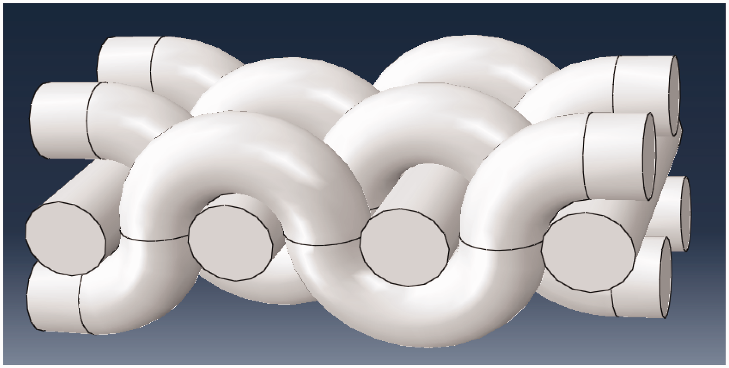
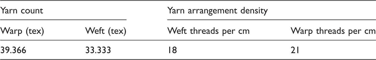
The specification of yarns which has been used.
The characteristic of produced fabrics with different patterns.

Printing method
For making conductive lines on the surface of fabrics, a digital printer (HP Deskjet 1280) has been used to print metallic salt and reduce agent solutions in separate runs. This printer is based on Drop on demand thermal inkjet printing technology and uses two ink cartridges that come in black and tri-color. Microsoft Word was employed as the print-controlling software. Normal speed and resolution for the black cartridge are 6 ppm and 600 × 600 dpi, respectively, and the paper size is “Letter”. Available inkjet printers have droplet volumes ranging from 2 to 40 picolitres depending on the nozzle size and the driving force. Ejected droplets spread on the surface by ∼20–200 µm, depending on the droplet volume and the wettability of the surface [31]. Due to simple structure for filling the cartridges with the ink in thermal inkjet printers, we preferred to use these heads instead of piezo-based types that have a greater range of ink compatibility [35].
According to previous experiments, silver nitrate (99.5% purity, Merck) is the metal salt of choice, and for reducing solution, ascorbic acid is selected.
The main purpose of this research is to deliver aqueous metal salt solution and aqueous solution of reducing agents by using inkjet technology in order to print highly conductive patterns with a good adhesion and good resolution on surface of fabrics with different surface roughnesses.
In the related literature, usually the substrate was first printed by reducing ink. Next, after an intermediate drying at room temperature for 5 min, silver nitrate solution was overprinted to achieve the higher conductivity on the substrate. Metal formation occurred in situ as a consequence of the redox reaction between reducing agent and metal salt solutions leaving metallic layers composed of aggregated metal particles. It is necessary to replicate the printing sequence more than once to attain connectivity between the metallic particles formed on the surface. It is noticeable to have intermediate drying process at room temperature between these runs to decrease the effect of printer leading rollers and holders on the final quality. The thickness of the deposited layer may be increased by repeating the inkjet deposition cycle [31]. Treatment had been done after printing process in order to achieve conductive tracks. The homogeneous surface of printed silver traces changes into the locally crystallized structure after the heat treatment [36]. This is because of rapid evaporation of solvent which limits the movement of silver particles, and results in a localized crystal growth. To form a conductive printed pattern, conductive particles must be sintered to create continuous connectivity and thus percolated paths [21].
The optimum quantity for each effective factor in printing process.

Taking into account the concentration of each ink and the output of each printing head (5.4 g m−2 silver nitrate ink and 5.8 g m−2 ascorbic acid ink), the achieved results for the requested number of printing layers reveal almost twice molar consumption of ascorbic acid compared with silver nitrate (2:1, respectively) for attaining the highest level of conductivity which completely matches the described redox reaction between these two materials [38]. SEM technique was used to investigate the morphology of the deposited pattern. As it is clearly visible (in the highly magnified image), the inkjet deposition process has been capable of producing nanosized silver particles ranging from 85 to 500 nm on the substrate (Figure 2).
SEM images from the morphology of the deposited pattern on the surface of sample 2 with the optimum considered setting in printing.
A sample of printed fabric is shown in Figure 3.
The result of conductive printing with the optimum considered setting for sample 4.
It is obvious that the fabrics used in the printing process have different roughness values in warp and weft direction (caused by different count and density of warp and weft yarns and the fabric pattern). Therefore, the printing process is considered in weft direction for all samples.
Measurements
Conductivity
Since the printed layers are designed to be conductive, it is required to execute experiments using the appropriate equipment in order to obtain applicable measurements. A four-contact method (Figure 4) is used to measure the electrical conductivity of the deposited strip layers. This method is usually employed in the electrical assessment of films [39].
The scheme of four-probe method for measuring film resistance.
For this measurement, four-contact-probe holder is positioned over the printed surface. The holder is fabricated with four copper probes which could make contact with the surface of each sample. To keep away from any gap between probes and the printed surfaces, a weight of 500 g was placed over the probes’ holder to press them against the printed surface. Then by supplying a constant current of 100 mA to the outer probes, the voltage between the inner probes is measured using a voltmeter. To minimize measurement errors mainly caused by inconsistent contact between the copper probes and the printed surfaces, each sample was tested three times and the average value was used in conductivity calculations. In this way, an average value of resistivity over the entire width of the film strip is obtained [31].
The electrical conductivity (σ) is a measure of how well it passes electrical current and may be determined by the resistivity (ρ) which is the inverse of conductivity.
Resistivity is determined through the following relationship:

The definite sample length applied in the resistance calculations is 20 mm which is the distance between the two inner probes of the four-contact device.
The thicknesses of the deposited metallic layers are measured using the cross-sectional SEM image. By using this method, the mean value of particle diameters is measured and finally based on the estimated particle numbers in printed layer; the thickness of layer is reported for all weave patterns.
Measured conductivity of fabrics with different patterns.

The results show that the conductivity of printed silver particles is less than silver wire. Conductivity will arise when metallic contact between the particles is present, and a continuous percolating network is formed throughout the printed feature.
A trend of obtained result between considered samples is shown in Figure 5.
A trend of obtained result between considered samples in experimental process.
Simulation of conductivity
Regarding the unavailable model or simulation relevant to the effect of roughness on the final conductivity of metal particles, the total search between proper simulation software for this case has been done and finally COMSOL Multiphysics® modeling software has been chosen. This software is a multipurpose software platform for modeling and simulating physics-based phenomena, such as electrical conductivity. COMSOL Multiphysics® is based on advanced numerical methods (finite element method (FEM)). Consequently, by applying this software, the effect of roughness on the electrical conductivity of printed silver tracks has been evaluated.
Some assumptions have been considered for simplicity as follows:
All the considered yarns have the same dimension.
Based on the software limitation and also in order to consider the effect of weave pattern and omit the other influenced factors such as the effect of particle arrangements on the final conductivity, the considered diameter for silver spheres is the same as yarn diameter and all particles have the same dimension. In order to evaluate the effect of weave pattern in final conductivity, we have to omit the other influenced factors such as particle arrangements which are completely random in the real station (in experimental section) for all the weave patterns and the particles are deposited on the surface of weave patterns by considering sliding phenomena in pores. Warp crimp of all patterns has been ignored. The space between yarns has been ignored as in our experiments; we have chosen a high density to reach the conductivity.
In the first step, we have plotted three-dimensional geometry of considered patterns with the same surface area.
As in the experimental section, the volume of droplets is about 40 picolitres and the diameter of yarns is about 500 µm, we can consider the same radius (1 mm) for yarns and silver spheres in this simulation (Figure 6).
Process of drawing three-dimensional geometry of sample 1.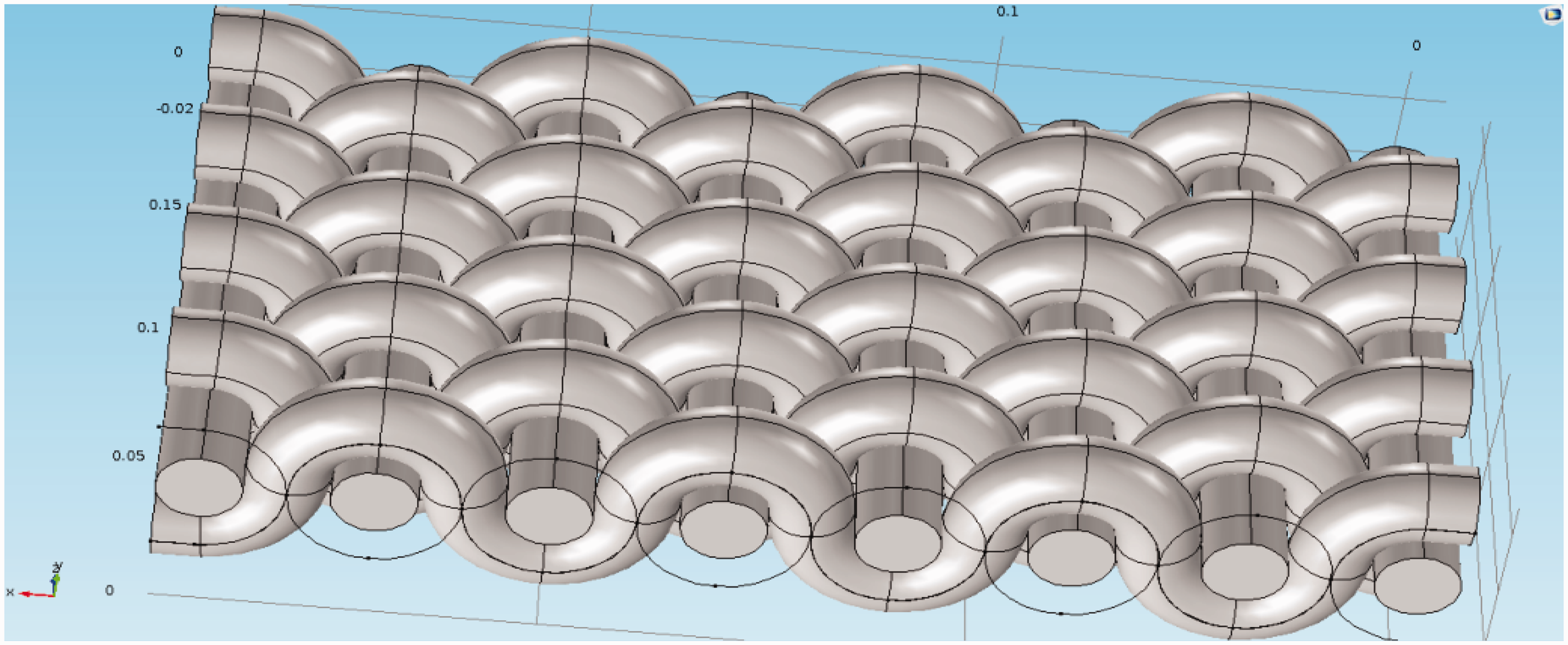
In the second step, we have used the same number of spherical particles to be deposited on those surfaces.
In this software, all physical and electrical properties of different material are located in its library and we have assigned silver material for deposited particles. Moreover, weft and warp yarns are considered as an insulator material (Figures 7).
Process of spherical silver particles deposition on the three- dimensional surface of sample 1.
In the third step, we have made mesh for deposited particles in order to make a boundary conditions and the interparticle distance. For mesh setting, we have considered the fine mesh. In this simulating, huge memory is required and the interparticle distance is in the range of 0.3–2.4 mm.
In the final step, we have considered the same electric potential difference (10 v) between deposited silver particles for each pattern and the total electrical current is determined by computing the surface integration of current density in three directions of Cartesian coordinates. Absolutely, each surface roughness makes special contact between particles which affects the final conductivity of that sample.
For a better understanding of the described final step in the simulation process, see Figure 8.
Process of computing electrical current which passes through the deposited silver particles on the surface of sample 1.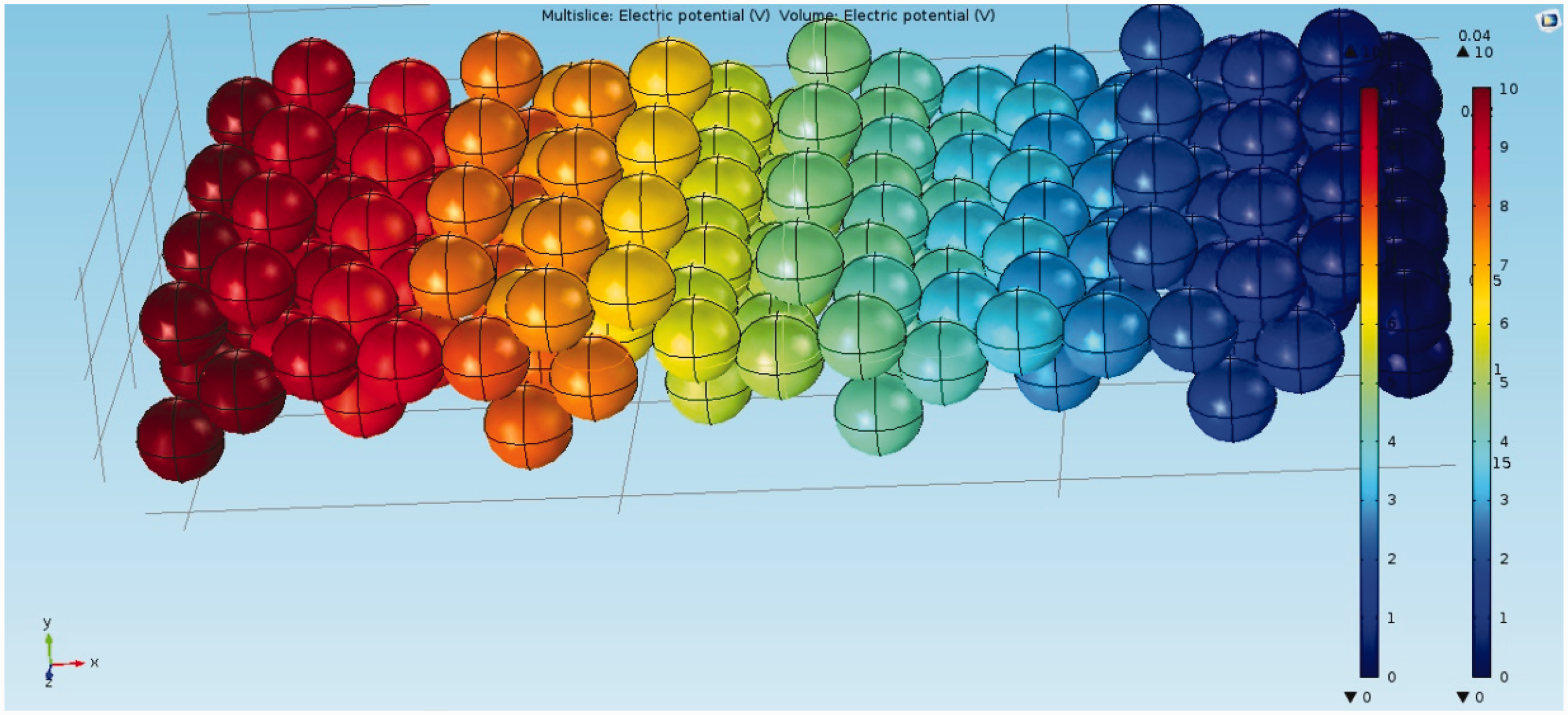
Measured conductivity of fabrics with different patterns.

As the results show, the amount of conductivities calculated in simulation is much bigger in comparison with experimental data. However, the trend of increasing or decreasing conductivity between considered patterns is the same.
The reason for the difference between experimental and simulation data related to the final conductivity is obvious because of considered spherical size for silver particles which is about 1000 times bigger than the real size in experimental work. As we aimed to evaluate the effect of pattern roughness on the final conductivity, the size of particles has been adjusted with the size of the yarn which will omit the effect of yarn roughness on the final conductivity. A trend of obtained result between considered samples is shown in Figure 9.
A trend of obtained result between considered samples in simulation process.
The relation between Experimental and simulation results is shown in Figure 10.
The relation between experimental and simulation results.
The best proper equation which is fitted with the diagram in Figure 10 is a polynomial equation with a regression number of R2 = 0.9101. Equation (1) shows a relation between experimental and simulation results:

Surface roughness
Fabric structural pattern characteristics are important parameters in fabric appearance uniformity and have an effective influence on the surface roughness which is an important part of mechanical comfort [41]. Figure 11 shows the effect of woven structure on the roughness of fabric surface:
Comparison of surface roughness between woven structures.
Handle is influenced by mechanical properties of textile fabrics and the surface roughness. The KES-F system is standard objectified method among different measurement methods which is a contact method and disturbs an accurate measurement for analysis of tactile perception. Therefore, we measure the surface roughness of textile fabrics without deformation by a non-contact method applied by the laser displacement sensor with a resolution of 2–120 µm and a linearity error ± 0.015 … ± 0.35 mm and a controlled linear motor which is highly precise for transferring at a constant speed.
Figure 12 shows a non-contact roughness measuring system that is composed of a laser displacement sensor with a high precision and linear motor. Laser displacement sensor measures the distance between textile fabrics and itself by using laser (distance sensor OADM 1216460/S35A). A beam of light with 0.5–0.9 mm diameter is projected from a laser diode to the object. The sensor used for the present study is capable of measuring the distance (and hence the height of the object) with a resolution of 2–120 µm [42]. The fabric sample is placed and fixed on a stage that is mounted on a linear motor. The stage is equipped with a linear motor and the whole system is interfaced with a microprocessor. In order to compensate for any undulation of the fabric, tensions are given on both ends of textile fabrics 20 gf/cm. The sensor measures the surface roughness over an 80-mm length along the warp and weft directions because the textile fabrics have the anisotropy. The sample moves with 0.1 mm per a 0.2 s and makes five sampling data from each point and the average is reported.
Schematic diagram of a non-contact roughness measuring system.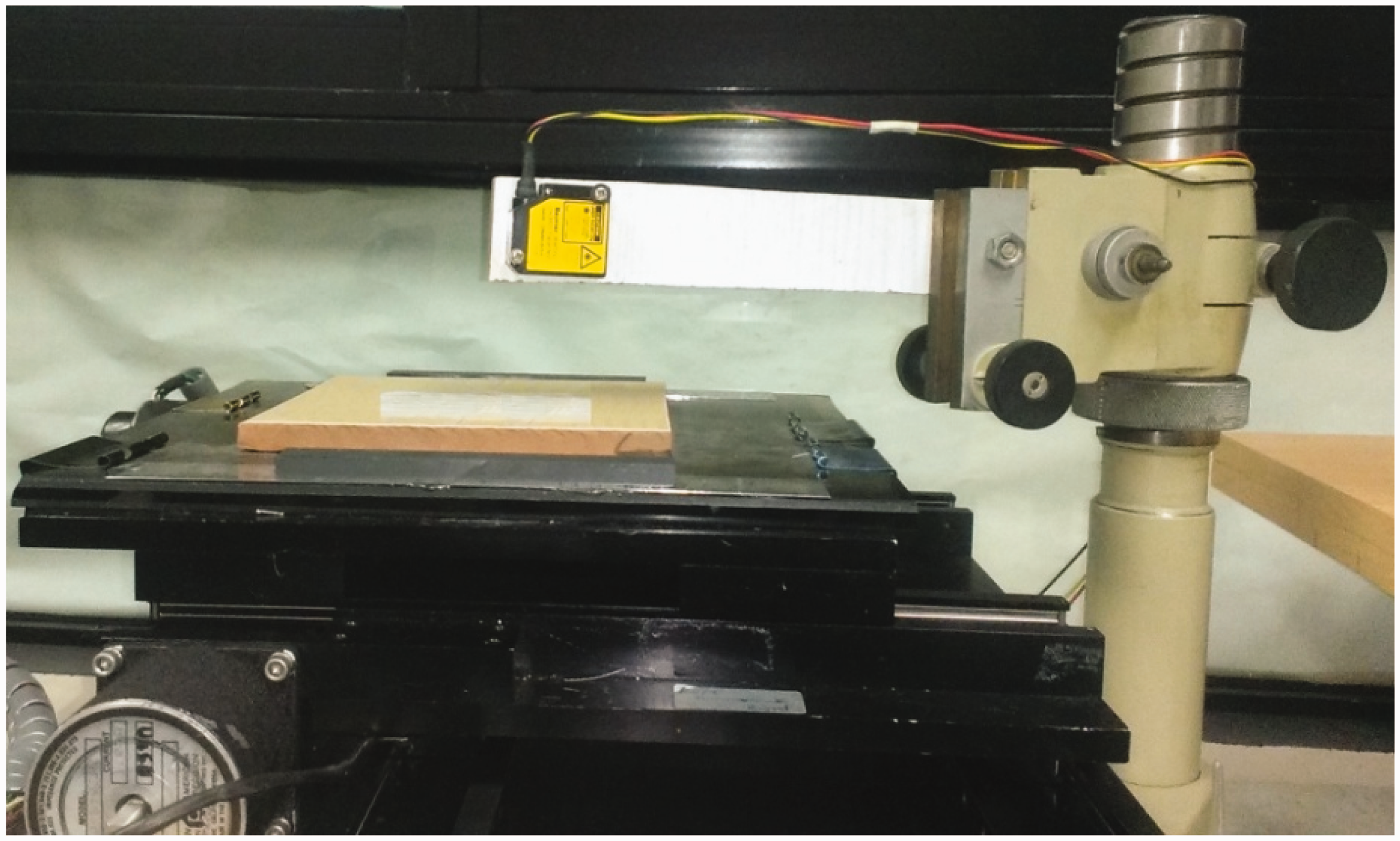
Based on the International Standard Organization (ISO 1997) and the Standard Number (4287), three parameters reflecting fabric surface roughness characteristics are shown in Figure 13, and are determined as follows: Rt: the distance between the maximum peak to the minimum valley.
Graphical representation of roughness parameters. Rc: mean of the profile peak heights for each sampling length of the assessed profile. Ra: the most useful and common parameter for analyzing the surface roughness. It is defined as the area between the roughness profile and its mean line, or the integral of the absolute value of the roughness profile height over the evaluation length.
It is described in the following equation:

In equation (3), L (mm) is the considered length of the sample for roughness measuring; Z(x) (mm) is the measured data in non-contact roughness measuring system from different positions of the considered length, d(x) (mm) is the amount of sample movement in the measurement steps.
Roughness parameters of produced fabrics with different patterns.

Results and discussions
Divisions of weave pattern effect on the surface roughness parameter (Ra) of samples.

Divisions of weave pattern effect on the surface roughness parameter (Rt) of samples.
Divisions of weave pattern effect on the surface roughness parameter (Rc) of samples.

The amount of Pvalue (probability factor) in this test is in 0.05 levels (if the amount of P is less than 0.05 with a confidence level of 95%, the effect of the related parameter will be significant). The mean square error in Table 7 is 0.001, in Table 8 is 3.235E − 006, and in Table 9 is 1.298E − 006.
When the effect of weave type is taken into consideration, according to the common weft setting values, it is generally possible to compare the surface roughness of fabrics with different weave structures. For example, it can be said that the rips fabrics are smoother than the plain weave structures. Decreasing yarn inter-sections in weave unit keeps the yarns closer to each other in contact points and this may cause decrease in roughness values.
The statistical analysis (analysis of variance (ANOVA)) results from the Duncan test for samples with different patterns in the experimental and also simulation investigation show that the effect of sample–structure–variation on the final electrical conductivity of silver particle printed tracks is significant.
Divisions of weave pattern effect on the electrical conductivity of samples in experimental method.

Divisions of weave pattern effect on the electrical conductivity of samples in simulation method.

The mean square error in Table 10 is 4760213.398 and in Table 11 is 378814654.140.
By considering the results of pattern effect on the roughness and electrical conductivity, we can obviously find the effect of roughness of surface on the final conductivity.
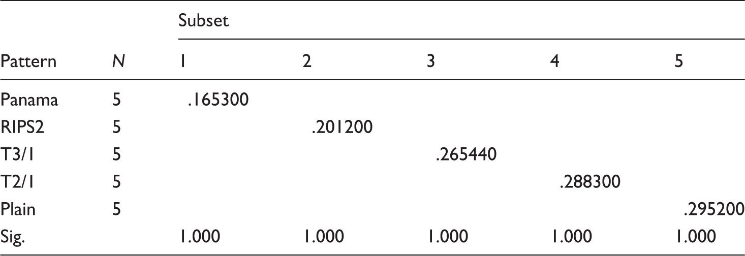
Divisions of roughness effect on the electrical conductivity of samples.

Consequently, by considering all the discussed matters and comparing woven structures, compact structure of plain woven fabric decreases the probability of metal particle penetration inside the woven structure which is needed for creating continuous percolating network throughout the printed feature. Moreover, based on the alternate interlacement of warp and weft threads, the reported Ra is higher than other structures, which means the longer path with the jagged shape in the same surface area of fabric. The created situation will allow more interparticle connection with the more contact area in comparison with the twill, panama, and rips structures. These phenomena result in the highest conductivity of plain fabrics between the mentioned patterns. The reason of resulted trend for the rest of weave patterns may follow the same idea.
Conclusion
Human research is going to develop artificial structures in order to make them smart, which mean that they can sense and react to environmental conditions or stimuli.
Smart textile is a new issue whose application is vast in different fields. Its benefits attract most of research concerns. Most of innovations and developments which have been done till now are going to continue and we are hopeful for the revolutionary changes in textile and human life by entering these products into the markets in order to have effective and wonderful roles in human’s daily life.
Using modern electronics and computer technologies in clothing brings more exciting possibilities for techno-textiles. Among the suggested methods in order to make E-textiles, inkjet process for depositing conductive inks on the surface of fabrics has been preferred.
In this regard, inkjet printing of metal salt solutions and reducing agents has been developed and deposited silver nanoparticles (85–500 nm) on the surface of paper and polyester fabric are performed. The deposited layers by this method showed a level of flexibility.
We can conclude from the results that conductivities of the prints are dependent on the surface roughness which is the result of weave pattern. The experimental result is compared with the results of simulation which is done by COMSOL Multiphysics® modeling software in order to evaluate the effect of surface roughness on the electrical conductivity of printed silver tracks. The results achieved by experimental and simulation methods show the same trend in final conductivity. This similarity confirms the effect of weave pattern on the final conductivity. Between considered samples with different patterns, plain fabric has the highest conductivity based on the compact structure and alternate interlacement of warp and weft threads which made continuous percolating network with more contact area by the deposited particles. The resulted conductivity of plain fabric is reported 0.285413 × 10⁶ S/m and the lowest conductivity obtained for panama pattern is 0.190246 × 10⁵ S/m whereas metallic silver wire has a conductivity of 6.173 × 10⁷ S/m. Therefore, plain fabric would be more proper for applying in smart fabrics by printing circuit on the surface of it.
Although the goal of this research was to expand the quality of digital and controllable printed conductive tracks by nanosilvers on the surface of flexible materials being appropriate for use in the electronic industry, continuing these research on other surfaces is essential.
Footnotes
Declaration of Conflicting Interests
The author(s) declared no potential conflicts of interest with respect to the research, authorship, and/or publication of this article.
Funding
The author(s) received no financial support for the research, authorship, and/or publication of this article.