
Abstract
In this paper, a novel textile antenna with a semi elliptical ground plane is designed for ultra-wideband applications. Conductive woven fabric made of stainless steel/polyester (80/20%) spun yarn with 158 Ω/m linear resistance is used to design the ground and the patch of antenna. Moreover, the warp density and weft density of woven fabric are selected in a way that it gets high value of surface conductivity. The surface conductivity of woven fabric was 0.088 Ω/sq. The proposed antenna is made of triangle patch within a transmission line and its dimensions are optimized using the genetic algorithm. Results show that the proposed antenna achieves multi impedance bandwidth ranging from 1.4 to 1.6 GHz, 1.8 to 2.4 GHz, and 3.4 to 11.6 GHz (reflection coefficient <−10 dB). The antenna in both bands from 1.4 to 1.6 GHz and 1.8 to 2.4 GHz is circularly polarized. This impedance bandwidth makes it appropriate for many wireless communication systems such as GPS, Wifi, PCS-1900, IMT-2000/UMTS, and ultra-wideband applications.
Keywords
Introduction
With the rapid development of wireless communication technologies, many researchers pay increasing attention to the study of wireless body area networks (WBANs). WBANs link various electronic devices in and on the human body. The application of WBANs is being expanded in medical services, national defense, wearable computing, and so on. Several frequency bands have been assigned for WBANs systems, such as the ultra-wideband (UWB: 3 ∼ 10 GHz) [1–3].
In wearable communication systems, UWB systems become more and more important in recent years owing to many potential applications. According to federal communications commission (FCC), UWB system is defined as any radio system operating within the band in 3.1–10.6 GHz [4,5]. As wearable computing develops, an increasing request for wireless wearable systems where the antenna has a decisive role on structure of them appears. For flexible antennas, textile materials can be interesting substrates because they are easily integrated into clothes [6,8]. In general, conductive textiles obtained by coating methods [9], conductive yarns [10–12], and conductive inks [13,14] can be used to made conductive parts of antenna, i.e. patch and ground. Sanjari et al. [7] studied the effect of compressive strain on the resonance frequency of wearable rectangular textile patch antenna. Zhu and Langley [9] proposed a dual-band wearable textile antenna on an electromagnetic band gap (EBG) substrate. In other words, EBG substrate is a periodic structure artificially engineered based on the photonic band-gap (PBG) phenomena in optics. The conductive material is a nylon fabric plated with copper and tin. Hertleer et al. [10] applied three different kinds of electronic textiles, i.e. FlecTron, Shieldit, and Super Zelt to design wearable microstrip patch antenna. The performance of spiral antenna printed on different fabrics was evaluated under displacement and deformation (bending and stretching) by Suh et al. [13]. Performance of screen printed textile antennas after repeated washing was studied by Kazani et al. [14]. A review of wearable antenna was presented by Rais et al. [15]. In this review, different types of wearable antennas, design methods, the analysis required for wearable antenna, etc. were described. In a few studies [16–18], some textile antennas for UWB application were designed. Conformal single-patch microstrip antenna integrated into three dimensional orthogonal woven fabrics was proposed by Yao and Qin [19]. Daya Murali et al. [20] designed microstrip rectangular patch antenna for medical applications using different cotton fabrics as substrate. The effect of conducting material type used in designing the radiating element and ground plane on performance of UWB wearable textile antenna was studied by El-basheer et al. [21]. Sankaralingam and Gupta [22] proposed textile antenna and investigated its performance in 2.45 GHz WLAN band under bent conditions. A light-weight and simple structure of monopole antenna using pure copper polyester taffeta fabric with 40 mm × 60 mm total dimension for body-centric wireless communications (BCWC) was proposed by Rahim et al. [23]. Salonen and Rahmat-Samii [24] studied the effect of antenna bending on input matching and impedance bandwidth. They studied three different antennas, namely, a conventional patch, EBG, and dual-band U-slot antennas. By merging the UWB technology with wearable textile technology, in this study, the novel textile antenna with circular polarization is designed and proposed. The proposed antenna is suitable to be used in various wireless applications including global positioning system (GPS) (1570.42–1580.42 MHz), PCS-1900 (1850–1990 MHz), IMT-2000/UMTS (1885–2200 MHz), WiFi (5800 MHz), and UWB (3.1–10.6 GHz). The proposed antenna is compact, simple, and easy to fabricate.
Textile materials
In this study, we produced the conductive woven fabric on shuttle weaving machine and it was used to make both patch and ground of antenna. The warp and weft density was 12.5 and 17 yarns per centimeter, respectively. The stainless steel/polyester (80/20%) and spun yarn (produced by Xiamen JL-fiber science and technology Co. LTD, China) was used as warp and weft. The diameter of stainless steel fiber and polyester fiber was 12 µm and 11.54 µm, respectively. The average length of fiber was 38 mm. In Figure 1, the cross section of conductive yarn achieved by microtomy technique is shown. The motic microscope with 100 magnification was used to capture the image.
The cross section of conductive yarn [magnified: 100].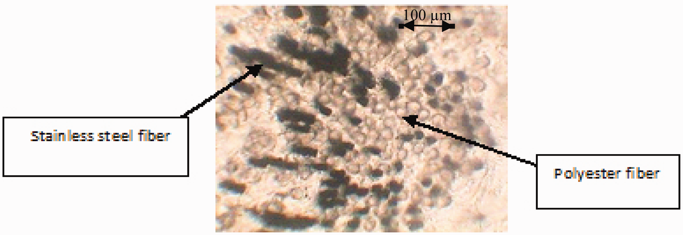
Properties of conductive yarn.

Note: Data in parenthesis are coefficient of variation (CV (%)).
Properties of conductive woven fabric.

Note: Data in parenthesis are coefficient of variation (CV (%)).
A needle-punched nonwoven polyester fabric was chosen as a textile substrate for antenna designing. Its thickness and weight were 2.50 mm and 578.80 g/m2, respectively, and its relative permittivity (ɛr) was 1.18. The patch and ground of antenna was adhered to substrate nonwoven fabric by inserting a very thin adhesion sheet affected by heat between them.
Antenna design and theory of microstrip antenna
Figure 2 shows the configuration of the proposed antenna. The length of equilateral triangular patch antenna (L), shown in Figure 2, can be calculated using equations (1) and (2), where c is the velocity of the light, Configuration of the proposed antenna. (a) Antenna patch, (b) antenna ground.
In this regard, at first the Se was obtained based on equation (1). Resonance frequency was 3 GHz because it is the lowest frequency of UWB and the relative permittivity (

The antenna appears as complex impedance (as per equation (3))


In order to have good antenna performance, radiation resistance should be increased but surface resistance should be decreased. According to equation (5), the surface impedance (Zs) depends on the surface resistance (Rs) in series with a surface resistance (Xs). On the other hand, based on equation (5), the surface impedance is affected by conductivity, vacuum permeability, and angular frequency.

A better antenna has a radiation resistance near 50 Ω and surface resistance near zero. In this regard, higher σ leads to the decrease of Rs resulting in the better performance of impedance matching.
The configuration and schematic of the proposed antenna is shown in Figure 2. As mentioned, the antenna is fabricated on needle-punched nonwoven polyester fabric as substrate in 80.0 mm × 70.0 mm dimensions. The proposed antenna has triangular shaped patch with length L which is fed by a microstrip line. The semi elliptical ground plane with dimensions Lg = 28.4 mm × Wg = 21.6 mm is adhered on the bottom side of the substrate. The length and width of the transmission line is fixed at Lt = 22 mm and Wt = 7.5 mm to have a 50 Ω impedance. To improve the bandwidth of the proposed antenna, the ground plane is modified by cutting square shaped notch with Ls = 5.0 mm × Ws = 5.0 mm dimensions. From the optimization of antenna parameters, it is found that the antenna is capable of tuning triple multiband from 1.4 to 1.6 GHz), 1.85 to 2.3 GHz, and 3.4 to 11.6 GHz with reflection coefficient less than −10 dB.
Parametric study
A parametric study is conducted to optimize the antenna parameters. All the parametric studies have been performed using high frequency simulation software (HFSS) from Ansoft. HFSS software is the three-dimensional (3D) full-wave electromagnetic fields based on the finite element method. In this research, we used the HFSS 13 version.
It can help to survey the effects of the different parameters on the impedance bandwidth. For optimization of antenna parameters, genetic algorithm is applied. In this process, the dimensions of antenna parameters, i.e. (L, Lt, Wf, Lg, Wg, Ls, and Ws) were optimized.
The strategy of the synthesis procedure is the minimization of the following function (equation (6))

Figures 3 to 5 show the effect of dimensions of antenna (H, H′, H″ = (L, Lt, Wf, Lg, Wg, Ls, and Ws)), Lt–Lg (the gap between length of transmission line and ground plane) and notch parameters on the reflection coefficient of designed antenna, respectively. According to Table 3, the dimensions of antenna, i.e. (L, Lt, Wf, Lg, Wg, Ls, and Ws)_ were changed in three levels. It is observed in Figure 3 that the decrease and increase of dimensions of different parts of the antenna from certain value lead to the decrease of the bandwidth. Therefore, the dimensions of the antenna in H level with a good impedance matching were considered as optimized ones and were taken into account for the optimization algorithm.
Effect of H parameters on the antenna reflection coefficient. Effect of notch on the antenna reflection coefficient. Variations of values for antenna dimensions.


Also, it can be observed that proposed antenna with H parameters including the Lt–Lg = 0.4 mm (as shown in Figure 4) and with notch (as shown in Figure 5) shows a good impedance matching and therefore these conditions were taken into account for the optimization algorithm.
Effect of gap width between triangular patch and ground plane (Lt–Lg) on reflection coefficient.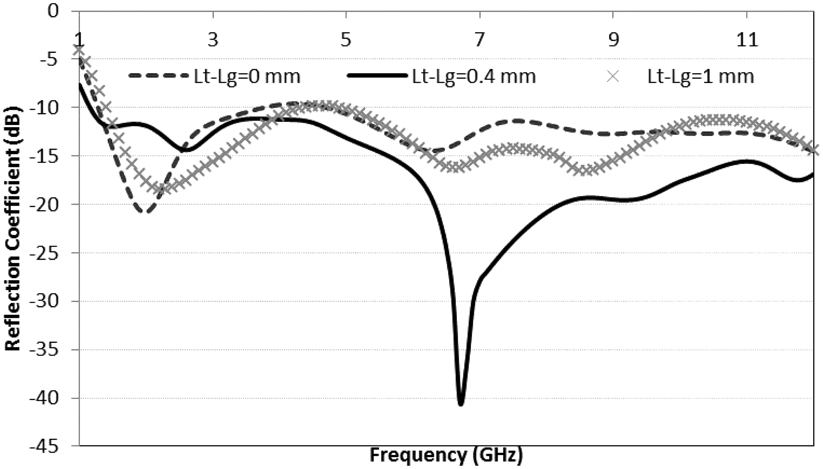
Results and discussion
The proposed antenna has been simulated by HFSS. A fabricated antenna with the optimized dimension (according to Table 3, H = (60.0 mm, 22.0 mm, 5.0 mm, 21.6 mm, 28.4 mm, 5.0 mm and 5.0 mm)) and the optimized structure is shown in Figure 6. The performance of antenna was measured in an anechoic chamber using far field antenna measurement system and vector network analyzer. The simulated and measured reflection coefficient of the proposed antenna is depicted in Figure.7. The results show that the measured impedance bandwidth of the proposed antenna covers the range from 1.4 to 1.6 GHz, 1.85 to 2.4 GHz, and 3.4 to 11.6 GHz. Moreover, the peak gain of the proposed antenna which is shown in Figure 8 reveals the good gain of antenna. The radiation efficiency of the proposed antenna with an average of 60% in the frequency range of interest is shown in Figure 9. The disparity between the measured and simulated results is attributed to manufacturing tolerance and imperfect soldering effect of the SMA connector and nonuniform distribution of the material properties on substrate. Another reason of the disparity could be the effect of the feeding cable, which has not been considered in simulation, as the antenna is physically small.
Photograph of the proposed antenna. (a) Antenna patch, (b) antenna ground. Measured and simulated reflection coefficient of the proposed antenna. Simulated gain of the proposed antenna. Radiation efficiency of the proposed antenna. Axial ratio of the proposed antenna.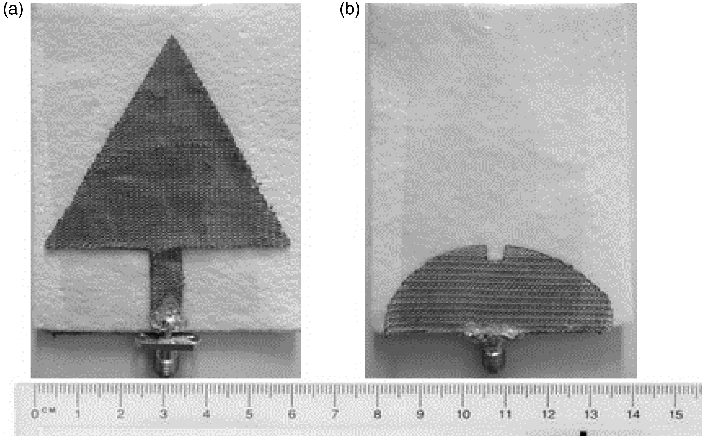


For GPS applications, the circular polarization is one of the most important antenna parameters. Further, the dimensions of the ground plane, i.e. P = (Wg;Lg) parameter, can play a key role in the kind of polarization; it means changing the dimensions of these parameters directly influence the polarization and it gradually changes the performance of the polarization. The optimized values for circular polarization are realized with P = (Wg = 2.84 mm; Lg = 2.16 mm) for fabrication of the proposed antenna. Figure 10 shows the simulation results of the proposed antenna with circular polarizations in the range of the frequency from 1 GHz to 3 GHz.
The radiation patterns of the proposed antenna at 1.5 GHz, 2.2 GHz, and 5.4 GHzs are shown in Figure 11. It is observed that E-plane patterns are almost omnidirectional with low cross polarization, but in higher frequencies and in the cross polar pattern, they gradually increase but in co-polar pattern are not omnidirectional.
Measured E and H-plane radiation patterns: (a) 1.45 GHz, b 2.2 GHz, c 5.8 GHz (Black line: co-polarized field, orange line: cross-polarized field).
Conclusion
In this study to develop a textile antenna, conductive woven fabric by using polyester/stainless steel (20/80%) staple fiber yarn was produced. The conductivity of yarn and structure of woven fabric was selected in a manner that suitable surface conductivity of woven fabric was obtained to be used as a material for designing the antenna. Afterwards, a novel textile antenna has been proposed and prototyped for ultra-wideband wireless applications. A design evolution and a parametric analysis with genetic algorithm are presented to provide information for designing, optimizing, and understanding the fundamental radiation mechanism of the proposed antenna. It is observed that the proposed antenna achieves multi bandwidth ranging from 1.4 to 1.6 GHz and 1.85 to 2.4 GHz with circular polarization in both bands and an ultra-wideband from 3.4 to 11.6 GHz. The proposed antenna is suitable for many applications such as GPS, PCS-1900, IMT-2000/UMTS, WiFi, and UWB bandwidth. In future, we aim to work on the effect of washing process and the human body sweat on performance of proposed textile antenna and also evaluate the effect of surface conductivity of woven fabric on performance of ultra-wideband textile antenna and we try to compare the effect of different structure of textiles such as weft knitted, nonwoven, and woven fabric on performance of textile antenna at different condition.
Footnotes
Declaration of Conflicting Interests
The author(s) declared no potential conflicts of interest with respect to the research, authorship, and/or publication of this article.
Funding
The author(s) disclosed receipt of the following financial support for the research, authorship, and/or publication of this article: This work was supported by the Islamic Azad University, Najafabad Branch.