
Abstract
This paper investigated the mechanical properties of GQ-6 subjected to a tremendous amount of uniaxial tests. Such material is a new kind of ultra high molecular weight polyethylene fiber and aimed to be adopted in stratospheric airship. To begin with, mono-uniaxial tensile tests were conducted. The cycling-uniaxial tensile experiments were then carried out on the basis of the mono-uniaxial tensile tests data. Finally, performances of welding seams were thoroughly investigated with forty welding specimens. Results of mono-uniaxial tensile tests revealed that such woven fabric possesses high tensile strength and low elongation ratio at break. Meanwhile, the stress–strain behaviors were fitted by the Ogden model and a good agreement between such model and experimental data was obtained. Influences of the uniaxial loading cycle on such woven stiffness were discussed and the elastic moduli were defined with a standard hysteresis loop. For the welding tests, four types of overlapping welding failures were discovered. Compared with intact specimens, an appropriate welding width of 60 mm and an approximate 15% discount of the ultimate tensile stress on the intact textile were obtained.
Keywords
Introduction
There has been an increasing interest in stratospheric airship as an alternative to traditional air vehicles for aerial exploiting and environmental monitoring. However, it is major developments in textile engineering that have been uniquely responsible for advances in airship design. Following the birth of airship [1], it was the rubber coated cotton fabric first applied in the early days. Then, the synthetic fibers replaced the natural rubber coating with a longer life. But such kind fabric still had a very limited strength. Up to date, the laminate materials, which can be sewed by the judicious selection of appropriate components, have been regarded as the most modern envelop materials. Compared to the common architectural textiles, the demands for the airship envelop fabric are more rigid and complex. As one of significant structural parts in an airship, membrane materials ideal for use in airship envelops would possess the following properties: high strength, high tear resistance, light weight, low creep, low permeability, reliable joints and resistance to environmental degradation through temperature, humidity and ultraviolet light, etc. Recently, the 46th Research Institute, 6th Academy of China Aerospace Science & Industry Corp. developed a new kind of woven fabrics, the GQ-6, for stratospheric airship envelope. However, mechanical properties on such new airship capsule materials are unclear.
In recent decades, tremendous efforts have been made to investigate the mechanical properties of various laminated fabrics. Mine [2] conducted a set of experiments with 48 polyester fabrics and found that fiber fineness and weave pattern were among the most important parameters which govern the total light reflectance from the fabric surfaces. Mine [3] also investigated the surface roughness of cotton woven fabrics and summarized that changes in yarn crimps, fabric balance and roughness of fabric surfaces were governed by different properties of yarns. Yang et al. [4] developed an integrated algorithm to study the wrinkling of membrane structure, in which the Newton-Raphson method and updated Lagrange formulation were adopted.
As for the long-term weathering characteristics of an envelope material, Nakahara [5] adopted specific doublers to such coated materials and testified to be effective. Yingying et al. [6] carried out the monotonous and cyclic loading tensile tests on textile and concluded that the tensile behaviors under cyclic loading are mainly related with stress amplitude, temperature and woven structure of substrate. A two year long outdoor exposure test was conducted on an envelop fabric utilized in Zylon stratospheric platform airship by Masaaki Nakadate [7]. They demonstrated tensile strength of the material after exposing to outdoor decreased significantly during hot and humid season of the second year as well as the first year, whereas decreased little in other seasons.
Apart from the aforementioned work, Kang et al. [8] performed uniaxial tensile tests to investigate the temperature effect on a developed laminated membrane material. Then the obtained tensile stiffness was compared with the nonlinear FEM analysis results and a good accordance was gotten. Chen et al. [9] carried out a series of uniaxial and biaxial tensile experiments to determine the mechanical properties of the envelope fabric Uretek3216A and found that the elastic constants should be determined for specific loading conditions due to its significant variation with the experimental protocols. Kilby [10] studied the effect of shear property on the buckling behavior of woven fabrics in both principal directions and more comprehensive researches at a random angle to the thread direction have been proposed by Zhaoqun Du [11] and Zhang et al. [12] Additionally, quantities of comparisons between the uniaxial and biaxial tests results on the fabric yarns have been performed. It is accepted by investigators [13, 14] that nonlinear biaxial characteristics were hard to be inferred from uniaxial experiments alone. Chen et al. [9] believed that the elastic constants should be determined for specific loading conditions and stress distributions depended on the practical project’s needs after comparing the two different axial experiments. However, they had to concede that the mechanical properties of envelop fabrics under biaxial tensile tests were more complicated to estimate accurately. Meanwhile, Ambroziak [15] showed that it was feasible to compare directly the consequences of uniaxial tests with biaxial tests for some laminated fabrics and demonstrated the advantages of uniaxial tests during preliminary design. However, the aforementioned studies mainly deal with the general material parameters such as the maximum tensile stress and the rupture strain ratio rather than the inner mechanism of woven fabrics. Additionally, to the author’s knowledge, few literatures pay attention to the welding performances of airship envelops.
In this paper, we aimed at studying the mechanical properties and the welding performance of a new coated fabric, the GQ-6, under uniaxial tensile tests. According to the airship demands on the capsule materials, the GQ-6 is manufactured by an ultra high molecular weight polyethylene fiber. Its surface finish is polyvinyl fluoride (PVF). It possesses pretty good UV protection capability. The permeability of such material is approximately less than 0.2 L/m2·24 h·0.1 Mpa. The average thickness of such woven fabrics is approximately 264 µm and the specified areal density is 170 g/m2. Firstly, mono-uniaxial tensile experiments were carried out and the relevant experimental data were achieved. The stress–strain behaviors of such woven fabrics were identified and processed thoroughly by the Ogden model. Then, cycling-uniaxial tests were conducted and the elastic modulus in each yarn direction had been calculated. Finally, welding performances of such woven fabrics were studied with a group of 40 strip welding specimens under uniaxial tension tests. The aim of this article is to reveal the stress–strain characteristics of such new textile, and the relevant results can be easily utilized in the preliminary design of an airship.
Mono-uniaxial tensile tests
Specimens and test set up
According to the PN-EN ISO1421-2001 [16] standard, the GQ-6 membrane materials were fabricated by cutting strip specimens aligned to the warp and weft directions, respectively. Which should be noticed is that all specimens came from a same batch and were processed in a workshop to decrease random and personal errors. Dimensions of the strip samples are 50 mm width and 300 mm length (with 200 mm effective length). Five specimens were manufactured in each yarn direction because of its anisotropy property. The detailed geometry is depicted in Figure 1.
Geometry of the uniaxial tensile tests specimens (mm).
A strength-testing machine called Zwick/Roell Z100 (show in Figure 2) is applied in the uniaxial tensile tests. It has 0.5% loading precision and the corresponding extensometer has the same accuracy. The specimen was loaded monotonically under displacement control at a constant rate of 20 mm/min. It should be noted that the stretching rate set to be lower than the standard of ISO1421-2001 which is up to 100 mm/min. That is because the particular application environment of the airship fabrics. Specifically, the lower stretching rate is closer to actual condition for an airship during inflation and deflation conditions. In addition, a feasible ambient temperature of Testing machine –Zwick/Roell Z100.
To avoid bias loading, all specimens were employed a preliminary tension around 3 N to flatten testing region at first. Then they were stretched to failure, i.e., necking phenomena occurred on specimens, with the constant stretching rate.
Loading procedure
After thoroughly observation and investigation, a three loading stage model for the GQ-6 material according to the experimental data during mono-uniaxial tension was concluded. Specifically, a strip specimen was stretched at a constant speed but neither remarkable elongation nor coating crack occurred at first. This phenomenon indicates that the component parts of the special membrane, the substrate and the coating, have a good adhesion and collaboration at first stage. However, coating fracture then generated in testing region randomly with knocking noise which manifests the second stage coming. In such period, constitutive yarns would undertake the majority of increasing stress with the corresponding coating materials unloaded gradually. What is more, noticeably nonlinear characteristics emerged with the dramatically increasing stiffness of such fabric. In the third stage, smooth specimens turned out to be rough that is because some yarns had ruptured. Then with the majority of yarns deactivate, necking phenomenon carried out.
Results and discussions
Mechanical properties under mono-uniaxial tension
As for the weaving material, braiding process provides the deterministic textile qualities. However, the systemic error, diameter of each yarn, distribution of each coating, etc., are inevitable. Therefore, necking phenomenon is generally regarded as the initial of failure. Meanwhile, the laboratory apparatus started to unload at that point and halted loading after a short while. In order to observe crack forms of such fabric membrane clearly, manual loading then was applied on necking specimens after computer-operated loading halted. Consequently, three typical kinds of membrane ruptures were detected, see Figure 3.
Damage modes of membrane material. (a) Transverse fracture mode; (b) oblique string fracture mode; (c) necking fracture mode.
From Figure 3, it is obvious that the majority of failure emerged outside of the extensometer grip. This phenomenon can be interpreted by the Saint Venant principle. Specifically, as we all know, the non-uniform distribution of stress near the clamp is inevitable due to the weaving handicraft characters which can lead to testing data distortion. However, the necking phenomenon signified the stress distribution had been homogeneous in the testing region. Therefore, the experimental data were effective and can be employed to analyze the mechanical properties of GQ-6.
The ultimate tensile stress (UTS), the rupture stretch ratio (RSr) and the whole stress–strain curves are revealed in Figure 4 and discussed below.
Measured stress–strain curves of specimens under mono-uniaxial tensile tests. (a) Warp direction samples; (b) weft direction samples.
Figure 4 shows the stress–strain curves of specimens in warp and weft directions. The plotted are the nominal stress/strain values. To offer a legible illustration, the initial coordinate of experimental data, corresponding to five specimens in the warp and weft directions, has an interval translation of 0.5% for each test piece along the strain axis. As can be seen from the figure, the stress–strain property of the envelope fabrics represents a significant nonlinearity and orthotropy. In general, at the small strain range, the initial stiffness increased slowly as the tensile strain increasing. At the higher stage, however, the rate of increment turned to be rapidly.
Statistical results of mono-uniaxial tensile tests.

Stress–strain curve model
In general, if we aim to investigate the mechanical characteristics of coated fabrics in various working conditions, the stress–strain curves should be researched thoroughly. Chen et al. [9] had fitted a mathematical model for the stress–strain curves of Uretek 3216A according to testing data. The strain range in their model was isolated to five parts and simulated by three equations correspondingly. However, partitions of each strain range are not quite accurate, since definition of the boundary in each strain range was artificial.
As can be seen from Figure 4, the slope of the stress–strain curves were steepen dramatically. An approximately nonlinear hyper-elastic property carries out in the experimental stress–strain curves. Therefore, the Ogden model was adopted to simulate the woven composite after contrasting three common used hyper-elastic models [17–19]. Unlike the customary approaches which would consider the microstructure and numerator concepts thoroughly or just simulate the experimental data by polynomial, such model proceeds from strain energy calculation rather than partitioning any strain range. Therefore, human error can be eliminated. Specifically, the relevant strain energy function W (per unit volume in the ground state) was expressed by the three independent stretch invariants I1, I2, I3. Then the stress–strain constitutive relation was derived by solving the Kirchhoff stress tensor or the Cauchy-Green strain tensor. Which should be noticed is that isotropy elastic solid is assumed in the Ogden model [20] to simplify the calculation. For an isotropy elastic solid, the strain energy function of Ogden model can be written in terms of invariants Ii as


Substituting equations (2)–(6) into the upper equation (1), W can be obtained as follows


Therefore, the Cauchy-Green strain tensors can be represented by following equation
For the uniaxial tensile tests, the corresponding principal components of Cauchy stresses possess relationship as follows


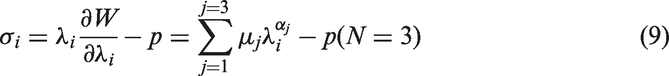
By virtue of the upper incompressibility constraint, equation (9) can be rewritten by eliminating P

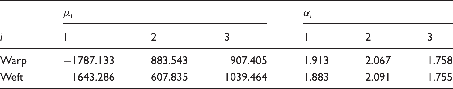
Coefficients of the stress-strain fitting curves.

Coefficients of the constitutive relation in both directions.
From the above simulation, the constitutive relationship of the woven fabric under uniaxial tension had been accurately evaluated. The typical comparison charts between measured data and fitting curves in both directions are plotted in Figure 5.
Comparison between experimental data and the stress–strain model. (a) Stress–stress curves in warp direction; (b) stress–stress curves in weft direction.
As can be seen from Figure 5, the Ogden model produces more precise rigid of such woven fabric at higher strain region than that of the lower strain region (less than 1%). The difference is due to the assumption of isotropy and elasticity on textile during calculation. But the interaction of warp and weft yarns will actually lead to complex anisotropy. In a practical engineering, however, excessive air inflation may lead to large deformation for an airship during installation procedure. In very severe cases, the airship capsule could burst during rising process and lead to mission failure. Consequently, stages with large stress and strain are the issues that need special attention. In other words, the accuracy of the Ogden model can satisfy the engineering application, especially at the initial stage of design process.
Cyclic-uniaxial tensile tests
It is known that when an airship capsule is working in normal operation condition, the internal–external pressure may changed due to inner (capsule filled or deflated) or outer (variations of wind load, temperature effect and atmospheric pressure gradient) reasons [1]. Therefore, the coated fabrics would be likely under cycle loading [1]. To make a clear understanding of an airship envelop, it is significant to detect the characteristics of coated fabric materials under repeated loading.
Specimens and test set up
Maximum and minimum tensions of cyclic uniaxial tensile tests.
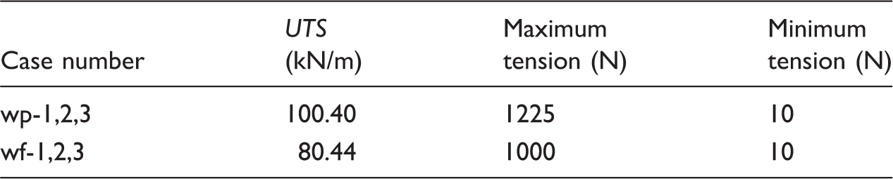
According to the regulation of FAA [22], security coefficient was defined to be 4 for the coated material of aircraft vehicle during working condition. In other words, one quarter of the UTS (measured in the former mono-uniaxial tests) were regarded as the threshold value of tension (maximum tension) and applied to the warp and weft specimens, respectively. Considering the stress of a semi-rigid or rigid airship is hardly to wipe clean during working procedure, the least tension was set to be 10 N. Such measure can also avoid wrinkle emerging during loading which may lead to the experimental failure, see Table 4.
Results and discussions
Mechanical properties under cyclic-uniaxial tension
The measured stress–strain scatters of each yarn direction are shown in Figure 6 correspondingly. To make an intuitive comparison with each other, the stress–strain curves of three specimens in the same direction were plotted together in a coordinate system. However, the coordinate origin of the test curves, relevant to three samples for each direction, was separated and shifted with an interval of 0.5% along the strain axis.
Stress–strain curves of cyclic-uniaxial tensile tests. (a) Three specimens in warp direction; (b) three specimens in weft direction.
As can be seen from Figure 6, there are obvious residual strain in the stress–strain curves. That was due to the threshold value we set during cycling-tensile tests. To make a clear illustration of such nonlinearity, it would be well if we pick out the threshold tension of cycling-uniaxial specimens from Figure 4. Apparently, a non-elastic property emerged on both the warp and the weft specimens, see Figure 4. Therefore, obvious residual strains appeared during cycle loading. Moreover, Figure 6 shows an excellent experimental reproducibility in the three specimens both in warp (Figure 6(a)) and weft (Figure 6(b)) directions. The effect of the cyclic loading is visible mainly on the first unload–reload cycle. For the range of the cyclic loadings, the plastic strain decreased with the cyclic numbers. Such strongly nonlinear property presented at first cycle indicates the constitutive yarns of the woven structure have an insufficient adjustment. Then with the increasing number of cycling, increments of strain value turned out to be less and tended to be stable approximately. Besides, the hysteretic curve presented a specific sunken property in each loop and the slope of each cycling load was gradually magnified. Such phenomenon indicates the stiffness of such woven fabric was enhancing with the increasing loops. What is more, the area of each hysteretic loop turned to be approximately identical and the gradients of unload and reload for the latter hysteretic curves tended to be parallel. Meanwhile, with the residual strain increment decreasing, the stress–strain curves translated similarly to be oblique lines, i.e. the linear mechanical response of such membrane came to be slightly obvious in the latter cyclic loadings.
Increment of the residual strain
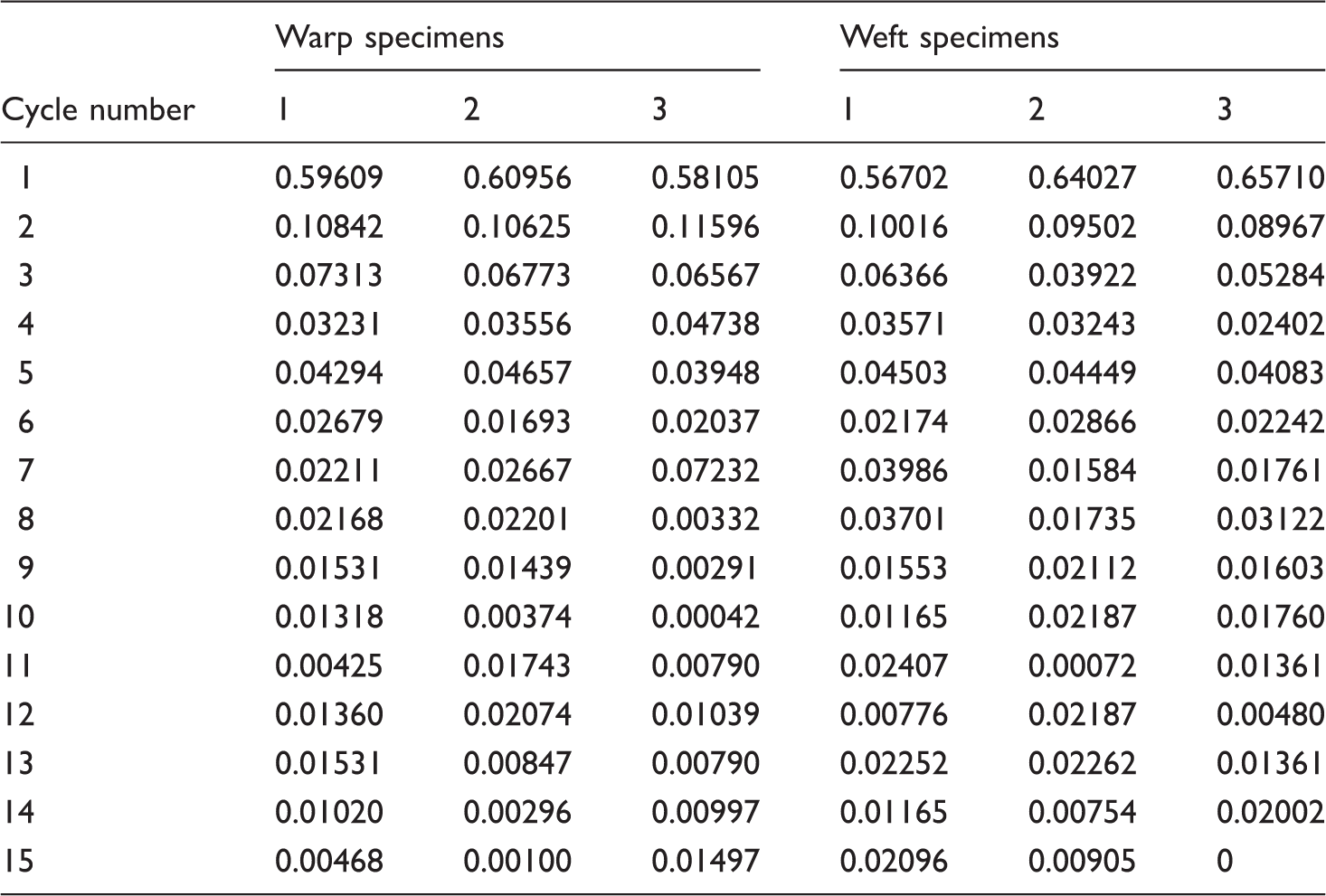
According to the above analysis, mechanical performances of such membrane material would translate to be steady with the stability of the residual strain increment. In order to isolate the effect of the cyclic numbers on the residual strain increment, the residual strain increment was firstly described as

The residual strain increment of each sample.

Coefficients of fitting curves.

The optimal matched curves between the loop number and the calculated residual strain increments of measured data are depicted in Figure 7. The first cycle, apparently, had a considerable residual strain increment in both directions, which is 57.6% and 30.4% for the warp and weft directions, respectively. Besides, the residual strain increment decreased rapidly and came to be zero in the latter loops, i.e., the residual strain tended to be constant. In other words, the mechanical properties of such new coated fabric approached to be stable after several cycles.
Fitting curves of the cycle number-residual strains increment. (a) Fitting curve of the warp direction; (b) fitting curve of the weft direction.
Elastic modulus
The mechanical properties of the woven fabrics will be stable after the 8th cycling according to equation (14). Therefore, the elastic modulus of each yarn direction can be fitted separately with the experimental data from a stable loop, i.e., a hysteretic curve after the 8th cycling. It was feasible to apply the upward slope of the 12th cycling to calculate the corresponding values.
Coefficients of fitting curves.

Figure 8 is plotted to show a vivid comparison between the fitting curves and the rising part data of the 12th cycling.
Comparisons between the fitting curves and measured data. (a) The warp specimens and relevant fitting curves; (b) the weft specimens and relevant fitting curves.

Elastic modulus of warp and weft direction.
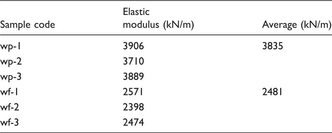
By comparing the elastic modulus of the Uretek3216A fabric [23], which is 1317 kN/m and 1149 kN/m to the warp and weft directions correspondingly, it is obvious that the new membrane fabric possesses high stiffness. Such mechanical property is vital to an eligible airship envelop material. What is more, the elastic modulus in the warp direction is higher than that of the weft direction due to special knitting craft. Ambroziak et al. [15] stated that the uniaxial tensile tests results can be safely utilized to estimate the behavior of coated fabrics for preliminary design. Therefore, as for the similar membrane materials, the upper progress is suggested to roughly estimate the elastic moduli during the initial design stage or if biaxial test conditions are limited.
Performance of welding seams
In general, an airship capsule is fabricated by multiple membrane material parts because of its huge body and considerable area. Therefore, it is necessary to investigate the welding performance for any particular textile product. In general, appearances of welded seams are determined primarily by the type of welding and processing method offered [24]. The overlapping weld, consists mostly of parent material, welding strip and adhesive, is commonly adopted in the practical airship capsule welding due to its practicability and reliability. But permanent damage may generate on the membrane material because of high temperature during seaming. Besides, the dimension of welding strip is vital to the success of controlling the whole weight of an airship. Since too short welding width may lead to welding failure whilst overlong can result in extravagant. Therefore, the seam experiments were performed carefully to evaluate the welding performance on the new woven fabrics.
Specimens and test set up
Dimensions of the welding test samples are depicted in Figure 9. Tests have also been carried out on Zwick/Roll Z100, loaded up to failure with the constant stretching rate of 20 mm/min. The same raw material was employed as welding strip. High-frequency welded was applied. The homogeneity and penetration for seam line should be guaranteed while welding. Four kinds of welding samples, with 40 mm, 60 mm, 80 mm and 100 mm welding width, respectively, were fabricated. Each group consisted of ten specimens including five warp samples and five weft ones.
Geometry of welding test specimen (mm).
Results and discussions
Welding failure mode
Failure modes of welding specimens.
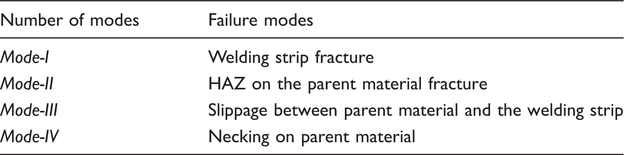
Among the upper deduced four failure modes, the first three damage categories emerge on the welding regions, as can be seen from Figure 10. The fourth failure form, however, is parent material damage unquestionably, shown in Figure 11.
Typical ruptures of welding specimens with 40 mm welding width. (a) the Mode-I and Mode-II failures; (b) the Mode-II failure; (c) the Mode-III failure. Typical ruptures of welding specimens with 60 mm, 80 mm and 100 mm welding width. (a) typical transverse failure; (b) typical oblique string fracture; (c) typical necking fracture.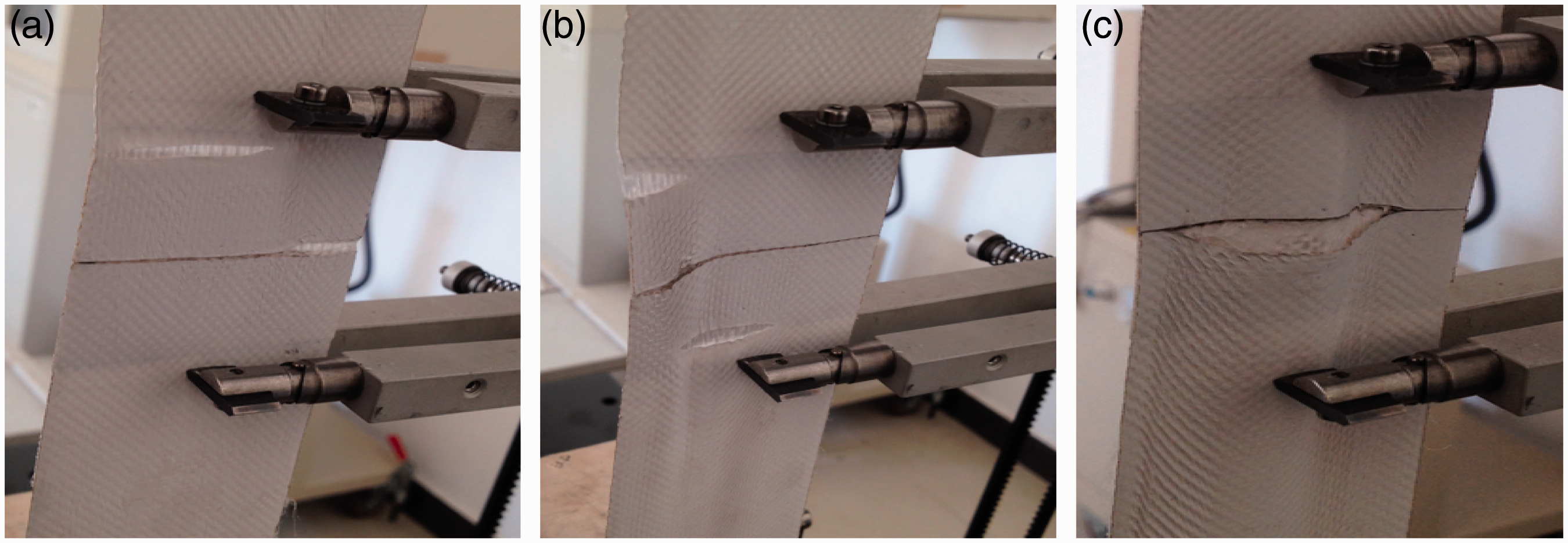

Figure 10(a)–(c) shows the failure modes of welding specimens with 40 mm welding width. Among which, Figure 10(a) combines the Mode-I and Mode-II failures. In this regard, the parent material yarns on heat affected zone (HAZ) [24] turned out to be sparse and the welding strip on the same region became scattered simultaneously in the mid and later stage. Then, apparent crack gradually presents with the ascending load. Figure 10(b) shows the Mode-II fracture. Rupture generated on the HAZ with evident tear damage on the parent material in the final state. As illustrated by Figure 10(c), two pieces of welding strips separated from each other first, then the drawback expanded in separated regions with the increasing load. However, no obvious damage emerged on the welding strip during the aforementioned period. Such failure is due to invalid adhesive between the parent material and the welding strip.
All of the graphs in Figure 11 testify to the fact that the damage form of welding specimens with 60 mm, 80 mm and 100 mm seam width is the Mode-IV, i.e., the welding specimens present similar damage to that of mono-uniaxial tensile tests. Such phenomenon manifests that samples with 60 mm–100 mm welding width are qualified.
Comparisons between the intact and welding textiles
The relevant stress–strain curves of specimens are plotted in Figure 12. Experimental data were processed identically to the mono-uniaxial tests.
Stress–strain curves of specimens with 40 mm–100 mm welding width. (a) and (b) are the welding specimens with 40 mm welding width in warp and weft direction; (c) and (d) are the welding specimens with 60 mm welding width in warp and weft direction; (e) and (f) are the welding specimens with 80 mm welding width in warp and weft direction; (g) and (h) are the welding specimens with 100 mm welding width in warp and weft directions.
Theoretically, chemical reactions may emerge inevitably on the ultra high molecular weight polyethylene fiber during high temperature. Consequently, the order of precedence on warp and weft yarns can be destroyed in HAZ and leaded to the fibers harden and tendering. Such phenomenon can lead to more complex mechanical properties on such woven fabrics. However, the foremost aim in this paper is to study the macroscopic rules of the airship envelop fibers subjected to high temperature and detect the optimal welding width which can be utilized in airship design directly rather than researching microanalysis on the molecular formula transformation. Hence, the analysis of stress–strain curves was made thoroughly below.
Figure 12 reveals hyper-elastic characteristics on the stress–strain curves of welding specimens excepting the specimens with 40 mm welding width. It was obvious that the stiffness of 40 mm welding specimens sharply declined especially at the third stage (see Figure 12(a) and (b)). That was because 40 mm welding width was incapable of sufficiently exerting the fabric’s mechanical properties. As for the specimens with 60 mm–100 mm welding width, significant differences were easily found when compared to intact specimens in Figure 4. Specifically, unlike the intact specimens, there was almost no the first loading stage for the welding specimens, i.e., there were approximately 0.1% and 1% strain occurred on the welding specimens and the intact specimens, respectively. Such phenomenon also emerged on the 40 mm welding width samples. What is more, a total of around 2% breaking elongation had been detected on specimens with 60 mm–100 mm welding. Such value was only nearly half than that of the intact specimens. All these appearances testified the fact that the stiffness of the textile had been transformed to be more rigid after welding. Therefore, it is of great importance to consider the co-deformation in the adjacent welding zones while charging and discharging process.
UTS of warp specimens (kN/m).
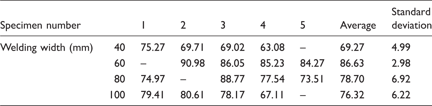
UTS of weft specimens (kN/m).

According to Tables 10 and 11, the standard deviation of the measured data was drastically higher than those of the intact specimens which were only 1.64 and 1.70 in the warp and weft directions correspondingly. What is more, one can discover an obvious higher dispersion in samples with longer seam width, especially for the weft specimens with 10 mm welding width. In general, dimension of 60 mm welding width was relatively stable.
As for the UTS of welding specimens, it is no doubt that the UTS of specimens with 40 mm welding width owned the lowest average values. However, an interesting phenomenon occurred in the specimens with 60 mm–100 mm welding width. It is generally believed that a welding specimen should perform at least parallel strength with parent material, otherwise mechanical behaviors of the raw material may decrease and welded components should be limited by the weakest section during product design [24]. However, as can be seen from Tables 10 and 11, the UTS of the welding samples were generally lower than that of the intact strip specimens. To acquire a better comparison between the welding samples and the raw material specimens, Figure 13 was plotted. The welding width of the intact specimens was set to be 0 mm.
Comparisons of UTS between the welding and intact specimens. (a) UTS of specimens in warp direction; (b) UTS of specimens in weft direction.
The analysis of Figure 13 shows that unlike the welding mental materials, the UTS of textile products with seam will decrease within certain limits. As for the GQ-6 material, UTS of specimens with 40 mm welding width amounts to approximately 32% and 27% lower than that of the intact samples in the warp and weft directions relevantly. As for the larger welding width, though the failure occurred on the parent material (excepting the invalid samples), the UTS of such samples also showed a decline. Meanwhile, the average values revealed no consistency. The utmost factor is the mechanical characteristics of the woven material had changed due to high temperature. The longer welding width will be subjected more by HAZ and transform to be more complex material. It should be noticed that the manufacture errors on specimens could not be neglected. Therefore, specimens with 60 mm welding with revealed the largest UTS rather than the ones owned 100 mm welding width.
Optimal welding width
In general, the capsule of an airship is consisted by lamellar membrane material. Meanwhile, the longitude direction of an approximate elliptical airship capsule is set to be parallel to the warp direction, see Figure 14. That is to say that the welding commonly occurred at the weft direction. Additionally, the weight of an airship is strictly limited to ease the burden of energy system. It is a costly and not necessarily process to detect the complicated mechanical behaviors of the woven material in HAZ for a practical engineering project during preliminary design. Therefore, a discount on the UTS of intact membrane for the welding ones is undoubtedly a straightforward method. An optimal welding width should be considered undoubtedly. According to the section Comparisons between the intact and welding textiles, we can conclude that the 60 mm welding width was an optimal dimension after balancing the UTS and the standard deviation. The average UTS of the welding material are approximately 13.77% and 10.91% lower than those of the intact fabrics in the warp and weft directions, respectively. Considering the security of airship during working condition, around 15% discount was offered for the new coated fabrics rather than directly applied the discount of 10.91%.
External view of an airship welded joint direction.
Conclusion
In the present work, the high ultimate tensile stresses of the new coated fabrics in each yarn direction have been successfully identified by the mono-uniaxial tensile tests. It is observed that GQ-6 presents an approximate rupture stretch ratio in each yarn direction which reveals a superior interaction with inner yarns. The stress–strain characteristics are obtained by the Ogden model and a cubic poly-nominal model on the basis of the mono-uniaxial and the cycling-uniaxial tensile experiments, respectively. High correlation coefficients are obtained through comparing the given novel formulas with the actual measured data. Additionally, the secant modulus of the aforementioned cubic polynomial is defined as the elastic modulus of such new material. The welding properties are also investigated in this study. The most important finding is the ultimate tensile stresses of the welding samples decrease within certain limits due to inevitable existence of the heat affected zone. Therefore, an appropriate welding longitude is of important to a specific coated fabric. The economic welding width for GQ-6 is found to be 60 mm.
The above conclusions can be directly employed in FEM simulation or the preliminary design in practical engineering. In the future work, the shear properties and tear resistance under uniaxial and biaxial loading, the permeability and the fatigue property under extremely poor working conditions, etc. can be elaborately performed and analyzed.
Footnotes
Declaration of conflicting interests
The author(s) declared no potential conflicts of interest with respect to the research, authorship, and/or publication of this article.
Funding
The author(s) disclosed receipt of the following financial support for the research, authorship, and/or publication of this article: The authors would like to acknowledge the 46th Research Institute, 6th Academy of China Aerospace Science & Industry Corp. for the GQ-6 materials support of the research work.