
Abstract
In the present study, coating formulations based on carbon nanoparticle (125–150 nm) and two component polyurethane resin [Polyester polyol-8 and hexamethylene diisocyanate [C8H12N2O2 (NCO-(CH2)6–NCO)] have been prepared in concentration of 5,6,7,8, 9 and 10 g of carbon black in 100 ml of polyurethane solution and was applied on cotton fabric adopting knife over roller coating technique. The coated fabrics were evaluated for surface resistivity and relevant microwave properties i.e. permittivity, scattering parameters, reflection, transmission, absorption, reflection loss and electromagnetic interference shielding in HVS free-space microwave measurement system. It is observed that increasing the carbon content increases the permittivity values and decreases the impedance. It is seen that with increase of carbon content up to 7 g, absorption increases due to increase of permittivity while with further increase of carbon content from 8 to 10 g, absorption decreases due to increase of conductivity and thereby increased reflection. The coated fabric at 6.55 wt% carbon and 93.45 wt% PU in thickness of 1.3 mm has shown about 46% absorption, 29.49% transmission and 24.5% reflectance in X (8.2–12.4 GHz) and Ku (12–18 GHz) frequency band. When electrical thickness of coated fabric equals λ/4, a peak of reflection loss is observed due to Salisbury absorption mechanism. Highest reflection loss of –31.39 dB at 17 GHz, more than 20 dB in bandwidth of 16–18 GHz and more than 10 dB in entire Ku- band is achieved. Coated fabric may be used as apparel for protecting human being from hazardous microwave and for radar absorbing structural materials for defence applications.
Introduction
Recently, the problem of radio-frequency interference or electro-magnetic wave interference (EMI) in the form of leakage of information, cross talk and generation of noise etc. has arisen due to excessive use of electronic and electrical equipments containing digital devices/circuits in the field of industry, military, consumer section and scientific applications [1]. EMI is the result of emission of unwanted electromagnetic noise/ radiated signals, which cause unacceptable degradation to system/equipment’s performance. Proliferation of electronic equipment and wireless system over the past few decades has increased the vulnerability to electromagnetic interference [2]. The sources emitting electromagnetic waves are mainly - cell phone (900–1800 MHz), radar signal (1–110 GHz), FM/AM radio broadcasting waves (30–300 MHz and 300–3000 KHz) and to some extent domestic appliances. These electromagnetic wave can damage communication system and safety operation, it can prevent the proper use of the radio frequency spectrum, ignite flammables or even may have a direct effect on human tissue which may create serious health problem viz. leukemia, brain tumours, Alzheimer’s disease, allergies, stress and sleep problems etc. [3–5]. Prevention from hazardous effect of electromagnetic wave and as a countermeasure of radio and electromagnetic interference, an electromagnetic wave reflecting/absorbing material is needed which may act as a shield against the penetration of such radiations. EMI shielding is defined as prevention of propagation of electromagnetic wave from one region to another by using conducting or magnetic materials [6,7]. EMI shielding is obtained either by reflection or by absorption mechanism. For this, shield should have mobile charge carrier or electric /magnetic dipoles which interact with the electromagnetic fields in the radiation [8].
Researchers have worked on development of electromagnetic wave protective fabric by applying coating formulations on textile substrate based on magnetic/ conducting ingredient i.e. ferrite materials, activated carbon fibre polymer composites, coating based on CNT formulation, use of graphene in polymer composite form etc. [9–16]. These are heavier in weight, made on multilayer principle and for narrow frequency band only. Light multilayered dielectric materials with good quality absorber are also available, but it consists of several layer PU foam or similar materials that are bulky and cannot be used due to outgassing behaviour [17].
Carbon black, a form of paracrystalline carbon with high surface area-to-volume ratio, made by the controlled combustion of acetylene, is highly conductive and is employed in radar absorbent materials for wide spectral band. Uniform dispersion of carbon black in ethylene butylacrylate copolymer matrix offered microwave dielectric properties in 0.1–3 GHz frequency range [18]. Lopes et al. [19] investigated for non-woven polyacrylonitrile fabric impregnated with conductive carbon black in concentration of 20, 33 and 50 wt% for microwave absorption properties in X-band. Fabric containing 33 wt% of carbon black showed highest absorption (–22 dBm). Kumar [17] developed acetylene black rubber for broadband absorber of electromagnetic energy and lighter than ferrite-loaded absorber. With 40 wt% carbon black in rubber offered reflection coefficient of about –15 dB at 9.5 GHz in 3-cm thick sheet. Composite containing 7 wt% carbon black and 3 wt% gas phase grown carbon fibre in polyethylene offered reflection loss of –37 dB at 9.5 GHz at 1.98 mm thickness [20]. Al-Saleh and Sundararaj [13] prepared a composite using 7.5 vol% carbon black in polypropylene matrix which offered EMI shielding effectiveness (SE) of 18 dB in 1-mm thick composite materials in X- band. Yang et al. [21] prepared epoxy composite material with core-shell structure of polyaniline/ carbon black containing 10–30 wt% of nanoscale carbon black, sample with 30 wt% carbon black has shown maximum reflection loss of –40 dB at 11.4 GHz and more than –10 dB in range of 10–13.1 GHz in 2 mm thickness. Work reported so far on electromagnetic wave protective fabric is on multilayer system in higher weight range that is applicable for industrial purpose only.
Several researchers worked on electromagnetic wave absorbing material using carbon black as a main conducting ingredient, they reported adequate level of permittivity achieved. Chung et al. [22] prepared carbon black-polyvinyl chloride composite up to 0.8 volume fraction of carbon black. Dielectric constant increases up to 0.3 volume fractions, beyond this due to percolation threshold, permittivity decreases to zero. Escarmant et al. [23] prepared structural composite materials in three layers of dielectric materials; outer layer permittivity of 3, intermediate layer permittivity of around 5 and inner layer permittivity ranges from 15 to 20. An attenuation of 10 dB at 6.75 mm thickness was reported. Zhou et al. [24] studied permittivity of carbon black in polyimide honeycomb composite structure, permittivity of 3.8 to 2.7 in 8–12 GHz was observed in thickness of 0.66 mm. Roussel et al. [25] observed a permittivity of 10.4 at 100 Hz and 8.9 at 10 kHz in nanocomposite of carbon black in polyurethane. Bhattacharya et al. [26] also studied nanocomposite of MWCNT in polyurethane matrix and observed a peak of reflection loss of –36.44 dB at 12.05 GHz and –42.53 dB at 10.98 GHz with real permittivity 15–16 and imaginary permittivity 2.5–3.5. Kumar [17] observed permittivity of 8 (real) and 3.5 (imaginary) at 9.5 GHz in acetylene black rubber with 40 wt% carbon black. Zou et al. [27] prepared microwave absorbing composite using activated carbon fibre (ACF) in epoxy and polyamide resin in concentration of 0.21–1.73 wt% in thickness of 4 mm. At 0.43 wt%, highest reflection loss of –26 dB at 8.0 GHz was reported with real permittivity (ɛ’) 11-6 and imaginary (ɛ”) 5-3 in 2–18 GHz. Folgueras et al. [28] studied the effect of carbon fibre fabric impregnated with polyamide conducting polymer and obtained absorption of 87% in 8–12 GHz in the composite material. Thus, it is found that carbon black emerged as an eminent ingredient suitable for any binder/ resin attributing permittivity and which consequently renders loss to the electromagnetic wave.
The present work is focused on preparation of lightweight, thin, flexible microwave absorbing fabric for broad frequency range. Cotton fabric is coated with coating formulation containing carbon black nanoparticles in polyurethane matrix in different concentration and was studied for microwave properties in 8–18 GHz. The coated fabric (sample CNC_3) at 6.51 wt% carbon black and 93.49 wt% polyurethane in thickness of 1.3 mm has shown about 46% absorption, 29.49% transmission and 24.5% reflection in X (8.2–12.4 GHz) and Ku (12–18 GHz) frequency band. Reflection loss of –31.39 dB at 17 GHz, more than –20 dB in 16–18 GHz and more than –10 dB in entire Ku-band is achieved. EMI shielding of ∼ –18 dB in entire X and Ku-band is also obtained. Owing to lightweight, thin (<1.3 mm) and flexible, coated fabric may be used for apparel purpose for protecting human being from hazardous microwave and also for radar absorbing structural (RAS) materials for defence applications reducing the radar cross-section of military strategic objects/ vehicles.
Materials and methods
Materials
Carbon black coated samples are prepared on plain weave cotton matt fabric 220.0 gsm with warp and weft 44 and 33 per inch. Thickness of basic fabric is 0.86 mm (measured in Wallace Thickness Tester under 200 g/cm2). Polyester polyol-8 (density ∼1.0 g/cc, Ciba Geigy Corpo) and hexamethylene diisocyanate [C8H12N2O2 (NCO-(CH2)6–NCO)] (purity 99.99%, molecular weight 168.20 g/mole, density ∼1.05 g/cc, Merck) are used as received. Carbon black, particle size 125–150 nm, 50% compressed grade, bulk density 50–90 gm/litre and electrical resistivity 0.25 ohm.cm, acetone absorption value –27 ml/5g (min), (Sun petrochemical, Mumbai) has been used as received. Using coating formulations of carbon nanocomposite (CNC) in polyurethane with carbon black 5, 6, 7, 8, 9 and 10 g, respectively, in 100.0 ml of polyurethane solution (polyol and hexamethylene diisocyanate 50 ml each), six samples (size ∼15 cm × 15 cm) marked as CNC_1, CNC_2, CNC_3, CNC_4, CNC_5 and CNC_6 are prepared. Beyond 10 g of carbon black, coating solution becomes too thick to coat on fabric. Carbon black was first wetted and dispersed in methyl ethyl ketone (MEK) and then added to PU solution under constant magnetic stirring for 30.0 min (600 r/min, at 30℃) followed by sonication for 2 h (40 KHz, 40℃) in a manner that carbon particles may uniformly disperse in PU solution, making a homogeneous coating paste. Viscosity of coating paste was 3.28 Pa.s at a shear rate of 10.5 s−1 (measured in Modular Compact Viscometer, Physica, 301, Anton Paar, Dynamic Measurement system). Coating was carried out on both sides of fabric in Mathis Lab Coater, a mechanized knife-over roller coating head (UK origin Lab Model coating head) (Figure 1). The coating parameters were; knife speed ∼30 cm/ min, curing time 30 min at temperature of 120℃ with 1500 r/min fan speed.
Mathis Lab coater, knife over roller coating system.
Characterization
The coated fabrics were evaluated for add-on, carbon content and thickness by high-precision electronic balance and Wallace thickness gauge tester (at 200 g/cm2 pressure). The morphological structures of coated samples were examined under scanning electron microscopy [Model no. EVO 50, CARL ZEISS, UK, Low Vacuum SEM]. The SEM image is formed by the back scattered and secondary electron. The thermal stability of carbon black was studied in Thermal Gravimetric Analysis Instrument (Model No.TGA2950, TA Instrument, USA) at a heating rate of 10℃/min in air/N2. It is stable up to 600℃. Surface resistivity was measured as per ASTM D257 standard using Resistivity Probe Model no. 8038B. Microwave properties were evaluated by HVS free-space microwave measurement system (HVS Technologies, Pennsylvania, USA). It comprises a pair of spot-focusing horn lens antennas (transmit and receive antennas), Vector Network Analyzer (Agilent, E8362B) and a personal computer for data acquisition (Figure 2). The spot-focusing horn lens antenna consists of two equal plano-convex dielectric lenses mounted back-to-back in a conical horn antenna. By using adapter for different bands, the spot focusing antenna can be used from 10 MHz–50 GHz. In this method, S11 and S21 parameters of a planar coated fabric samples were measured for a normal incident plane wave in frequency of 8.2–12.4 GHz (X- band) and 12–18 GHz (Ku-band) separately.
HVS free space microwave measurement system.
Results and discussion
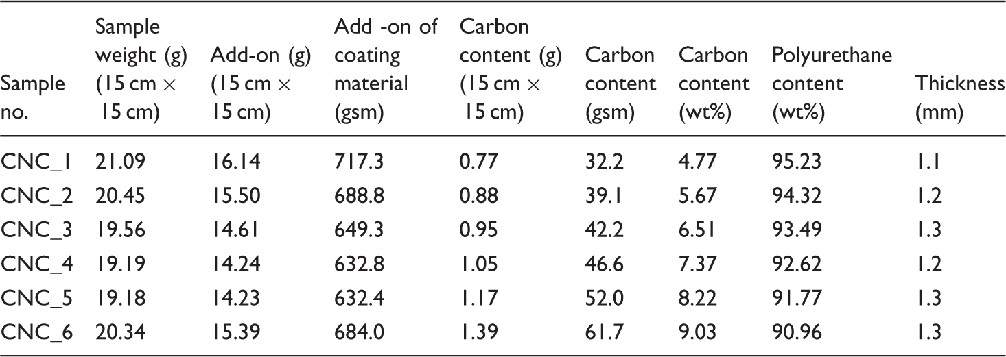
Add-on and thickness
Add-on and thickness of coated fabrics.
SEM image of carbon particle and coated fabrics
SEM studies of carbon particles and morphological studies of coated fabrics have been carried out. The SEM of carbon black particles has been carried out at magnification of ×15,000 and ×20,000. The smallest size seen is 144.5 nm at ×15,000 (Figure 3a) and 127.7 nm at ×20,000 (Figure 3b). This shows that particle size lies in range of 125–150 nm. The SEM micrographs of coated fabrics (Figure 3c to h) describe uniform distribution of carbon filler particles and it is evident from cluster of dots in the micrograph that as the concentration of carbon black increases from 5 to 10 g (CNC_1 to CNC_6), the density of these dots is also increased. The uniform dispersion of these fillers has provided uniform microwave properties in the coated samples.
SEM microgram (a, b) for carbon black at magnification ×15000 and ×20000 and for coated fabrics (c) CNC_1 (5 g), (d) CNC_2 (6 g), (e) CNC_3 (7 g), (f) CNC_4 (8 g), (g) CNC_5 (9 g) and (h) CNC_6 (10 g) at magnification ×5000.
Surface resistivity
Surface resistivity is defined as ratio of potential drop per unit length to current flowing per unit width on surface of coated fabric. Conversely, it is a measure of surface conductivity of fabric, less resistive more conductive. Surface resistivity, the resistance of unit square thin sheet, is one of the important characteristic of the materials deciding whether the electromagnetic wave will transmit through or reflect from interface of medium. It is seen that surface resistivity decreases exponentially from sample CNC_1 (30.0 × 10³ Ω/□) to CNC_6 (0.149 × 10³ Ω/□) with increase of carbon content from 5 to 10 g (Figure 4). Grey fabric is almost insulating, its surface resistivity is very high (850.0 × 10⁶ Ω/□). For samples CNC_1 and CNC_2, with increase of carbon content from 5 to 6 g, surface resistivity decreases moderately from 30000 to 29000 Ω/□, when carbon content is increased up to 7 g (CNC_3), the resistivity drops exponentially to 8600 Ω/□. When carbon content is further increased from 8 to 10 g, resistivity drops drastically to a very low value of 149.0 Ω/□.
Surface resistivity of coated fabrics.
Microwave properties
Permittivity
Permittivity (ɛ) is defined as material’s ability to pass the external electric flux / electric field through it and store the electrical potential energy. Polar materials have higher permittivity than the non-polar. Wave while propagating in the material, gets dissipated due to presence of electric and/or magnetic dipoles and its energy is converted into heat. Permeability is the measure of the ability of a material to support the formation of a magnetic field within itself. Magnetic permeability depends on magnetic susceptibility, µ = µ0 (1 + χm), for non-magnetic materials, magnetic susceptibility (χm) is considered zero and µ = µ0 (permeability of free space, 4π × 10−7 H/m), (relative permeability, µr = µ/µ0 = 1) [29,30]. For non-magnetic materials, interaction of a material with electromagnetic field is due to complex permittivity (ɛ*). It consists of a real part (ɛ’) associated with the energy storing capacity of the material and an imaginary part (ɛ”) related to the electrically dissipative nature of the materials [2]. Therefore, permittivity is represented by a complex function of angular frequency as ɛ (ω) = ɛ’ (ω) + j ɛ” (ω) [31].
In the present work, permittivity of coated fabric is depicted graphically in Figure 5. From Figure, it is seen that with increase of carbon content from 4.77 to 9.03 wt%, the permittivity increases from sample CNC_1 (Real (ɛ’): 7.730–6.244; Imaz (ɛ”): 3.553–1.654) to sample CNC_6 (Real (ɛ’): 16.731–14.197; Imaz (ɛ”): 12.455–9.924) in entire X and Ku-band.
Graphical illustration of permittivity (a) real and (b) imaginary in X and Ku- band.
Impedance of coated fabric
Impedance of coated fabrics.

Scattering parameters
Microwave properties of materials are basically measured from the scattering parameters; these are mainly expressed as S11 and S21 parameters. S11 parameter is the measure of reflecting behaviour of surface, whereas S21 parameter depicts the transmission behaviour of microwave through the material. S-Parameters were measured by HVS free-space microwave measurement system (Figure 2). The higher S11 value indicates higher reflection and similarly, the lower S21 value corresponds to low transmission and more EMI shielding. S11 and S21 values are graphically illustrated in Figure 6(a and b). It is seen that the increases of carbon content, S11 parameter increases from sample CNC_1 (–9.472 to –7.926) to CNC_6 (–3.263 to –2.575) whereas, the S21 parameter decreases from sample CNC_1 (–2.452 to –3.597) to CNC_6 (–7.180 to –8.067) in frequency 8.2–18.0 GHz. Also, in Ku-band, the S11 values are higher than that in X-band indicating more reflection in Ku-band than in X-band. On the other hand, the S21 parameters are lower in Ku-band than in X-band, indicating more shielding in Ku- band than in the X- band.
Graphical illustration for scattering parameters (a) S11 parameters, (b) S21 parameters and (c) reflection, (d) transmission, (e) absorption.
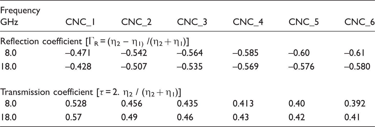
Reflection, absorption and transmission
Electromagnetic wave is represented by the partial differential equations


Reflection and transmission coefficient of coated fabric.
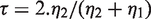
Transmission is calculated with S21 parameters using relation

Absorption is worked out as % Absorption = 100 – (% Reflection + % Transmission). Initially, with increase of carbon content up to 7 g, the absorption increases from CNC_1 (31.848–40.196%) to CNC_3 (45.938–46.006%) due to increase of permittivity, on further increase of carbon content up to 10 g, absorption decreases from sample CNC_4 (37.816–32.491%) to CNC_6 (33.683–29.122%) due to increased reflecting behaviour of coated fabric (Figure 6e). Similar observations are also reported by Lopes et al. [19] and Zou et al. [27].
Attenuation and reflection loss
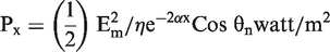
Reflection loss is measured by the power of reflected wave from the coated fabric backed by a mettalic conducting plate. It comprises losses incurred due to absorption, multiple reflections between fabric and metallic surface, destructive interference between reflected wave from front and rear surface of fabric. Material with high absorption will offer higher reflection loss. The average power flowing through unit area for lossless dielectric medium is given by Poynting wave equation and is interpreted as an instantaneous power density [29].

For lossy dielectric medium, Ey and Hz are not in time phase and power propagation equation reduce to

The attenuation constant for each sample have been worked out at frequencies 12.4 GHz and 18 GHz using equation (12) and is demonstrated in Figure 7. Attenuation constant increases exponentially from CNC_1 to CNC_6. Sample CNC_6 shows maximum attenuation. Accordingly, its transmission is least (19.142–15.606%) in X and Ku-band.
Graphical illustration of attenuation constant of coated fabrics.
Measurement of reflection loss
Theoretically, reflection loss curves can be plotted at a matching thickness and frequency according to the equation
Reflection loss of coated fabrics.

Salisbury screen absorber mechanism.
The most common and simple structure to reduce the level of the reflected power from a metallic surface is the single layer structure known as Salisbury screen, which is a sheet of porous material (plastic foam/ honeycomb spacer) impregnated with graphite and spaced a quarter-wavelength of a metallic backing plate (Figure 8). While measuring the reflection loss, cumulative multiple reflections (reflections from front surface, from back surface of the fabric, from metal surface etc.) are taken into account when fabric sample is backed with metallic plate. For this, reflected power is expressed as R = 20 Log10 (Pr/Pi), where Pr = reflected power and Pi = incident power. Reflection loss is also expressed as RL = –20 log10 | Γ |, where Γ is the reflection coefficient (=(Z–1)/ (Z + 1)) [26,27]. It is also expressed as R =−e−jkx. Cos (2πx/λ)); R is minimum when x = λ/4 + n.λ/2 i.e. sample thickness may correspond to the quarter of wavelength [33].
Salisbury screen mechanism for microwave absorption.
When thickness of sample (x) corresponds to λ/4 of wave in the medium, due to λ/2 path difference between incident and reflected wave, destructive interference takes place and a peak of maximum reflection loss is produced in reflection loss curve (Figure 9). Sample CNC_3, thickness 1.3 mm, peak loss at 17 GHz. Sample CNC_4, thickness 1.2 mm, peak loss at 16.5 GHz. Sample CNC_5, thickness 1.3 mm, peak loss at 14.5 GHz.
For ideal microwave absorber, Zin = Zo is the primary condition. When intrinsic impedance is greater than unity i.e. |µr| > |ɛr,| maximum attenuation is achieved at thickness of λ/2 and if |µr| < |ɛr |, maximum attenuation is achieved at thickness of λ/4 [16]. In our case, condition of |µr| < |ɛr | is applied. It is seen that reflection loss increases from CNC_1 to CNC_3 due to increase of absorption and decreases from CNC_4 to CNC_6 due to decrease of absorption. Sample CNC_3 has shown highest reflection loss as this sample has maximum absorption. When carbon concentration is more than 7 g, surface becomes more conductive thereby reflection increases and absorption decreases (Figure 6c and e), this trend has also been observed in reflection loss curve (Figure 9). The reflection loss curve can better be explained on the principle of Salisbury absorber screen mechanism (Figure 8). Sample CNC_3 has shown a peak loss of –31.393 dB at 17 GHz. At this frequency, λ/4 = 4.41 mm and permittivity is 11.561, refractive index [√(ɛµ) = √ (11.561 × 1] is 3.50, λ/4 in the medium equals to (4.41/3.50) 1.29 mm. The thickness of sample CNC_3 is 1.3 mm which is very close to 1.29 mm (λ/4), giving a peak loss at this frequency due to Salisbury absorption mechanism. This sample has shown reflection loss more than –15 dB in band width of 2.5 GHz (15.5–18.0). Similarly, for sample CNC_4, maximum reflection losses of –24.776 dB has occurred at frequencies 16.5 GHz due to matching of thickness with λ/4 at this frequencies. Sample CNC_5 has offered peak reflection loss of –29.094 dB at 14.5 GHz and reflection loss more than –15 dB in broad frequency band of 4 GHz (12.5–16.5 GHz). For sample CNC_6, no reflection peak is observed as the surface became more reflective due to its highly conducting nature, transmission is less (19.142–15.606%), which rendered less reflection loss (below –10 dB) in entire X and Ku-band.
EMI SE of coated fabric
Shielding is defined as the ratio of the electromagnetic field intensity measured before and after the shielding material is installed. The shielding efficiency/effectiveness term explains the level of prevention [34]. Shielding efficiency describes the performance of the shield and is defined by the following equation

Total SE is the attenuation of propagating wave as a result of reflection, absorption and multiple internal reflections at the existing interfaces.


Following relations have been used for calculation of reflectance (R), transmittance (T) and absorbance (A) from S11 and S21 parameters [35,36]
EMI shielding effectiveness of carbon-coated fabric.


Sample CNC_6 has offered maximum SE of ∼ –18 dB (98.415%) in entire frequency range of 8–18 GHz.
Conclusion
Fabric coated with coating formulation containing carbon nanoparticles in polyurethane matrix acquires conductivity and dielectric properties and thereby it attenuates the electromagnetic wave passing through it. The trend of reflection loss of coated fabric is as per Salisbury screen absorber mechanism offering a peak of reflection loss when thickness of coated fabric equals quarter of the wavelength in that medium. Sample CNC_3 at 6.51 wt% carbon and 93.49 wt% polyurethane in thickness 1.3 mm has shown ∼46% absorption, 29.49% transmission and 24.5% reflectance in entire X and Ku (8–18 GHz) frequency band. Coated fabric has also offered EMI shielding of ∼18 dB in 8–18 GHz frequency. This coated fabric may be used as apparel/screen for protection of human being from hazardous nature of microwave and also as RAS materials for defence applications reducing the radar cross-section of military strategic objects/ vehicles and protecting from radar detection devices.
Footnotes
Acknowledgement
Authors express their gratitude to the Director, DMSRDE, Kanpur, for his kind permission and support for doing this research work.
Declaration of Conflicting Interests
The author(s) declared no potential conflicts of interest with respect to the research, authorship, and/or publication of this article.
Funding
The author(s) received no financial support for the research, authorship, and/or publication of this article.