
Abstract
Achieving whiteness and opaqueness has been an issue in paint, ceramic, paper, and coating industries from the very beginning. In the past two decades, biomimetics, for the construction of bio-inspired functional materials, has attracted much attention. As an application of biomimetic science, various structural colored materials are investigated by many researchers. The white beetle exoskeletal scales is one of those materials that shows a brilliant white color caused by randomly arranged chitin nanofibers. This material is the inspiration for achieving light weight, efficient, and low-cost white coatings by means of a nanostructure. We used this idea in this research to apply nanofibrous polymeric layer on a substrate, paper sheet in here, and witnessed the possible achievements by varying the nanofiber layer characteristics that underpin its optical properties. We coated nylon and PAN nanofiber layers on the surface of a paper using an electrospinning method and for both polymers desirably high whiteness and opaqueness achieved. Moreover, it was observed that end-use application in printing and writing is easily attained on the nanofiber-coated paper using the common methods. Measuring the properties of the nylon nanofiber-coated paper showed that the tensile strength and hydrophilicity slightly increased depending on the nanofiber layer characteristics.
Introduction
The production of white samples has been the final purpose of different industries, such as textile, paper, plastics, dentistry, and paint [1]. In these industries, the mineral particles are extensively used to achieve whiteness. Lately, the structural colors, which are based on microstructures in optical wavelength scale and are found in some of the natural beings, have attracted scientific and industrial interest. An example of a white structural color, that arose discussions in paper industry, is the Cyphochilus spp. beetle whose exoskeletal scales display a bright white in a small thickness.
In any medium, the appearance of white results from simple multi-wavelength scattering that arises from the interaction of incident light with heterogeneous dispersed matter. In simpler terms, any collection of multiply oriented interfaces between media of sufficiently different refractive index will produce the appearance of white in the absence of strongly absorbing species. For this reason, it is classed as a structural effect without the appearance of color in the absence of any selectively absorbed wavelength(s) [2]. During the past decades, it has been demonstrated that in white coatings the pores produced by the packing of pigment particles in the coating structure, not the single pigment particles alone, are the main scattering species. Indeed, micro voids are used extensively to provide the function of pigments in paints [3]. The light refraction/reflection that happens because of the refractive index change, while the light goes through a pore’s boundaries, is the reason for light scattering and leads to the opaqueness and whiteness.
Vukusic et al. [2,4] and Burresi et al. [5] showed that the Cyphochilus spp. beetle scale exhibits ultra-bright whiteness in a small thickness of 5 µm and a remarkably low mass per unit area. This characteristic is caused from the cuticular filaments that are randomly arranged. Vukusic [4] observed that the whiteness and opaqueness of these scales are higher than the synthetic coatings. The nanofibrous structures establish the largest boundary surfaces between air and polymer in the construct, which ends in a high percent of light refraction and scattering.
Burresi et al. [5] investigated the physical properties of the scale and reported that the scales appear white at any angle of observation which shows that the layer is completely random in all directions.
Hallam et al. [6] tried to mimic this natural phenomenon, in order to reach the exceptional whiteness on paper, by adding TiO2 nanoparticles to the paper coating and witnessed some improvements. There were other attempts to achieve better surface properties by means of nanostructured polymer coatings which have a particle-based structure [7]. But using nanoparticles is not a complete imitation of this phenomenon. It is evident that a nanofiber layer, instead of a film containing nanosized particles, is almost a complete imitation of the beetle white scales’ structure. Wu et al. [8] imitated the white beetle scale structure by means of applying chitin polymer in a freeze-drying process and witnessed a good opaqueness. The freeze-drying process is a time-consuming process and is not applicable easily on surfaces and for different polymers. Nowadays, by means of the electrospinning process, it is possible to put a layer composed of polymeric nanofibers on any surface.
Electrospinning is a cost effective and straightforward method of producing submicron scale nanofibers, which has attracted the researchers in the last decades [9]. Electrospinning set up is very simple, but the process is very complicated. When a sufficiently high electrified field is applied to a polymer solution, the electrostatic forces overcome the surface tension of the polymer solution and cause the ejection of a thin jet from capillary nozzle which undergoes stretching and whipping process [10].
If the nanofiber layer can be used successfully as a white coat, there would be no need for pigments, mineral particles, and even fluorescent whitening agents (FWAs). In this case, thanks to the nanofibers’ high ability in light scattering, an excellent whiteness could be reached with a thin layer on a substrate. In the present research, the practicability of this idea, inspired by nature, has been checked. In paper industries achieving whiteness in a thin layer is so important and affects the treatment costs considerably. Moreover, recently the mentioned creature has been an inspiration for approaches toward achieving a more efficient coating in paper industries. Thus paper has been chosen as the substrate for further investigations. In order to prove the correctness of the suggested idea, several samples were prepared using electrospinning of a polymer solution on a paper, and the subsequent color was measured. Afterwards, the samples were written and printed on and some of their mechanical and physical properties were measured.
Materials and methods
Materials
Nylon 66 (pellets; Molecular Weight: 262.35 g/mol; Refractive Index: n20/D 1.53) was purchased from Aldrich (Germany). Poly acrylonitrile (PAN; white powder; Mw: 150 000; Refractive Index: n20/D 1.51) was purchased from Iran Polyacryl Co. The solvents used in this work were formic acid and N, N-dimethylformamide (DMF) from Merck chemicals. These chemicals were used as received, without further purification.
Nylon was dissolved in formic acid and PAN in DMF to make solutions with 10% concentrations in respect to the mass. The solutions were magnetically stirred overnight at the room temperature in order to obtain homogeneous solutions.
Two kinds of papers were used as the substrate for the electrospinning process: a 160 g/m2 CANSON black cardboard, an 80 g/m2 Pars Paper (buff color; FWA-free paper) and an 80 g/m2 COPIMAX as an example of multifunctional white copy grade paper was used in a comparative test.
Electrospinning
In order to conduct the electrospinning, the polymer solution was placed in a medical syringe, the metal nozzle of which was flattened with tip diameter of 0.7 mm. An electrode was attached to the metal nozzle and connected to a high-voltage power supply, which can generate DC voltage up to 30 kV. A flat aluminum plate, covered with the substrate to be coated, was placed at the right angle to the nozzle and electrically grounded using an attached counter electrode to collect the fibers. The polymer solution was forced through the syringe needle, at 0.1 ml/h and 0.2 ml/h for nylon and PAN, respectively, via a syringe pump (New Era Pump Systems Inc.; NE-1800 Eight Channel Programmable Syringe Pump). The voltage controlled by the high voltage power supply was held at 14 kV in case of nylon and 20 kV in case of PVA. The distance between the nozzle and the targeted plate was 10 cm. For selecting these electrospinning conditions, a set of 72 different electrospinning experiments were conducted while changing the concentration, voltage, and distance amounts (concentration: 10, 15, and 20%; Voltage: 14, 16, 18, and 20 kV; Distance: 10, 12, and 14 cm) for each polymer. By comparing the quality of the produced layers (layer appearance in respect to being droplet-free and homogenous, and the fibers’ diameter in respect to the size and uniformity), the optimum electrospinning condition was chosen.
The electrospinning was performed at the application times of 15, 30, 60, and 90 min. As longer the time of electrospinning, the more polymer is deposited on the substrate and therefore a larger thickness of the composed layer is achieved. Since there is a direct relation between the electrospinning duration and the amount of polymer used, the samples were named by their electrospinning time.
Measurements and characterization
Electrospun fibers collected on the substrates were observed by a scanning electron microscope (SEM) (Philips XL30). The fiber diameters were measured by means of ImageJ (http://imagej.nih.gov) software.
The spectrophotometer used in the reflectance measurements was a Gretag Macbeth Color-Eye 7000 A, which employs a d/8 viewing system (diffused illumination, 8° viewing angle). With the specular component excluded, reflectance data were taken at 10-nm wavelength intervals for spectra over the range 400–700 nm. Chromaticity values (L*a*b*) were then computed from the reflectance values using a D65 illuminant and a 10° standard observer in accordance with ISO 11664/CIE S 014 standards.
Tensile strength measurements were carried out using Elima EMT-3050 in accordance with ISO 1924-2 standard guidelines (constant rate of elongation method: 20 mm/min, specimens size: 150 × 180 mm). For each sample, the mean of 10 measurements was calculated and reported.
In order to measure the surface contact angle for liquid, a digital microscope (Dino-Lite Pro) was used. The samples were placed in front of the aperture and illuminated from behind using a white LED. The images were taken right after placing the droplet on the sample surface. Furthermore, by means of the same digital microscope the samples’ cross-section images were taken and using imageJ software, the thickness of these samples was measured.
The samples were printed by two different kinds of desktop printers (hp LaserJet 1300, hp deskjet 5150) with 1200 dpi resolution. The coated samples were handled in the printer in the same manner like the usual papers.
All the reported images through this article were produced by means of a Canon flatbed scanner (CanoScan LiDe 30) with 600 dpi scanning resolution.
The Uchida whiteness formula [11] was used to calculate the samples’ whiteness since the samples produced in this research did not satisfy the CIE whiteness formula limitations and white specimens, which are out of the CIE formula boundary conditions, could not be evaluated by this formula. Uchida formula has no limit of applications, and spans a white range on the color space.
Results and discussion
Electrospinning on paper: Possibility and extension of whiteness and opaqueness achieved
At the beginning of the sample production, it was observed that as soon as the electrospinning started, the cardboard color started to fade, and as much time passed, the color changed from black toward gray and white. The reflectance curve of the substrate and the nanofiber-coated samples are shown in Figure 1. As it can be seen, as the layer thickness increases the surface reflectance increases. After 15 min, the reflectance increases by 15% and after 30 min the reflectance is about 80%, which indicates a 60% increase. After 30 min, the differences become small and the reflectance reaches a plateau value. The rate of reflectance increase along with the thickness change is shown in Figure 2.
The reflectance curves of black cardboard coated by nylon nanofiber layer with different thicknesses (spinning time). The rate of reflectance and thickness increase by increasing the electrospinning time.

As can be seen in Figure 2, there is a considerably steep rise between the samples coated at 15 and 30 min. This shows that at the beginning, the nanofibrous structure is loose and light goes through it toward the substrate/cardboard. Between the 15 and 30 min samples, the structure goes through a critical step and reaches a sufficiently high optical thickness to block out a significant part of the incident light from reaching the baseboard. When the layer acquires the necessary thickness to stop the entire incident light passing through, the reflectance reaches its maximum and becomes insensitive to any further thickness of the nanofiber layer. Comparing the change in the thickness to the change in reflectance, in Figure 2, confirms this concept.
The SEM images of the nanofiber coatings on the cardboard are shown in Figure 3. As it can be seen, the diameter variation is small and the fiber mean diameter is about 300 nm. The fiber diameter in Cyphochilus sp. beetle scale is about 250 nm [6], which is smaller than the electrospun fibers’ diameter. If the morphology of a fiber web layer coating and a film layer coating be compared, it can be understood that the number of pores in the nanofiber layer is far more than the film layer because of the geometry of the fibers. When the fibers’ diameter decreases and reaches the nano-size region, the pores size tends toward the nano region too. Since nano-scale objects have extremely high specific area, a nanofiber layer provides a high probability for each light ray to cross a surface boundary between a nanofiber and a nanopore and therefore to be reflected and refracted. Consequently, the nanofiber layer light-scattering power is extremely high. Based on the explanation given, it can be assumed that as the nanofibers’ diameter in the electrospun coating layer decreases, the light-scattering becomes greater. Therefore, finding the ways to produce thinner nanofibers will improve the light scattering efficiency.
SEM images of the 60-min nylon nanofiber coated cardboard: (a) scale = 10 µm, (b) scale = 1 µm.
It was said that the light-scattering ability is a characteristic of the nano-sized geometry, not the polymer composing the nanofibers; therefore it should be possible to use any other polymer in the nanofiber layer form, to reach a high reflectance (in the case of colorless polymers, a high reflectance creates a high whiteness) in a small thickness on a substrate. In order to examine this hypothesis, the black cardboard was coated by a layer of PAN nanofibers. The reflectance curves of PAN nanofiber-coated cardboard are given in Figure 4. It can be seen that, as for the nylon nanofiber layer, the PAN nanofiber layer covers the cardboard and gives it a high reflectance and a bright whiteness with a small amount of applied polymer, which is almost half of the polymer needed in nylon nanofiber layer. Therefore, it is confirmed that by means of colorless polymers in the nanofiber layer form, the whiteness in a small thickness on a paper substrate can be reached. This phenomenon is important because by applying different polymers, it would be possible to achieve extra properties in addition to the whiteness; based on the used polymer characteristics.
The reflectance curves of black cardboard coated by PAN nanofiber layer with different thicknesses (spinning time).
Characteristics of the black cardboard nanofiber-coated samples.

It can be seen in Table 1 that generally there is a difference between a*b* of the Nylon and PAN samples, but these differences are negligible and the difference in the paper tints is not perceived by naked eye. According to the results, the difference between the 60- and 90-min samples is small and the 60-min sample is white enough to be accepted as a white paper. Therefore, the 60-min sample was assigned as the optimum coating for the rest of the experiments.
Performance of nanofiber-coated paper in practice
Paper is a versatile material with many uses. In all of these applications, the ability of the paper to be written and printed on plays a dominant role. To evaluate the nanofiber-coated paper functionality in these applications, Nylon and PAN polymers were electrospun on a FWA-free paper and the produced paper was subsequently written and printed on.
The reflectance curve of the nylon and PAN nanofiber layer-coated papers are illustrated in Figures 5 and 6, respectively. The reflectance curve of a FWA-containing paper is given in these figures for comparison. Moreover, the SEM images of the FWA-free paper, FWA-containing paper, and nanofiber layer-coated papers are shown in Figure 7.
The reflectance curves of nylon nanofiber-coated paper in comparison with FWA-contained paper. The reflectance curves of PAN nanofiber-coated paper in comparison with FWA-coated paper. The SEM images of (a) FWA-free paper (scale = 300 µm), (b) FWA-contained paper (scale = 300 µm), and (c) nylon nanofiber-coated paper (scale = 5 µm).


Characteristics of nanofiber-coated papers.

FWA: fluorescent whitening agent.
As it can be seen in Figure 7, the FWA-containing paper, which has a higher whiteness, is composed of finer components compared with the FWA-free paper, and the nanofiber layer components are far finer. It is also evident that the number of pores in the nanofiber layer, and therefore the available surfaces for light scattering, are higher than that in an uncoated paper, such that this paper displays a higher whiteness. The nylon and PAN nanofibers’ average diameters were measured from the SEM images and were 132 and 153 nm, respectively.
The produced nanofiber-coated papers were used first to be written upon (Figure 8) and then to be printed on (Figure 9). It can be seen in these figures that writing and printing on a paper coated by a nanofiber layer is possible even with no further processing.
Writing possibility assessment on a paper before and after coating by nylon nanofiber layer. Printing possibility assessment on a paper before and after coating by nylon nanofiber layer; (a) Inkjet printing (b) LaserJet printing.
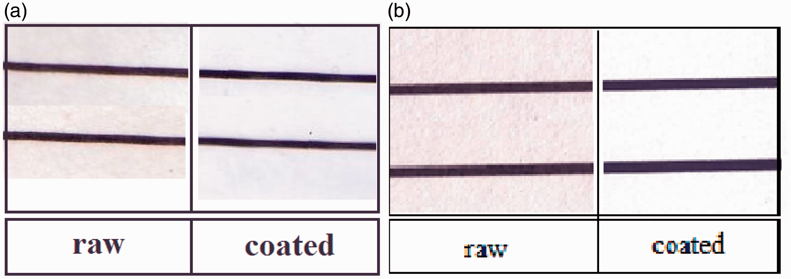
As illustrated in Figure 8, writing by means of different instruments (pencil, ballpoint pen, and marker) is easily possible. It is seen in Figure 8 that although the same pressure was used during writing on the coated and uncoated paper, the pencil trace is faded after coating the paper. Because of the really smaller size of the composing components of the nanofiber layer, it can be said that the surface roughness of a nanofiber layer is less than a paper; therefore the friction between the pencil graphite and surface is decreased in the nanofiber-coated paper which leads to the weakening of the pencil trace. Besides, the increased reflectance of the nanofiber layer can play a role in fading the pencil trace. The decrease in the surface roughness does not interfere with the pen and marker work.
It can be seen in Figure 9 that the printed line width on the coated and uncoated paper is very similar and the ink spreading on both materials is not different. It was observed that the electrophotographic printing process (by means of a LaserJet printer) gives the nanofiber layer a glossy appearance which can be attributed to the effect of hot press applied during the printing process. According to the manual of the digital printer used in this research [12], the paper surface passes over a series of rollers and at the end, the pressure and fusing rollers put the paper under a hot pressure in order to permanently fix the printed area.
For further investigation, the SEM images of the printed and written on samples are illustrated in Figure 10.
The SEM images of the printed and written on nylon nanofiber-coated paper: (a) surface of the nanofiber-coated paper (scale = 5 µm), (b) the area which has been written on using a pen (scale = 5 µm), (c) the printed area (scale = 5 µm), and (d) the boundary of the laser printed area (scale = 100 µm).
In Figure 10(b), it is seen that the ink from the pen only covered the fibers’ surface and partially filled the pores, but the printing toner composed an opaque film over the nanofiber layer (Figure 10c and d).
Generally, it can be concluded that the nanofiber layer brings up no problem in the simple printing/writing processes illustrated here. The coated paper’s high whiteness increases the writing/printing quality through improving the contrast of the white paper to printed/written areas providing a more distinct appearance of printed/written text and colors and increases the number of reproducible colors.
Moreover, the method of electrospinning of nano polymeric fibers is feasible in industry; all the materials used are available in the market and electrospinning equipment on the industrial level has been introduced to the market in the last decade. Moreover, since the materials used are generally cheap and the amount of the material usage is small, the cost of this method is low.
Physical and mechanical properties of the nanofiber-coated paper
Mechanical properties of a paper before and after being coated by nylon nanofiber layer.

Moreover, the hydrophilic behavior of the coated paper was investigated by means of contact angle analysis for water. It can be seen from Figure 11 that the nanofiber layer contact angle is about 90°, whereas the contact angle on the original sized copy paper is >90°. Therefore, the effect of the sizing, which is normally applied on the paper surface by the producer to make it hydrophobic, has been masked by the nanofibers and the interaction with the surface nanofibers defines the hydrophilicity.
The contact angle of a paper sample: (a) before and (b) after being coated by nylon nanofiber layer.
Both of the effects reported above can be considered as an improvement or deterioration depending on the paper/surface application.
Innovative applications of the nanofiber-coated surface
Throughout this article, the focus was on the most common uses of a paper, which are writing and printing on and packaging, and in the simplest ways. But the proposed method can have a variety of applications in coating different surfaces in order to reach opacity and whiteness by means of a really thin layer. Furthermore, by engineering the nanofiber layer properties such as fiber diameter, composing polymer, fiber orientation, layer adhesion to the surface, and layer thickness, or through engineering hybrid coatings composed of different layers/materials, one would be able to give a surface enhanced or novel appearance and physical/mechanical properties. For example in the case of a paper sheet these properties can be used in areas such as security-enabled paper production, color-changing papers, water repellent/absorbent papers, tear-resistant papers, and in many other products.
Conclusion
A novel whiteness concept for production of white coatings/layers was introduced via two examples, nylon and PAN on paper substrate, where use of an electrospun nanofiber layer has proved to be highly efficient. By means of a thin layer (≈0.1 mm) of nanofibers, whiteness and complete opaqueness was achieved even on a black cardboard.
Moreover, in this method, properties of the substrate, such as hydrophobicity and mechanical properties, can be engineered and its appearance, touch, and physical/mechanical properties can be handled to produce white surfaces with new qualities.
Footnotes
Declaration of Conflicting Interests
The author(s) declared no potential conflicts of interest with respect to the research, authorship, and/or publication of this article.
Funding
The author(s) received no financial support for the research, authorship, and/or publication of this article.